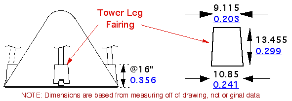
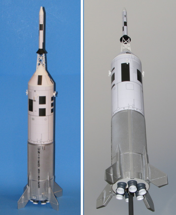
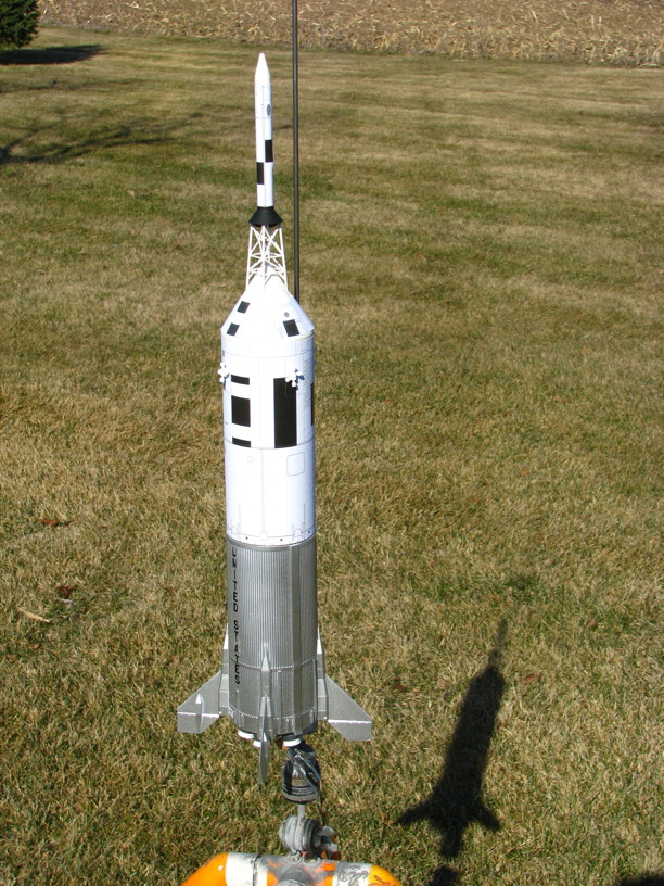
Building the Estes Little Joe II: Tips, Tricks, and Modifications

The Rocketry Forum

Help Support The Rocketry Forum:

This site may earn a commission from merchant affiliate links, including eBay, Amazon, and others.
George

The only info I need is for the little rectangular housings which the legs of the tower go into.
I really only need a station height for them..and how wide the would be...you have a station height of 258.5 for the lower edge of the tip cover..but nothing for the housings.
I can always just scale off your drawing if the info is not at hand..

I draw everything full size and scale down and will then scale a little more to account for .010 sheet..
I can derive everything else from your drawings on your site.

What I want to make is a master that looks just like your cast part in the photo.
I will then just do strip polystyrene to build out the rest of the BPC on the capsule.

Thanks for helping with this info...

Dan
 
George

The only info I need is for the little rectangular housings which the legs of the tower go into.
I really only need a station height for them..and how wide the would be...you have a station height of 258.5 for the lower edge of the tip cover..but nothing for the housings.
I can always just scale off your drawing if the info is not at hand..

I do not recall just where I got the dimensions from, or even if they may have been scaled off from a drawing. Possibly notes from Tom Beach, possibly the "NARTS" Saturn drawings. This was over 25 years ago... :)

I opened up one of the old Little Joe drawings and measured, and got the dimensions below:

laoYmoQ.gif


The resulting scaled-up full size dimensions therefore are a bit fuzzy, good enough for making a scale part, not legit for the sake of true data. I have converted them to 1/45 scale, in blue text.

So, when I made the 1/39.5 scale models, 1/4" square Plastruct worked out fine. Of course I didn't go for the exact scale shape with the slightly sloped sides, narrower at the top than the bottom, I just left them parallel. OK, so that was another nod towards "sport" scale vs precision scale, that bird had plenty enough other bits and pieces to build right.

UPDATE - Well.... 25+ years or not.... upon further review, I think this is it. The fairings might have come from an Apollo BPC-LES drawing that was used as "cover art" on the 1988 NAR "Pink Book (contest rule book). Tom Beach & I could never find the original source for the drawing used on the cover, but it was more accurate than some earlier NASA drawings were. The famous NARTS Saturn drawings did not even show BPC's, and had other errors due to being drawn before the designs were frozen). On thing that is "off" is the BPC detail shows a Block-II type BPC, the Umbilical detail was different than used for Block I and the splice seam was shifted, plus LOTS of other BPC details on the hatch & Window side that were not on any of the Joe BPC's. But the tower leg fairings looked like ones seen in photos.

So, here is a link for the Pink Book front and back cover pages, side by side (the scan of the book missed a bit).

https://imgur.com/Lvi6hgD

And below, here is the relevant part of the BPC:

S5kiqii.jpg


- George Gassaway
 
Last edited:
George

Thanks...that should do it..

Also, a BIG thanks for all the great posts in this thread...guess I have a lot of work ahead of me..:)

Dan
 
I switched to Plastistruct Plastic Weld and I haven't been able to pull any of the pieces off (even when I made a mistake). Just be sure to clean off the old cement first.

Brandon
 
Going to be immodest...

I did the design/layout/pre-press on the Pink Book (as in really, really pink...the printer misinterpreted my handwritten 30% Red color instructions and did them at 50%) that year. The BPC drawings are mine but would be for a Block II spacecraft BPC (as George points out).

I got to work very hands on with the LES and BPC for Block II a few years back...some stuff "might" apply to the Block I items that flew on LJII but I'd rather leave accepted history alone for now and not muddy things with what might be applicable to Block I vs Block II by trying to be "specific" in pulling numbers from my aging brain. I do know know that the attachment/alignment devices (not simple bolts) that attached the LES skirt to the tower was the same between the two but not the attachments at the base of the LES tower to the spacecraft. All of the LES tower legs and cross members were larger in diameter than for Block I (Block II had thicker more strategically placed ablative on them). The LES motor nozzles were different (they had a higher expansion ratio) and the skirt was slightly larger with beefier internal structure for Block II (at least what I measured on Block II was larger vs. circa '65-66 drawings, which are almost all Block I).

I had worked quite extensively with Mike Dorffler on developing LES motor and skirt Block II drawings to the point of making bolt-rivet-screw level 3D models (drawing models) and was getting ready to start trading efforts with him on the tower but, unfortunately, he passed away before we got to the tower. Mike was amazing on matters of detail.

Maybe if I keep paying attention to various forum posts my "enthusiasm" for getting back to scale modeling and scale drawings will "come back" and I will create shareable drawings and data.

John Pursley
 
Going to be immodest...

v6OdFpj.jpg
Go4ZTMP.jpg


YOU also got to play around with 1:1 scale rockets (Saturn-V restorations/preservations)....and paid to do so :)

Wow, I had no idea you were the source of that BPC/LES drawing on the 1988 Pink Book cover. Makes sense, now.

I know what you mean about scale modeling burnout and such. Part of why these Little Joe kits are so neat to build now. No scratchbuilding except for personal choice like the Recruit nozzles (relatively easy since I wasn't trying to get them accurate, just representative). And as sport flight models rather than contest models, no pressure to try to be "perfect" (never achievable anyway). Also opening the door to just do wraps rather than decals or other stuff, including representing the BPC splices and such. And the various "Oops" errors (and crappy paint) along the way wasn't an "OMG MUST REDO IT" catastrophe (close-up in person, the aluminum paint I used really sucked, and would have been a massive if not impossible task to remove 100% to repaint it). No catastrophe until the actual catastrophe (crash) anyway. But that crash didn't ruin my day. If Karma said of the important models I build and fly this year, that is the one that had to crash, I'd gladly take that deal.

- George Gassaway
 
Last edited:
I get upset when I see other folks crash their models but for some reason, I don't get all that freaked out when MY models crash. I guess I could be called the "Saturn V Crasher" because I crashed my Internats Saturn in '83 and scattered my Saturn across the desert at the Tuscon NARAM (96...97?). Since the last Saturn crash I boilerplate EVERYTHING important. AND I am notoriously slow in building each project. I think every NARAM Scale model I have done has taken at least two years (well, the smallish 1/24 Mercury Redstone came together in about 9 months).

The Little Joes are quick and fun builds. I fretted a bit over the "under engineered" fin-to-body fin attachment mainly because I didn't want my customers that I am doing builds for to announce "John Pursley built this model" after they sheared their fins off just prepping it or on recovery. My first couple of "sparred fin" Little Joes used a 1/4" dowel as in my posting earlier this week though I have switched to 1/4 square hardwood spars. It's just easier and faster to cut a neat square hole than to drill/cut and clean up a round hole (at least for me...plus I am the laziest person on the planet when it comes to building models).

The nice thing about the skins is that they can go over a pre-finished model that was either buggered up during construction or to freshen up appearances after many flights.

I am starting to feed my "next revision" LJII (and MR, too) skins into my sales stream. Fixed a few detail errors and improved some others.Perhaps the more "significant" change is that I have introduced a very subtle "two tone white" to the SM wrap. Not scale and not "accurate" but kinda looks "more real" especially when you notice the non-uniform white of the SM on A-004 photos.

Oh, one other thing I am doing that may be handy for modelers. I am bending the forward tang of the engine hook outward and epoxying over it (to keep the hook from moving fore and aft) as well as leaving the engine block out so modelers can use any length of 24mm motor and still have an engine hook to prevent ejection. It's something I have done for quite a few builds over the past couple of years.

Finally, I located the LES/BPC drawings Mike Dorffler and I were working on a few years ago. Just looking at them is giving me inspiration to try to finish them sometime in the near future. Heck, just participating on this forum is giving me inspiration.

John Pursley
 
Last edited:
While building my LJII kit a couple of months ago, it struck me that one of the weak points of the model was the quality of the molding on the RCS thruster parts. (This shouldn't be construed as a complaint, just a recognition of the limitations of plastic molding technology 45+ years ago when the tools were cut.) In particular, the wall thickness of the RCS engine bells is waaaayy too thick, giving them a particularly non-scale appearance.

A potential replacement for these parts might be found in one of the special detail part packs being offered for the new 1/48 scale Space:1999 Eagle Transporter kit. While that new kit comes with plastic molded RCS thruster parts, the manufacturer also offers a separate set of turned aluminum parts to replace the plastic parts supplied with the kit. I was able to eyeball these parts through their plastic packaging at the hobby shop the other day, and they appear to be just about the same size as the RCS parts in the new Estes LJII kit. If you're interested in super-detailing your Little Joe II model these might be worth a look. If you work in a hobby shop, do us all a favor a see how these detail parts compare size-wise to the thruster nozzle parts from the Estes LJII kit.

https://www.culttvmanshop.com/Space...ch-kit-148-scale-from-Round-2MPC-_p_3437.html

https://www.cybermodeler.com/hobby/details/mpc/detail_mpc_mka016.shtml

https://www.hobbylinc.com/htm/pll/pllmka16.htm

Hope this helps,
James
 
Houston.... we have an UPDATE!


[video=youtube;hkytvDGwNqU]https://www.youtube.com/watch?v=hkytvDGwNqU[/video]
 
Last edited:
After the crash of my Little Joe-II due to the lugs popping off, I considered several things to do with it. The Apollo parts were smashed, but the Little Joe part was rebuildable. Biggest issue was the fin that came off, taking some of the corrugated wrap with it.

H35tcw9.jpg


A portion of the wrap was lost, which would leave a smooth irregular gap.

What to do? Well, I chose as my “Prime Directive” for this to be fun, and to do a quick rebuild at the cost of making it look great. It already had some issues before the crash, silver paint that was a mistake.

So, I did not cut into the body wrap of another kit to get a splice to replace the ripped portion. I did the repairs and glued it back together quickly. This time, the lugs were glued on with Plastruct Plasti-Weld.

N67cQnB.jpg


The fin reattachment was an opportunity to use a method I’d speculated before, which John Pursley also used for his model, a spar glued into the fin, attached to a hole in the body tube. For this model, I used some 3 x 3 mm square (about 1/8”) graphite tubing. A solid graphite rod of 3/32” to 1/8 would also have been good, and probably a 1/8” dowel would be fine too, I went with the 3x3mm graphite since I had it. Glued that into the fin at 90 degrees. Drilled a hole into the body tube, at the correct position. Actually the hole was a bit off so I had to widen it a bit in one direction but that was OK. I used Plasti-Zap to glue the fin back onto the body. After curing enough, then I used thick CA inside the body tube to secure the graphite spar inside of the tube. I will use that method to build future models, it's easy enough to do and well worth the increase in strength to withstand hard landings.

C0SARMS.jpg


One “plus” of the crash was that the centering rings had come loose, the rear ring completely. So, I re-glued the forward ring securely, but left the rear ring unglued so I could remove it as desired. Being able to have that ring come off made it easier to apply the thick CA to secure that fin, and would also allow me to remove it to do the same repair work with other fins if they broke off.

DqTIBPu.jpg


The model's Apollo parts from the Service Module on up, nothing could be salvaged other than the 4 RCS quads. So, this is not a 100% rebuild, if I wanted to have Apollo parts, I needed to make use of parts from a 2nd kit.

Actually I did seriously consider converting it into a proposed orbital payload launch version, using a Minuteman Missile for upper stages. That would not have required any parts from a 2nd kit, but would have required coming up with some custom adapters.

Oh7zXVd.jpg


But I went a different way. Rather than rebuild it as A-004, I rebuilt it as something else…..

Little Joe-II Mission A-005.
 
Last edited:
6I8pTYd.gif


Oh, you never heard of Mission A-005? There was a proposal to launch a mission with a Live Service Module, presumably to test out an abort using the Service Module. On a Saturn flight, that is how an abort would have been done after LES sep, if the Saturn had developed a problem. The engine(s) would be shut down, and 3 seconds later explosive bolts would fire to allow the CSM to separate, first using RCS thrusters to pull away, then use the SM’s SPS engine. By that phase of flight the atmosphere would be so thin that it would not matter if the rocket had gone out of control and was tumbling or whatever, there simply was no immediate danger requiring rapid acceleration away from it by the time that the LES was jettisoned.

Now, for a Little Joe to launch a live SM, it would have needed a long adapter to allow for the length of the SM engine nozzle. The Block-II Saturn-I’s that flew Apollo boilerplates had a cylindrical adapter . But those never flew with a live SM. Given the large diameter of the SM nozzle, it would seem to be risky to expect a perfectly straight pull by RCS thrusters. The official Apollo abort mode procedures called for the adapter itself to separate its 4 panels, as the Saturn-IB and Saturn-V S-IVB stages did with the 4-segment panels. So, after some research, finding no proof either way of what NASA would have done with a live SM separation on the Block-II Saturn-I’s, or Little Joe, I decided to go with a 4-panel design. Which means that I modified the SM wrap to not only be 3.2” taller, but to have some details drawn in that could be plausible representations of a 4-panel adapter on such a Little Joe-II mission.

uA0PEU2.jpg


So, the old 3.4” tube for the SM was removed, and a new longer piece was added.

ZIrg6KI.jpg


The paper wrap went on well. Also, the rest of the Apollo parts such as the LES and cone were quickly built, painted, and had wraps applied to them. The RCS quads from the original model were salvaged and re-used.


oIPRjJO.jpg


pUz2q3j.jpg
 
And finally, it was ready for a club launch held last weekend. For another flight on an E15-4.

8t5mh8H.jpg


Here is a great liftoff shot by Carol Marple.

u3JhD6d.jpg


And a nice at-pad-looking-up camera view:

OYkqpzf.jpg


Also, this view from a GoPro camera:

NOVFalw.jpg


So, it took off straight, but weathercocked a good bit after leaving the rod. Nothing as severe as the first fight that snapped the lugs off at liftoff, but pretty bad weathercocking. It got to a good altitude, but started coming down down, down, faster and faster. Was looking like a “higher” repeat of the first flight, like it was going to crash again. But then at about 50 feet off the ground, it ejected. Here’s a youtube video with both the GoPro footage and a very slow-motion ignition sequence from the at-pad camera.

[video=youtube;zHNBSVVFBNk]https://www.youtube.com/watch?v=zHNBSVVFBNk[/video]

The main chute never had a chance, it was packed on purpose to deploy slowly. The 18” plastic drogue, some of the over-the-top lines ripped thru. But, the chute did slow it down a good bit. It had a “hard landing”, tail-first, which broke off one fin, and all but one of the friction fitted Algol nozzles popped off (no big deal for them). All things considered, a fortunate result.

qQUIBKV.jpg

(stick was laid over 18” red drogue chute to keep the wind from opening and dragging).

Now, the biggest issue was that the time delay was way too long. Ejection was about 8.5 seconds after burnout, for what was supposed to be a 4 second delay. The motor did chuff, two short chuffs before finally igniting, so that seemed to be an issue (I had the ignitor all the way up). Very strange though, I have flown dozens of E15-4's in the past 25 years or more and never had that happen till now.

RynQDKy.jpg


The broken off fin…. this was a fin that had cracked part of the wrap in the first crash. I had used Zap Plasti-Zap to seep under the wrap and bond it better to the body tube. And that helped a lot, as the fin did not rip the outer corrugated body wrap past the fin root. Instead, it mostly ripped out the alignment and glue tabs. So for repairing, I did exactly the same as for the other fin reattachment, 3mm square spar glued into fin, hole drilled thru the body, and so forth.

And so it was ready for another day.....
 
The next day…… a beautifully sunny blue sky day. And not too windy, about 5 mph. I decided to go with a D12-3, those do not “Chuff” and D12-3 delays are pretty reliable. Flew at a local site, by myself. Set up a couple of fixed cameras plus using a handheld while launching.

vUomSYL.jpg


Lv5CZfw.jpg


And, launch!

3374O5f.jpg


UeGTj8j.jpg


Very nice boost, only very slight tip-off. Ejection very close to apogee. Chute out! Well, 18” drogue chute out. Main 36” flare chute didn’t get out.

Gq7m9r9.jpg


Still, it landed safely with the 18". But not quite the flight I wanted. So, I reprepped to fly again, and having seen that the 18” chute brought it down safely, decided to change the 36” chute to the kit’s 24” chute. Also, since the GoPro set to wide angle had a nearly 90 degree field of view, I angled the rod to adjust the flight path a little bit in hopes of getting the whole flight on the GoPro.

And so….

wLVoWho.jpg


MlqrJQD.jpg


d2MIauV.jpg


lPDaHDC.jpg


So, finally got in some nice flights. Flies nice with D12-3 power, though of course those were not high-wind launches. Plenty high enough altitude.

The usefulness of multiple chutes was proven on this model. Had it used separate chutes, with the "Capsule" and LES coming down separately, then the main body would have crashed twice with no chute at all.

It may be a few weeks before I fly it again. But when I do, I'll try to get better images of the recovery system. Also, I need to rearrange the shock cord attachment points to get better horizontal separation between the main and "drogue" chutes, so the model will not sway as seen in the final image.

I'm very glad to have rebuilt it and to have found this one flies on a D12-3 about like I recall my old Centuri model did on a D12-3.

I also want to note that Estes Customer Service sent me a replacement kit. Much appreciated.

- George Gassaway
 
Last edited:
Nice video George, and I love that old music. Reminds me of the documentaries we used to see in school. I must say, the rocket sure did get damaged into lots of pieces. Did it end up hitting the curb?
 
Nice video George, and I love that old music. Reminds me of the documentaries we used to see in school. I must say, the rocket sure did get damaged into lots of pieces. Did it end up hitting the curb?

Uh, I think you missed or forgot about the crash a month ago. When the lugs popped off at launch and the model pitched severely, crashing nose-first at VERY high speed. Yes it crashed into a curb, but that was merely insult to injury, crashing into dirt would have produced much of the same result.

https://www.rocketryforum.com/showt...ricks-and-Modifications&p=1556379#post1556379

All of the music is from the Six Million Dollar Man, in one way or another (yes, even the bit at the end).
 
I remembered that post, just not how many pieces it broke into. Six Million Dollar Man- those were the days!
 
I don't recall seeing this on the forums...I'm sure in this " Internet Age" it's probably in a million places. I was just digging through my files to find information for someone else and...

It's the A-003 being hoisted. There's a pretty good view of the white "insulation" on the aft bulkhead (no, it's not some kind of cover) You can quite nicely see some of the the lug-spars that the fins attach to and as well as the pads on which it sits on the launcher. It's interesting to compare the "bare" bulkhead with an insulated one.

S-65-13573.jpg
A-003 S-65-13573

s-64-17762.jpg
A001 S-64-17762


John Pursley
 
Fins:

I have updated my "fin spars" from 1/4" dowel to 1/4" SQUARE hardwood. The main reason is the added circumference area that becomes available for gluing where the spar passes through the walls of the body tube (plus it's easier to hand-sand [though I have progressed beyond that] the tapers where the spar goes into the fin and it also gives a larger bonding area inside the fin). They also distribute any landing loads through both the engine mount and a significant portion of the body tube. If you manage to tear a fin off with this arrangement then you have had a REALLY serious recovery problem.

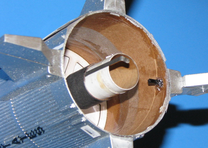
Additionally, having heard some reports of "sooting", launch blast back, and heat damage to the plastic nozzles, I figured it is an easy matter to make the whole rear bulkhead with the scale nozzle removable. The fin spars center and support the rear of the engine tube so the bulkhead is no longer needed for that. I use the bulkhead during construction to make sure the spars exactly center the engine tube. Other than that, the bulkhead becomes an "unattached" part of the model for display. Just paint one side of the bulkhead white, paint and glue the scale nozzles on the painted side of the bulkhead, test fit and sand for a snug but removable fit and, voila! You have a nice "display" nozzle assembly that won't get trashed in flight...and you save a half-ounce from the rear of the model for flight.
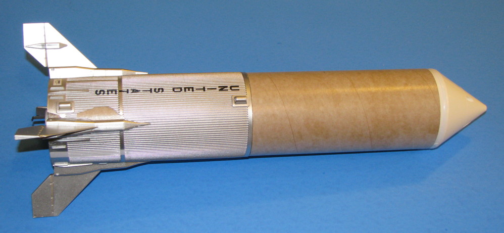
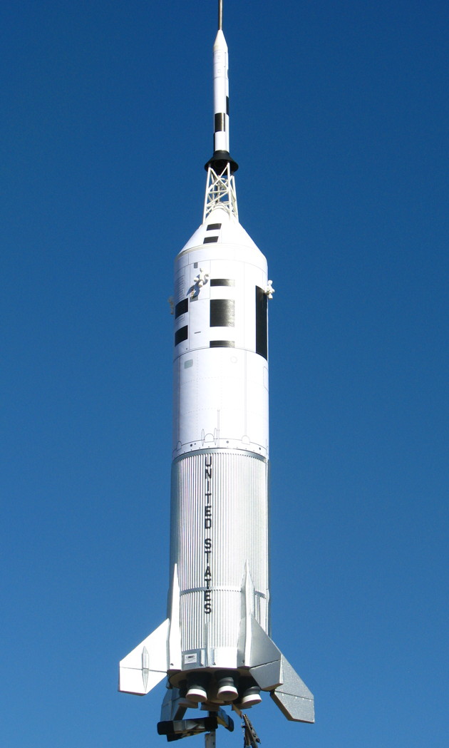
WP_20160327_12_38_10_Pro[1].jpg

Those Decals:

I've heard several modelers fretting over having to get the kit "UNITED STATES" decals to nestle down in the corrugations (most hadn't even tried it yet). During application (there's another tip following that you do before applying the decal) just soak the decal on its backing (which should be cut as close to the lettering as you can) in REALLY WARM water to make the decal soft and pliable. After about 15 seconds it "releases" from the backing. Position over the raised centerline of the stringer over which it is to apply and slide the whole decal along the long dimension so that about 1/4" of the "S" in "STATES" is positioned just ahead of the longeron. the bottom of the last "T" in "STATES" positions toward the aft edge of the splice ring. Now, holding the "S" in place with your finger, grasp the other end of the backing and in a straight motion, keeping all the letters centered over the centerline corrugation, slide the backing forward and out from under the decal. Using a very soft artists brush (I use a #00) and liberal amounts of VERY WARM water, "dab" the decal so that it nestles (or begins to) into the recessed corrugations. It goes a lot faster and easier than you think. The decal is fairly tough so you pretty much have to TRY to damage it.

While the decal is still wet, liberally apply a decal setting solution and DON'T DAB during or after applying the stuff. I use Walthers Solvaset. It's very strong and as it evaporates it really softens the decals and "sucks" them down into the corrugations. It will completely evaporate and do its job in a few minutes. If on close inspection you feel it still hasn't pulled the decal down as you like, liberally apply more setting solution. BTW, support the model horizontally and do one side at a time, allowing full drying before attacking the other side.

The "Other Thing" Concerning Decals:

What ever clear you plan to use on the model as the first clear coat you apply OVER the decal, apply a coat of that same clear to the model BEFORE you apply the decals...especially over metallic paints. If you don't, the metallic paint will react a bit differently to the decal than to clear paint and you end up with a visible outline around the decals (but, it's not so serious with the Little Joe because the corrugations "camouflage" the outlines of the decal. Once the decals has dried, use the same clear over them as you used under them. Been doing this for almost 50 years and it's a rule I never break.

But WHAT Clear To Use?


I've played with several different "silver" and "aluminum" paints over the years and found there's nothing easier, better, and more "aluminum looking" than Testors Spray "Metallic Silver"...if you use it with the right clear coating. What do I use? I use Pledge Floor Care (it's the same as "Future Floor Polish" from a few years back...that EVERY plastic modeler knows about). When Pledge is applied over the Tesors "Metallic Silver" something almost magical happens right before your eyes. The sparkly "Metallic Silver" instantly takes on the appearance of honest to goodness ALUMINUM...and even if the bare "Metallic Silver" looks a bit un-uniform, once the Pledge hits it things are just perfect.

Most model rocketeers don't have airbrushes or airbrush skills, so...Don't laugh at this next tip...and it works exceeding well with the Little Joe because of the corrugations. I apply the Pledge straight out of the bottle (I just squirt a bit in the center of a saucer) and use a high quality 1" FOAM artists brush to apply. YUP. No airbrush. Apply in single, non-stop, linear, barely overlapping strokes starting at one end and stroking all the way to the other end on each pass. Don "brush over" previous passes. Don't use "back and forth" strokes. Just go all the way around the model (fins too) using this method, then let dry for about 15 minutes. Then go back and apply a second coat. Though the Pledge will deliver a very high gloss, when it goes over the Testors Metallic Silver it really doesn't look gloss (the way scale modelers like it).

WP_20160405_21_39_52_Pro.jpg

After many frustrating experiments with applying clear over metallics over many years using various spray lacquer/enamel clears...Krylon, Rustoleum, store brands, others...I have found that they all can deliver "surprises" when sprayed over a metallic paint ranging from outright "attacking" it, to "fisheyes", uneven finishes. Never had the problem with Future/Pledge. The other nice thing about Future/Pledge as a clear coat is that it acts as a primer and a barrier between the metallic surface and other "spray clears" if you want to apply coat of matte or flat clear like Krylon and others, knowing that your metallic finish is safe and sound under the Future/Pledge (which BTW is a water-based air-cure acrylic). I've NEVER had it attack finishes over which it is applied...even other water-based acrylics or the older water-based polyurethanes. Also have never had it have any problems with "sticking" to other paints.

Escape Tower:

One last thing just occurred to me after communicating with a modeler a few minutes ago who was having problems assembling the escape tower. I assemble mine by installing the two legless sides of the kit parts to one legged side resting face up on a flat surface. I'm now using MicroMark "Same Stuff" (presumably same as Tenax) and it forms a very strong and almost instant bond. Anyway, the resulting "U shaped" structure misleadingly welcomes the quick installation of the ring that is "trapped" between the three side. Yeah, Right. Just TRY to "easily" position that ring so that the four little nibs line up...and just TRY to keep it in place while you glue it. Well, there's a simple solution. Just sand the nibs off the ring so that you have a nice, projection-free ring. It litterally just drops and STAYS in the proper place while you glue it.

WP_20160330_11_41_16_Pro.jpg WP_20160330_11_48_58_Pro.jpg

That's it for now.

John Pursley
 
IMG_1252.jpgIMG_1249.jpgIMG_1187.jpgIMG_1224.jpgIMG_1252.jpgIMG_1181.jpg


[video=youtube;naybBcaGoyk]https://www.youtube.com/watch?v=naybBcaGoyk[/video]


I just wanted to say thanks to you guys for posting some really valuable building techniques. I'm really enjoying flying this kit!

I've flown it twice with George's drogue, and main chute arrangement. Second time the drogue was the one that didn't work, but the model came down nice on an Estes 30" pro series chute. Both E30-4T.
 
Last edited:
This is a great thread and, after a couple month hiatus, I've finally had a chance to dive into my Little Joe II. I do have a couple of questions before going much further, though.

First, it appears by the kit instructions along with looking at some actual builds here, that the tall longerons (parts N) straddle the long tunnel (part M), whereas George's drawing of the main body back on page 1 of this thread shows the short longerons (Parts O) straddling it instead (assuming I'm looking at the drawing correctly). I'm guessing the former is correct (tall ones)?

Another thing is that I'm considering building mine as A-003, simply because it had installed the six Algol sustainer motors that the kit includes. From what I can tell, the roll pattern on it and most major observable details are the same on it as on A-004. Am I correct in this, or are there major details I need to change from what's included in the kit?

Lastly (for now!), has anyone used or considered 5-minute epoxy or the like to mount the fins and launch lugs to the main body? I tried to review everything in this post and didn't see any mention of it, but could have easily overlooked it. There is obviously an issue with the corrugations on the wrap leaving less contact area for the fins especially, which I can see as one reason for the parts failing, and I wonder if epoxy might have more "bite" than glues. But I like John's method with the wood dowels for insurance!

TIA,

Mark
 
Mark,

I was hoping that no one would notice but I DID misposition the "long" longerons on one of my builds (was able to go back and carefully slice off the offending parts and correctly reposition)...and, of course, that's the one that appeared in my photos. The actual Little Joe II sat on the launcher and was tilted so that the long electrical cover was nearest the launch pad tower...the "high side." This meant that most of the weight of the LJ rested on the "low side". Hence, the "long" longerons are on the low side (short tunnel) to better distribute the stresses along a longer portion of the corrugated skin.

Epoxy just doesn't bond to plastic or work in a way a good "cement" works...even if you "rough up" the surfaces. You are right about the contact area, though. However, the real "fin shear" failure begins as the bond between the corrugated skin and the body tube in the fin areas fail and as the fin rotates away, pulling the skin with it, the skin eventually tears. It really doesn't matter how strong the adhesive between the fin and the skin is (provided you use the right adhesive), you still run a high chance of ripping the skin off the body tube. For my very first Estes LJ build I used a "Goop" type of adhesive (think, Shoe Goo, Zap Goo, etc.) specifically between the skin and the body tube at the fin areas as well as liberal amounts of the stuff when gluing the fins to outside of the skin. It was strong...and absorbs shock better than a rigid glue, but just by grabbing a fin and twisting at it I could still see I would be in for trouble on rough recoveries.

But, after seeing post recovery damage it was very easy to ascertain what the real culprit was so I came up with the "rather massive" (as one fellow said in a private communication) fin spar solution. I was blown away by George's carbon tube through the body tube wall as I was eyeing some carbon kite spars in my bin. But I decided it would be easier for me (I am lazy) to go with a larger wood spar that would have a large bearing area inside the fin (I didn't want to mess with figuring out how to secure a skinny rod/tube in the fin when with a little sanding I could just "jam" a larger wooden part in there...George has more "finesse" than me). I also had in mind to make the aft bulkhead with the scale nozzles removable and (again, I'm lazy) didn't cherish cutting a ring to replace the kit's rings that were now part of a "display" part. The easy thing to do was to simply extend the fin spars all the way to the engine tube. Voila! I now had a super-strong engine mount AND a super-strong fin mount. I've been weighing the additional weight of my spar system and it adds 9-10 grams to the model BUT, removing the scale nozzles and aft bulkhead for flight removes about 14 grams.

John Pursley
 
Last edited:
Hi John,

Thanks for the clarification. I use epoxy on certain parts of resin builds I do; it provides a nice, strong bond when I need it hence my consideration of using it for the fins/launch lugs. I usually use Tamiya extra-thin cement for my plastic model builds so might try that instead (no Plastruct Plastic Weld on hand).

I can only assume that Estes built and flew a number of these kits in the design process, so wonder how they (presumably) avoided the issues being discussed in this thread. This is not so much a complaint but an observation; I really am excited about this kit and hope Estes continues this trend of releasing "oldies but goodies." Now if only the classic Gemini-Titan is next!

Mark
 
It's easy to metaphorically compare apples to oranges when talking adhesives. Resin models and styrene (of whatever flavor) are significantly different materials. Epoxy effectively bonds styrene by (very general term coming up...) "sticking" to the surface without strongly chemically interacting with the styrene whereas epoxy has chemical similarities to "resin" models that allows it to form a different (and stronger) bond than with styrenes and acrylics. Liquid cements, on the other hand, actually dissolve the surfaces of the two plastic parts and fuse them together...kind of "melting" them together so that, if properly done, they become one part. Generally don't use plastic liquid cements for resin models and don't use epoxy for plastic models.

I don't know about the formulation of Tamiya extra-thin. Since the skin of the Little Joe II is ABS plastic, not just any liquid cement for plastic will effectively dissolve it for good bonding. The liquid cements that will effectively cement ABS to what we would call good old styrene (the Little Joe fins) need to contain either methylene chloride or methyl ethyl ketone (MEK) as the predominant ingredient. Even liquid cements like Testors liquid cement contain MEK but evidently not in as high a proportion as other liquid cements intended for ABS and acrylics like Lucite and Plexiglas (Tenax, Plastic Weld, Same Stuff, Plast-I-Weld). I've begun using "Same Stuff" from Micro-Mark and the stuff fuses parts together in about 10 seconds and the joint is about as strong as it will get in an hour (it's primary ingredient is methylene chloride as is that in Tenax).

I, too, would have assumed rigorous testing before unleashing the kit to market, then again...

John Pursley
 
When it comes to gluing anything to the vac-formed body wrap, whose chemical composition has not been nailed down (was once thought to be ABS but a solvent glue that works with ABS did not do a thing to it), I only trust two glues which I have used and (now) know to work.

One is Plasti-Zap, by Zap, which is a medium viscosity Cyanoacrylate glue meant to use with plastics.

The other is Plastruct's Plasti-Weld, orange bottle. It is a watery type of solvent based glue, which melts the plastic and fuses the parts together.

For my model's rebuild, I used Plasti-Zap for attaching the fins.

For the lugs, longerons, and mini-longerons, I used Plasti-Weld.

For reattaching broken-off fins, I used a spar glued into the fin, and hole drilled into the body. Plasti-Zap was used for surface-gluing the fin back on, then after it set up I used thick CA inside the body tube to anchor the spar. For future models, I'll use spars in the fins to begin with, and cut holes into the body It's a pretty easy way to do it, since the hole does not have to look pretty since the fin root fairing covers it over.
 
I built my first Estes Little Joe II before being pointed to this thread. James' introductory note pegging it as ABS more or less "indicated" that it wasn't your common "polystyrene." I had kind of figured it was either a butyl plastic (butyrate) or its cousin ABS...or something very similar. I've called it ABS here since seeing James' posting.

My first bonding shot at the stuff was with Testors Liquid which was a no go. Though it contains MEK...known to bond ABS...I just figured it was in not enough proportion in the cement to bond the Estes skin so I switched to "Same Stuff" (a Tenax equivalent...hence, the name) and it worked just fine. Same Stuff is based on methylene chloride which bonds ABS...but it also bonds Butyrate (which MEK is not so good at) which is another material commonly used in vacuforming. But, I never thought about the Estes skin as being possibly other than ABS until George's last posting. Methylene cloride is almost a "universal" plastics solvent and will also bond Plexiglas, Lucite and just about any acrylic. I truly don't know whether the Estes skin is ABS or butyrate or whatever...I just know the methylene chloride cements I have used on it do a very good job at truly fusing it to the "polystyrene" injection molded parts in the kit.

I'm a closet CA freak...and I use it in some very strange ways (but typically not for applications such as present with the Estes Little Joe plastic parts...though I do use it to glue my wood spars to the inside of the Estes fins [I use both thin and thick CA there]). Then again, every modeler with a fair amount of experience will come up with ways that "work for me but not for anyone else."

Regardless. I just LOVE the Estes vac skin because it's robust, uniform, and just plain good looking when compared to many other plastic wraps including those in the Estes Saturns and others. Once the "right" cement is nailed, it's as close to "ideal" as I can think of any recent model.

Now, the whole matter of how the fins mount is an entirely different issue...not the fault of the skin in the kit!

John Pursley
 
Here's the lugs of my Little Joe-II, glued to the wrap using "Bondene", listed as specificaly bonding Styrene and ABS:

AoBF2U6.jpg


Ok, so those lugs are not on the model, which crashed minutes before. The lugs were left on the launch rod, because they snapped off at launch.

I later did a test where I applied Bondene to the inside of a spare wrap. The Bondene did NOTHING to it. I might as well have applied water to the wrap, the Bondene was that chemically inert (In case there was some crazy mold release issue, I scraped the test surface to remove any possible mold release - still nothing). So that is why I suspect that the wrap is not ABS after all, but something else (PVC? Butyrate? Dunno). The only other logical explanation, if the wrap were ABS after all, would be that the Bondene is total garbage that does not work with ABS despite the label's claim that it does.

In any case, the kit's wrap definitely is of great quality and crispness. Wish I knew what it was, for two reasons. One, for future knowledge of what glues to get to test on it. The other, for future projects involving vac-forming, especially for any possible wraps (Like an ET intertank). Might make for good contest nose cones too, depending on the mass/strength tradeoffs).

I just now recalled when I did vac-form some thin Butyrate sheet for 40mm FAI nose cones. They formed nicely, but the thinnest sheet i tried, while producing a 40mm nose that was lighter than styrene, was too wimpy for flight loads. And the next size up was plenty strong, but the 40mm nose was heavier than styrene, so I stuck with styrene. Those vac-formed butyrate noses were very shiny, and these Joe kit wraps are very shiny. That does not mean the Joe wraps are actually butyrate, as cosmetic surface appearance means nothing as regards to chemical properties and solvents for glues. But it is an interesting data point. I do not have any Butyrate on hand to try any tests with.

- George Gassaway
 
Wow...almost look looks like tube type cement (likely optical "conclusion" on my part <G>). I kind of have to chuckle at the appearance of them remaining on the launcher though the results certainly aren't a laughing matter!

I presume you are talking about Plastruct Bondene (while label bottle). That it (Bondene specifically) doesn't work is good to know. Thanks for being specific about what it is. I've only used Plastruct Plastic Weld (orange label bottle) and not the Bondene on the Little Joe. Just checked at Plastruct website and you're right, they say "Bondene" works with ABS. I do absolutely know the Plastic Weld works (just tried it to be sure...darnit George...you've made me go and open another LJII kit! Like I said before, I'm an experimentalist and just cant resist.). I've used Plastic Weld almost exclusively since about '69 or '70 until recently (past couple of years) trying Tenax and others I mention here. AND I just tried the Plast-I-Weld from Flex-i-File (just opened a fresh bottle) and it works. I've used "Same Stuff" from Micro-Mark on the last four Little Joes so I know it works. Don't have any more Tenax...but "Same Stuff" is supposed to be the same stuff...take that for what it's worth. Tube type Testors doesn't do a thing. Liquid Testors seems to "dull" the surface of the skin a bit but doesn't seem to actually dissolve it and fuse with styrene snippets...so cross it off the list, too.

I still pretty much think the wraps are ABS (my only evidence is from how it behaves from my past experience with ABS and the "ABS" cements above working on it) and that, in this case the "Bondene" is likely suspect. Like you, I see the same "shininess" of the Estes plastic wrap as being "possibly" indicative of either ABS or Butyrate...but not definitive. There are plenty of other plastics it "could" be. Styrene almost always looks a little less shiny when vacuformed. Regardless, now that I have found cements that most definitely fuse (and not just "stick") the plastics in the Estes kit I don't care what the plastics are...I'm going to stick with the cements that work by crackie!

One more thing. I recall in communications (or reading about it...May have even been Fine Scale Modeler...) years ago that liquid cements can "decompose" and lose their effectiveness. I don't what what SPECIFIC cements I am vaguely recalling. I do recall it being said that when they start smelling like "sweet vinegar" to toss them out.

Now that I've mentioned Fine Scale Modeler...hey all you rocketeers out there...it's one fine source of modeling information exactly like that being discussed here that makes it a worthwhile publication to subscribe to even if it's NOT a rocketry publication.

My "quickie" tests above were performed on the backside of a LJII wrap (very rear edge of the fin area) with pieces snipped from the plastic sprue in the kit to be absolutely sure the cements I cited actually work with the plastics in the Estes kit.

A little off topic but you mentioned PlastiZap previously... Tip: it doesn't "boil" to the degree that the non-plastic formulations do when it cures in heavy applications...you can actually make very nice uniform small fillets with the stuff that don't end up looking "lumpy" after it cures/dries. Don't ask what model rockets I use it in this role for...

What next... Oh,I need to go out and crash a Little Joe so I have an excuse to build an A-005 "alternate universe" stretch limo version. <G>

John Pursley
 
Before I start on the intended topic...

George Gassaway, in his last post to this thread, made one of the most valuable comments I can think of when it comes to gluing "anything to anything else" (my words): "I only trust two glues which I have used and (now) know to work"

I trust a few more than two glues but the important point he made and should be a Golden Rule when building any model...Trust ONLY the adhesives you KNOW to work.

Now, for an "other" way to attach Vac Wraps.

For about 20 years or so I have used what is called "transfer tape" in building some of my scale models. I first used it on my big Vanguards and Mercury Redstones (see my web site at https://www.accur8.com) to adhere embossed (mostly rivets and small raised or depressed details) .005" thick styrene sheet to the bodies of those rockets. At the time I used a "generic" transfer tape I found at an art supply store. I have since refined my choices of transfer tape to mostly 3M 966 or 3M 924 transfer tape (the 3M 924 is available from Micro-Mark). I currently use this method to attach wraps to models such as the Apogee and Estes Saturns.

Transfer tape is a tape that when applied results in laying down a thin layer (in the cases of th 966 and 924 tapes, a .002" thick) of adhesive. Use of the tape is very clean and easy and results in the very precise location of the adhesive. These tapes are very "low energy" tapes (something you want to look for if you are shopping technical specs for alternatives) and bond very well to "high energy" surfaces such as "hard plastics" like polystyrene/ABS/Butyrate. Most glossy painted surfaces are "high energy" as are most metals. Low energy surfaces are "soft plastics" line nylon, polypropylene and the like and dont stick as well. The point being, the higher the differential of "energies" between the tape and the surface to which it is applied, the better the bond.

Though the wrap for the Little Joe II is very robust and an excellent example of really good vacuforming and is very well suited for "spray adhesive" bonding, thinner wraps can use alternative...as well as the Estes Little Joe II wrap.

Using transfer tape is a snap. In this example the application of an Estes Saturn V vac wrap is shown.

First, paint the body tube with a good gloss paint. Do a test-positioning of the wrap and trace around the wrap with something like an extra fine Sharpie to define its position on the tube. Also mark where the ends of the wrap come together. Next, apply the transfer tape within the confines of the marked area. You don't have to cover every square inch. It is usually easiest to run a band of transfer tape first around the fore and aft edges of where the wrap will fall and "fill in" the area in between without overlapping. Leave about a quarter inch wide strip along where the ends of the wrap fall free of tape.

WP_20150215_17_01_06_Pro.jpg
Apply the transfer tape within the confines of the vac wrap

WP_20150215_17_06_28_Pro.jpg
Remove about a 1/4" strip of the transfer tape along where the the "long" seam of the vac wrap will fall
(or just don't apply it to that area in the first place!)

Do one more test fit of the wrap then remove the backing from all of the transfer tape you just applied. Carefully position the wrap and adhere it to the transfer tape. The transfer tape will allow for some repositioning but its bond gets stronger as time passes. Use something like PlastiZap to bond the edges of the long seam of the wrap to the body tube. Using 2" wide low tack painter's tape (like 3M Blue, Frog Green, Gorilla whatever...) tightly wrap the whole vac wrap and set aside for a day. After a day, carefully remove the painter's tape and go around the edges with a careful application of PlastiZap to seal all edges of the wrap down.

WP_20150215_10_46_35_Pro.jpg
Remove the transfer tape backing and apply the vac wrap.

WP_20150218_12_55_27_Pro.jpg

You're done.

John Pursley
 
Let me preface this post by confessing that I can probably count on one hand how many launches I have done since the 70's, when as a boy I was really into rocketry...well perhaps both hands, but no more...

As is the case with most everyone else living in northern California, I am very aware of the fire danger during the dry summer months. Thus, I had somewhat rushed (for my standards) this build in order to actually fly it while all vegetation was moist and green. My Little Joe II might not win any beauty contests, but I was confident that she had easily passed all the rigorous pre-flight safety checks I had performed.

After a nice soaking rain yesterday, this morning broke to clear, sunny skies, although I noticed a bit of a breeze. Realizing it might be now or never for a launch, I decided that the prevalent air currents were an acceptable risk. So, lugging the Little Joe II and all required gear, accompanied by the wife and our 13-year old daughter, I arrived at what appeared to be an appropriate launch site on our 5-acre parcel.

Using my moistened finger in the air to determine wind direction, I adjusted the launch rod to anticipate both flight path and recovery drift once the parachute deployed, keeping a leery eye on some uncomfortably close rocket-eating trees. I began to realize what Charlie Brown endures with his kites....

With our daughter given the mission-control honors (reminding her, of course, about the requisite countdown), I stood slightly downrange in a calculated position to recover my Little Joe II. At "Zero" the button was pushed, and the Little Joe II hissed and spewed smoke as she majestically took flight. What a beautiful sight!

However, as she continued to gain altitude, I couldn't help but notice the curvature that her flight path was taking. Yes, it was away from those dreaded trees, but it wasn't what I quite remembered was supposed to happen. I realize that it's been a couple of years since I last launched a rocket, but isn't it supposed to go, well... up? But this wasn't quite what was happening. Did I miscalculate the angle of the launch rod, or was that 'slight' breeze more than I thought? Did I not adequately determine the center of mass, as the instructions indicate? (hey, even though a guy I did read the instructions!) Who knows. Yet despite all this, I couldn't help but be impressed with the nice altitude and almost perfect parabolic course she attained as she turned earthward and headed down, nose first, with only that D12-5 engine. Yes, I said D12-5. As the Little Joe II raced downward in what appeared to both first and final flights, a panicked voice in the back of mind screamed, "Hey, stupid, the people in this forum who flew it with a "D" engine used a D12-3!" Apparently, I was about to witness what that extra 2 seconds of delay was going to do....

I wanted to close my eyes, really, but something forced me to watch this suicide mission (sort of having to watch a car accident, I suppose). Then, at the last minute, when probably less than 20' off the ground, a miracle happened: the chute deployed! That's the good news. The bad news is that most of that 20' was occupied by a building, which my Little Joe II got quite intimate with.

This whole time I had been chasing the rocket in flight the best that I could, never imagining that I was actually going to have to run after it. So, when I finally caught up to it, quite breathless (hey, I had to climb a fence to get to it), I was amazed to find the only damage was one fin and the escape tower knocked off. Well, actually two of the reaction control nozzles broke off as well, but I had assumed even before the flight that all were probably going to get sheared off anyways, so I don't really count them. Fortunately, the fin pretty much just popped off the body tube wrap, so all things considered it will be an easy, quick fix in the repair shop.

My wife filmed this, but it's quite embarrassing to watch me running around like a chicken with its head cut off, so don't even think about asking to watch it. At least not until I've had a couple of stiff drinks to recover.

Well, as they say: Live and Learn. Or something like that. The worse part of the experience was the fact that our daughter actually felt responsible for the damage. I guess I could have used this as an excuse to have her do some horrible chore as a "consequence of her actions," but I just didn't have the heart. I had to admit that it was her dad's fault, he screwed up, is a failure, etc.

But being a teenager, she probably already thinks this.....

Mark
 
Last edited:
Back
Top