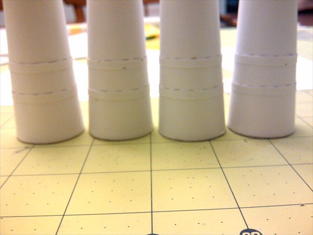
I'm guessing without, since the instructions just call for EURO GRAY all over the tanks. I had no idea there was frosting, or even what that means.
The R-7/Soyuz, same as the Atlas, uses kerosene for fuel, which of course is a room temp/atmospheric pressure liquid... BUT they use LIQUID OXYGEN for oxidizer... which at 297 degrees below zero (or thereabouts IIRC) is DEFINITELY cryogenic!
It causes the moisture in the air to freeze to the sides of the rocket on the LOX tank... as the frigid liquid inside absorbs heat from the air, through the metal tank wall, causing the LO2 to boil... (same idea as refrigeration-- the GOX (gaseous oxygen) boiled off has to be vented to the atmosphere through a pressure regulator to maintain the correct pressure in the tank, and the boiled off LO2 has to be replenished to keep the tanks "topped off" at the proper level prior to ignition and liftoff.
That's why when you see the Soyuz, Atlas, and especially the Saturn V, during ignition and liftoff, there's a virtual SNOWSTORM on the launch pad-- because the layer of frost and ice that builds up several inches thick is shaken loose and rains down the sides of the rocket onto the launch pad because of the acoustic vibrations and physical vibration of the vehicle from the turbopumps and engines when the rocket fires up. This can amount to TONS of ice and frost clinging to the sides of the rocket that come raining down like a hailstorm...
Now, Liquid hydrogen is 423 degree below zero, in fact only about 7 degrees or so above absolute zero (again IIRC). This is below the temperature at which AIR ITSELF liquifies... liquid air dribbling off the sides of the tanks and into the machinery is an explosion hazard, because liquid air may be 70-odd percent liquid nitrogen, but it's also 23 percent liquid OXYGEN, which is INCREDIBLY reactive (and bursts into flames when in contact with anything flammable if you just LOOK AT IT HARD ENOUGH! SO, special precautions were used to insulate the LH2 tanks to prevent the formation of liquid air... The original plan was to line the LH2 tanks of the Saturn V with balsa wood planking several inches thick... this evolved into special "insulation tiles" applied to the interior surfaces of the LH2 tanks, and spray-on foam insulation being used on the outside of the Saturn V S-II stage LH2 tank. Of course this also minimized boiloff of the volatile highly flammable LH2, which has to be replenished with additional liquid hydrogen before liftoff and also the GH2 has to be carried off by a vent umbilical and safely burned off, which at KSC is a "burn pond" where it is bubbled to the surface from underwater pipes, ignited, and burned off on the surface of the water as it bubbles up. (Hydrogen burns perfectly clear in air-- you cannot see the flames-- had a buddy in the police academy who got bad 3rd degree burns when he was a chemical plant fireman-- they were fighting a refinery fire and a hydrogen fireball shot straight out toward them and burned them all badly...) And of course GH2 mixed with air is somewhat explosive-- if you've ever had a car battery explode like a hand grenade right in front of you (I have, in a farm tractor) you'll know what I mean!
When the Space Shuttle came along, it was realized that it would be necessary to prevent the "ice storm" raining down the sides of the rocket that had been acceptable with Atlas and the Saturns... because the shuttle's VERY BRITTLE and easily damaged (about like sheetrock, maybe a little softer actually) thermal protection tiles were adjacent and a couple feet away from the side of the External Tank, which would be filled with LOX (in the front 'nosecone' above the SRB's) and LH2 (from the orbiter nosecap tip to the rear dome of the tank). SO, they perfected the spray-on insulation and laid it up in layers sufficient to prevent the formation of ice on the sides of the ET, so no ice could flake off at ignition and pulverize the tiles as it fell... It's still not EXACTLY perfect-- the shuttle had to have it's foam applied VERY CAREFULLY to avoid large bubbles or voids in the foam... these bubbles of trapped air on the hydrogen tank would, once the tank was full of ultra-cold LH2, the air inside the bubbles would LIQUIFY, which then created a vaccuum in the large "bubble" which the outer atmospheric pressure would then "crush" the foam down around the now much smaller volume of liquified air... which weakened the foam, it's bond to itself, and bond to the tank wall... at liftoff the liquid air would also tend to try to push out the bottom of the bubble or void, further weakening the foam, and as the ET's surface would heat to about 400 degrees F due to aerodynamic heating effects, the liquid air would then boil off from the heat and expand greatly in the thinner upper atmosphere, nearly devoid of outside pressure, which would cause the foam to break off the external tank.
As spraying on massive amounts of foam on the outside of the tank is much cheaper and easier than gluing thousands of custom-made insulation tiles to the insides of the fuel tanks, it's the same method used on other LH2 rockets like Delta IV, and the proposed SLS rocket.
SO, now ya know...
")
OL JR