You are using an out of date browser. It may not display this or other websites correctly.
You should upgrade or use an alternative browser.
You should upgrade or use an alternative browser.
What do you MPR and HPR people think of Thrust vector control
- Thread starter AndrewB
- Start date


Help Support The Rocketry Forum:
This site may earn a commission from merchant affiliate
links, including eBay, Amazon, and others.
- Joined
- Sep 20, 2017
- Messages
- 2,905
- Reaction score
- 2,986
I wanted to hear what you MPR, and HPR people think of TVC and if you think its really worth doing if its fun, Also if you will ever do it! just curious.
I did it, with the intention of flying Saturn-V on G8 motors with TVC.
Then G8's got de-certified, and now I'm am rebuilding.
I have a stash of F15 (Estes) and F10 (Apogee) motors, but the former burns too short to enjoy the flight (3.5 secs), and the latter has an average thrust of 10.6 Newtons (2.25 lbs).
My Sat-V with TVC hardware and batteries weights in at 767g, or ~1.69 lbs. And that's without fins, no escape tower, and with a minimal chute.
So assuming zero thrust vectoring, it might hit 200 feet of altitude. With active vectoring to keep it going vertical, it's more like ~150 feet.
The minimal weight of TVC hardware is ~200g.
I am rebuilding the innards to minimize weight and make for more satisfying flights.
My take on the situation - wait for more powerful long-burn motors to become availability, or build smaller/lighter rockets.
More info here: https://www.rocketryforum.com/threads/bps-space-thrust-vectoring-control-rocket-build-thread.151207/
HTH,
a
Yikes! Tvc is hard to use a lot of times, personally I havent launched yet but seen others mistakes and stuff. What do you mean by the minimal weight of tvc is 200G?I did it, with the intention of flying Saturn-V on G8 motors with TVC.
Then G8's got de-certified, and now I'm am rebuilding.
I have a stash of F15 (Estes) and F10 (Apogee) motors, but the former burns too short to enjoy the flight (3.5 secs), and the latter has an average thrust of 10.6 Newtons (2.25 lbs).
My Sat-V with TVC hardware and batteries weights in at 767g, or ~1.69 lbs. And that's without fins, no escape tower, and with a minimal chute.
So assuming zero thrust vectoring, it might hit 200 feet of altitude. With active vectoring to keep it going vertical, it's more like ~150 feet.
The minimal weight of TVC hardware is ~200g.
I am rebuilding the innards to minimize weight and make for more satisfying flights.
My take on the situation - wait for more powerful long-burn motors to become availability, or build smaller/lighter rockets.
More info here: https://www.rocketryforum.com/threads/bps-space-thrust-vectoring-control-rocket-build-thread.151207/
HTH,
a
- Joined
- Sep 20, 2017
- Messages
- 2,905
- Reaction score
- 2,986
What do you mean by the minimal weight of tvc is 200G?
TVC mount, fully assembled, with wiring harnesses plugged in: 96.3g
Signal R2 computer mounted on the brackets: 106.9g with 850 mAh battery, 56.0g without a battery.
Electronic ejection wiring, bulkhead, charge wells, and BP: I haven't measured, but at least 30-50g.
Net result: 230-250 gram / 8-9 oz of additional weight with TVC vs. flying an identical rocket without TVC.
Ahh I got ya, I personally bought someone called Deltaspacesystems TVC you can check him out on Youtube he builds and sells them too, they are definitely cheaper I think than BPS space!TVC mount, fully assembled, with wiring harnesses plugged in: 96.3g
Signal R2 computer mounted on the brackets: 106.9g with 850 mAh battery, 56.0g without a battery.
Electronic ejection wiring, bulkhead, charge wells, and BP: I haven't measured, but at least 30-50g.
Net result: 230-250 gram / 8-9 oz of additional weight with TVC vs. flying an identical rocket without TVC.
- Joined
- Jan 17, 2009
- Messages
- 5,204
- Reaction score
- 1,547
I think I might try it in 1989.
Oh, I did.")
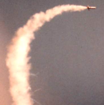
Pic of the first known successful gimbaled engine hobby rocket flight, using sunguidance. It was staged D12-0 to an upper D12 ( pieces of Thermalite in 4 directions in the upper D12 assured SOMETHING would light when the D12-0 burned thru), Only the upper stage was gimbaled, so it flew vertically, then staged. When it staged, it veered for the sun and then straightened, and then burned out and went ballistic, with a timer ejecting the chute. The camera angle made it look like it pitched sideways, but it was about 45 degrees when it straightened towards the sun. Flight two used an F15 and worked well. Remaining flights used F10 power, some went OK and others did not (part of the problem was sunguidance, and part was overcontrol)
Oh, I did.
Pic of the first known successful gimbaled engine hobby rocket flight, using sunguidance. It was staged D12-0 to an upper D12 ( pieces of Thermalite in 4 directions in the upper D12 assured SOMETHING would light when the D12-0 burned thru), Only the upper stage was gimbaled, so it flew vertically, then staged. When it staged, it veered for the sun and then straightened, and then burned out and went ballistic, with a timer ejecting the chute. The camera angle made it look like it pitched sideways, but it was about 45 degrees when it straightened towards the sun. Flight two used an F15 and worked well. Remaining flights used F10 power, some went OK and others did not (part of the problem was sunguidance, and part was overcontrol)
Hmm ive never heard of sun guidance but that is really cool! the pic looks cool even though its not that high quality looks cool! I have a tvc of my own and plan to use tvc for some HPR.I think I might try it in 1989.
Oh, I did.
Pic of the first known successful gimbaled engine hobby rocket flight, using sunguidance. It was staged D12-0 to an upper D12 ( pieces of Thermalite in 4 directions in the upper D12 assured SOMETHING would light when the D12-0 burned thru), Only the upper stage was gimbaled, so it flew vertically, then staged. When it staged, it veered for the sun and then straightened, and then burned out and went ballistic, with a timer ejecting the chute. The camera angle made it look like it pitched sideways, but it was about 45 degrees when it straightened towards the sun. Flight two used an F15 and worked well. Remaining flights used F10 power, some went OK and others did not (part of the problem was sunguidance, and part was overcontrol)
H_Rocket
Death by Powerpoint
It's kind of neat, however there are not enough mid power and high power motor choices to make it anything that will gain widespread interest.
Do you mean their arent enough Thrust vector controlling devices that can handle mid, and high power motor?It's kind of neat, however there are not enough mid power and high power motor choices to make it anything that will gain widespread interest.
- Joined
- Jan 17, 2009
- Messages
- 5,204
- Reaction score
- 1,547
Keep in mind that pic was taken 31 years ago. I have some video of the 1989 gimbaled project I've meant to edit together and put on Youtube.Hmm ive never heard of sun guidance but that is really cool! the pic looks cool even though its not that high quality looks cool! I have a tvc of my own and plan to use tvc for some HPR.
Here's some more about sunguidamce.
https://georgesrockets.com/GRP/RandD/Sunguidance.htm
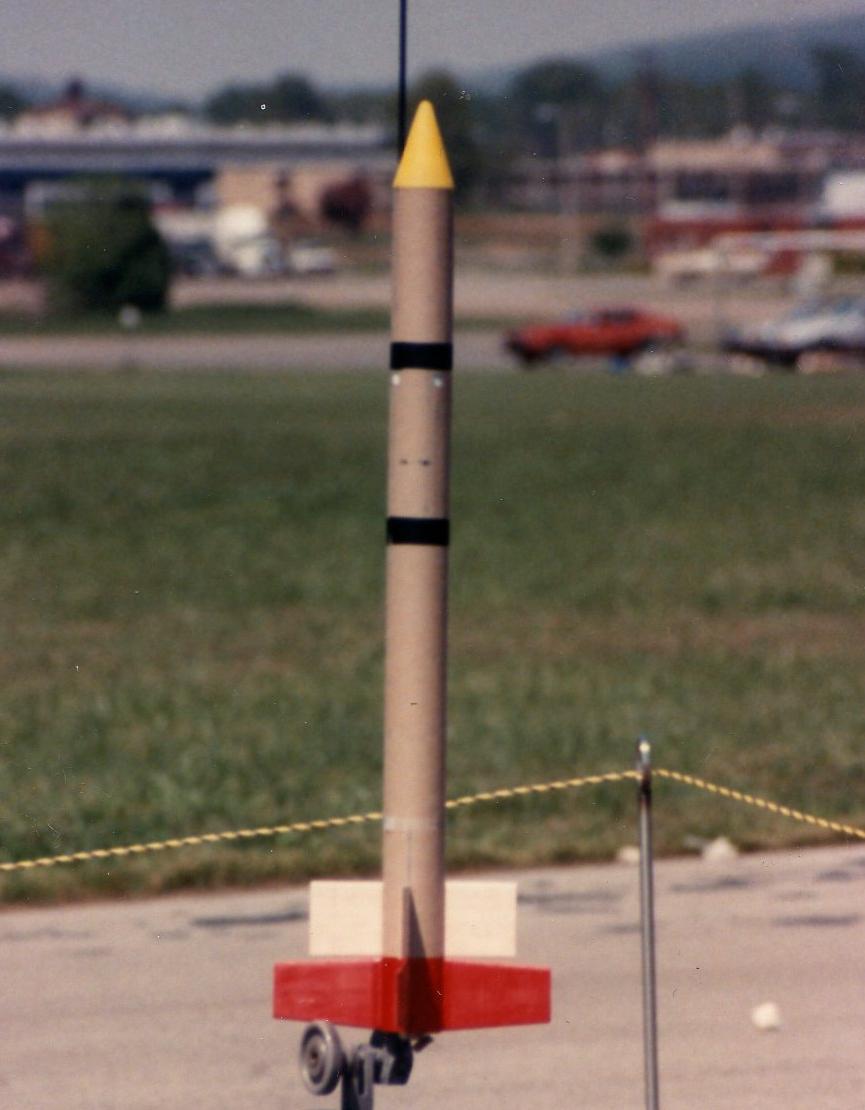
Here's some more pics from the 1989 Gimbaled engine project. First is the 2-stage prototype, where the booster was not gimbaled. Note some little white rectangles under the top-most wrap of black tape. Those were where the sungiuidance light sensors were mounted. That proved to cause too much over-control on sunny days.
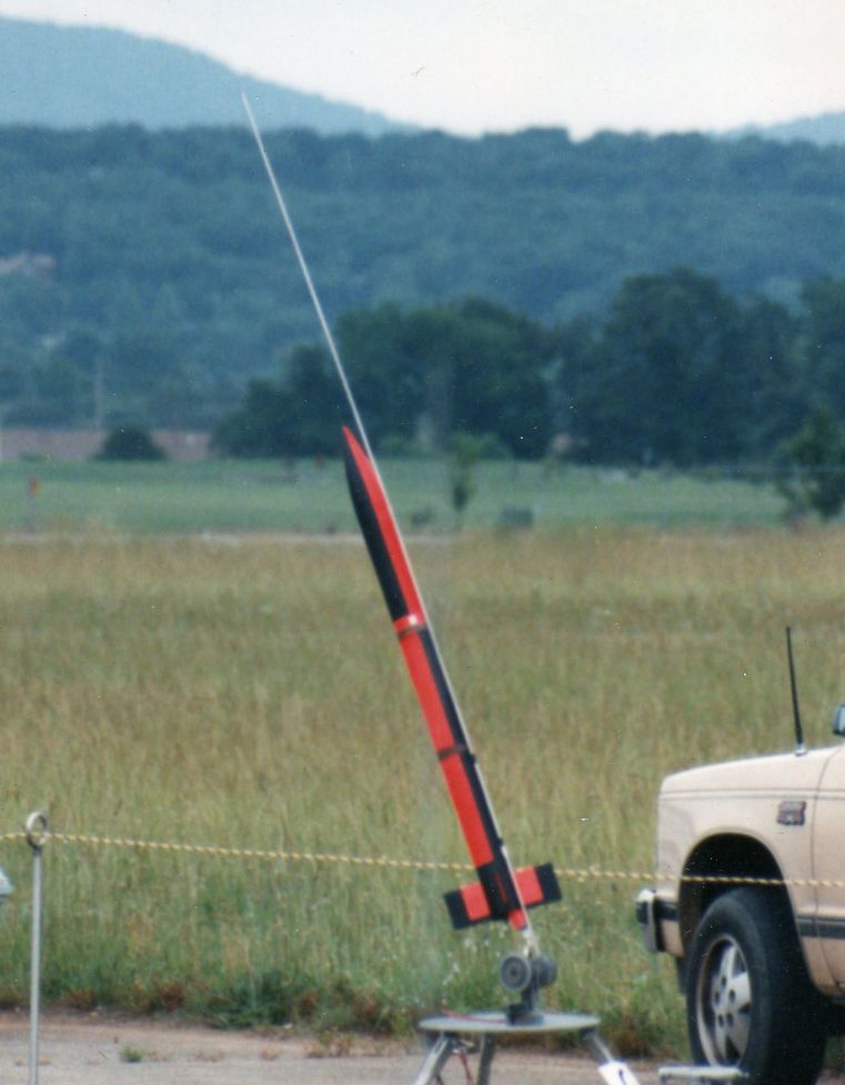
The model shortly before flight #2, which was on an Aerotech F15. The flight worked great, the overcast sky kept it from over controlling. Launched it at an angle since the only way to test the gimbal guidance actually worked =, due to the overcast sky, was to angle it. Sunguidance steers vertically when the sky is overcast, and it did straighten up and fly vertically. The rest of the flights used F10 motors, F15 was more thrust than needed and only 5.5 second burn compared to 8 seconds for the F10.
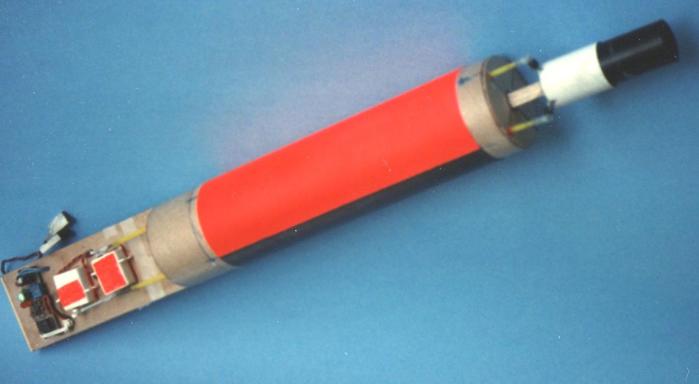
The test model was made out of Estes BT-80 (2.6" tubing), and was designed to be modular. Sections that slipped together, held together with wraps of tape. The fin assembly was removable for access and to allow changing the fin configurations. The assembly in this image was the core of the whole model, gimbal mount at bottom, servos and electronics on a board at the top. There were plug-in wiring connectors to hook up to the sunguidance light sensors and the electronic ejection charge (When the motor ignited, it burned a thin wire which allow an electronic timer to start, to fire the ejection at the programmed time. The ejection worked every time)
Close-up of the gimbal mount. Totally unlike the TVC mounts used today. A ball and socket gimbal joint, at the top of the mount. The pushrods used Du-Bro Ball Links, to allow for connections to control arms that needed 2-axes of pivoting (originally used for R/C helicopter pushrods)
thanks for sharing the photos and the story, I find that really interesting that it was the first TVC launched back 31 years ago!!! I shared it with my friends they think it is interesting and pretty cool. I also shared photos etc! thanks.Keep in mind that pic was taken 31 years ago. I have some video of the 1989 gimbaled project I've meant to edit together and put on Youtube.
Here's some more about sunguidamce.
https://georgesrockets.com/GRP/RandD/Sunguidance.htm
Here's some more pics from the 1989 Gimbaled engine project. First is the 2-stage prototype, where the booster was not gimbaled. Note some little white rectangles under the top-most wrap of black tape. Those were where the sungiuidance light sensors were mounted. That proved to cause too much over-control on sunny days.
The model shortly before flight #2, which was on an Aerotech F15. The flight worked great, the overcast sky kept it from over controlling. Launched it at an angle since the only way to test the gimbal guidance actually worked =, due to the overcast sky, was to angle it. Sunguidance steers vertically when the sky is overcast, and it did straighten up and fly vertically. The rest of the flights used F10 motors, F15 was more thrust than needed and only 5.5 second burn compared to 8 seconds for the F10.
The test model was made out of Estes BT-80 (2.6" tubing), and was designed to be modular. Sections that slipped together, held together with wraps of tape. The fin assembly was removable for access and to allow changing the fin configurations. The assembly in this image was the core of the whole model, gimbal mount at bottom, servos and electronics on a board at the top. There were plug-in wiring connectors to hook up to the sunguidance light sensors and the electronic ejection charge (When the motor ignited, it burned a thin wire which allow an electronic timer to start, to fire the ejection at the programmed time. The ejection worked every time)
Close-up of the gimbal mount. Totally unlike the TVC mounts used today. A ball and socket gimbal joint, at the top of the mount. The pushrods used Du-Bro Ball Links, to allow for connections to control arms that needed 2-axes of pivoting (originally used for R/C helicopter pushrods)
DaveW6DPS
Well-Known Member
Thrust vector control seems to be the "in style" thing now. For practical reasons I am looking at using control surfaces.
On a typical HPR flight you have only a few seconds of thrust to vector.
With control surfaces as long as you have appreciable forward movement you can have control.
But vectoring thrust just sounds so much more nerdy!
On a typical HPR flight you have only a few seconds of thrust to vector.
With control surfaces as long as you have appreciable forward movement you can have control.
But vectoring thrust just sounds so much more nerdy!
H_Rocket
Death by Powerpoint
Do you mean their arent enough Thrust vector controlling devices that can handle mid, and high power motor?
No, there are not enough HPR motors with long enough a burn time to make it worth the effort. Of course that is my $0.02 an YMMV.
got ya, I recommend the I65 is is a pretty high power motor and with a 8 second burn time. But I do agree in way with that statement!No, there are not enough HPR motors with long enough a burn time to make it worth the effort. Of course that is my $0.02 an YMMV.
Correct, because it is. Haha its fun to do though if you build your own its really fun also you can redesign easily because all the parts are pretty much 3d printed and are cheap. Its the servos and electronic's that cost a chunk of money. I encourage everyone to give it a shot. Build your own its fun and worth it!Thrust vector control seems to be the "in style" thing now. For practical reasons I am looking at using control surfaces.
On a typical HPR flight you have only a few seconds of thrust to vector.
With control surfaces as long as you have appreciable forward movement you can have control.
But vectoring thrust just sounds so much more nerdy!
Keep in mind that pic was taken 31 years ago. I have some video of the 1989 gimbaled project I've meant to edit together and put on Youtube.
Here's some more about sunguidamce.
https://georgesrockets.com/GRP/RandD/Sunguidance.htm
Here's some more pics from the 1989 Gimbaled engine project. First is the 2-stage prototype, where the booster was not gimbaled. Note some little white rectangles under the top-most wrap of black tape. Those were where the sungiuidance light sensors were mounted. That proved to cause too much over-control on sunny days.
The model shortly before flight #2, which was on an Aerotech F15. The flight worked great, the overcast sky kept it from over controlling. Launched it at an angle since the only way to test the gimbal guidance actually worked =, due to the overcast sky, was to angle it. Sunguidance steers vertically when the sky is overcast, and it did straighten up and fly vertically. The rest of the flights used F10 motors, F15 was more thrust than needed and only 5.5 second burn compared to 8 seconds for the F10.
The test model was made out of Estes BT-80 (2.6" tubing), and was designed to be modular. Sections that slipped together, held together with wraps of tape. The fin assembly was removable for access and to allow changing the fin configurations. The assembly in this image was the core of the whole model, gimbal mount at bottom, servos and electronics on a board at the top. There were plug-in wiring connectors to hook up to the sunguidance light sensors and the electronic ejection charge (When the motor ignited, it burned a thin wire which allow an electronic timer to start, to fire the ejection at the programmed time. The ejection worked every time)
Close-up of the gimbal mount. Totally unlike the TVC mounts used today. A ball and socket gimbal joint, at the top of the mount. The pushrods used Du-Bro Ball Links, to allow for connections to control arms that needed 2-axes of pivoting (originally used for R/C helicopter pushrods)
if you dont mind I tweeted this out and gave pics and credit to you! I really like how retro this tvc is awesome!
@georgegassawayif you dont mind I tweeted this out and gave pics and credit to you! I really like how retro this tvc is awesome!
he responded with this!
@georgegassaway
he responded with this

In the future, best not to do this without asking *in advance*.if you dont mind I tweeted this out and gave pics and credit to you! I really like how retro this tvc is awesome!
- Joined
- Jan 17, 2009
- Messages
- 5,204
- Reaction score
- 1,547
Fine with me. I expect any messages I post to be likely to show up somewhere else.
george, I have a question not involving this particular thread but a question on how to get into contact with my local tripoli club. I went on the map finder and sent a message but havent got a respons for some time nowFine with me. I expect any messages I post to be likely to show up somewhere else.
- Joined
- Jan 17, 2009
- Messages
- 5,204
- Reaction score
- 1,547
Not a member of Tripoli, been in the NAR since 1970.
Here's a few more images from the 1989 gimbaled engine model. This shows the engine mount by itself. The Du-Bro ball is embedded into epoxy at the top of the motor mount. I put a bit of vaseline on it before putting it into the epoxy. Once cured, the epoxy held it in place (as a socket) but it pivoted freely. Two threaded rods at 90 degrees for pitch and yaw control horns. One has a ball link attached, the other not yet. There were a few occasions that on landing, the epoxy broke and I had to swap out a spare engine mount.
I tried some ways to address the problem of aerodynamic forces causing thrust vectoring to be less effective at higher speeds. This one, the fixed fin size was cut in half, and the half of the area that was removed was glued to the engine mount. So, as the mount moved, it was also causing aerodynamic control forces. The Redstone rocket, it literally had a chain and sprocket drive system, so as the thrust vector control vanes moved, the "air rudders" on the fin tips also moved to provide aerodynamic steering.
And.... this. No fixed surfaces at all, the entire fin assembly moving with the engine mount. Also a good view of the nylon ball sockets and pushrods connected to the mount.
Same as above, but with cut-out BT-80 to cover over most of the tail while having slots cut in to allow for fin motion.
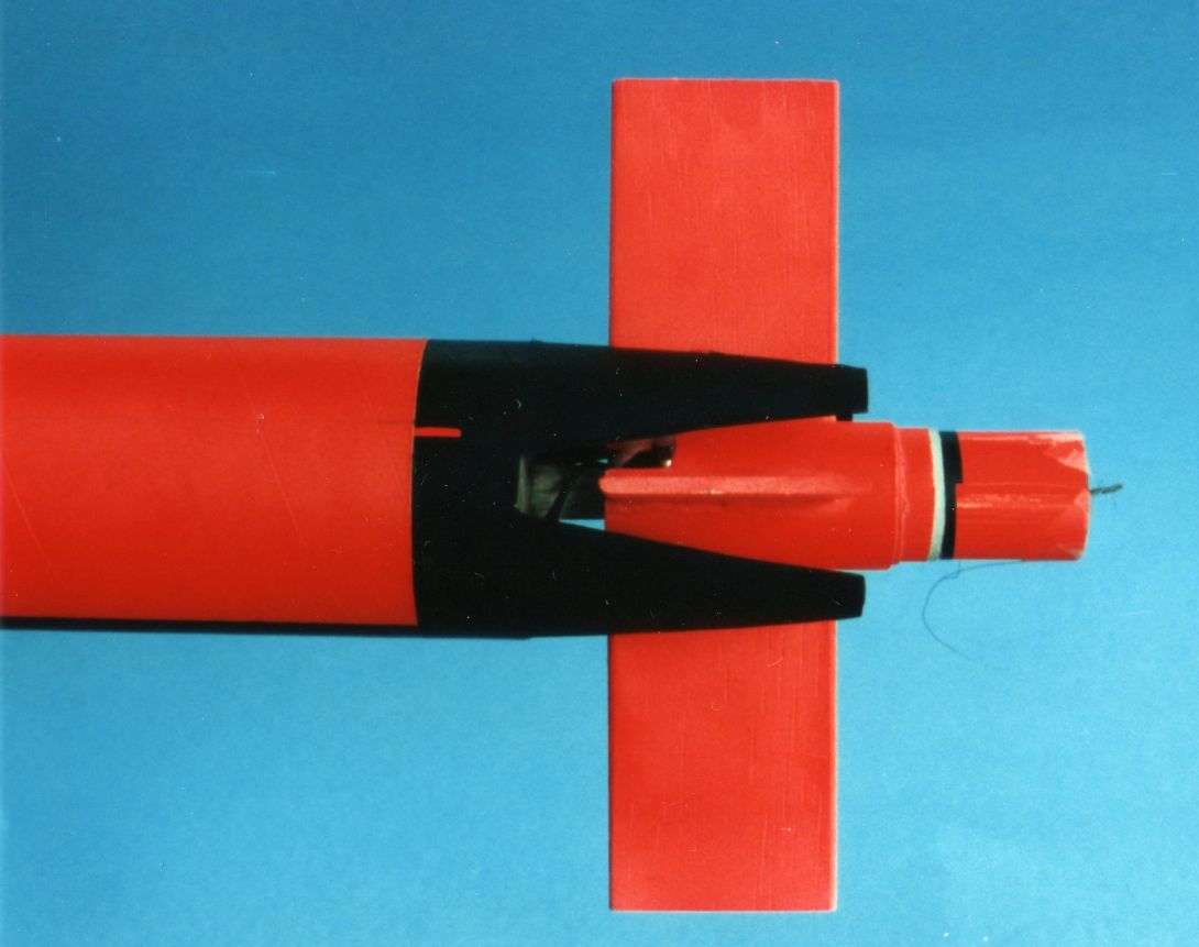
BTW - to jump over to another post, in MOST cases, aerodynamic control surfaces are better in general. TVC rockets need relatively low thrust and long burn to be worth doing. High thrust with high speed is very bad for TVC, can over-control too easily. And simply not as impressive as seeing a very long burn SLOW climb that does not veer off course like weathercocking. If you want a rocket model to be using guidance beyond say 1000 feet up, it really needs to be using aerodynamic control surfaces, not TVC.
Here's a few more images from the 1989 gimbaled engine model. This shows the engine mount by itself. The Du-Bro ball is embedded into epoxy at the top of the motor mount. I put a bit of vaseline on it before putting it into the epoxy. Once cured, the epoxy held it in place (as a socket) but it pivoted freely. Two threaded rods at 90 degrees for pitch and yaw control horns. One has a ball link attached, the other not yet. There were a few occasions that on landing, the epoxy broke and I had to swap out a spare engine mount.
I tried some ways to address the problem of aerodynamic forces causing thrust vectoring to be less effective at higher speeds. This one, the fixed fin size was cut in half, and the half of the area that was removed was glued to the engine mount. So, as the mount moved, it was also causing aerodynamic control forces. The Redstone rocket, it literally had a chain and sprocket drive system, so as the thrust vector control vanes moved, the "air rudders" on the fin tips also moved to provide aerodynamic steering.
And.... this. No fixed surfaces at all, the entire fin assembly moving with the engine mount. Also a good view of the nylon ball sockets and pushrods connected to the mount.
Same as above, but with cut-out BT-80 to cover over most of the tail while having slots cut in to allow for fin motion.
BTW - to jump over to another post, in MOST cases, aerodynamic control surfaces are better in general. TVC rockets need relatively low thrust and long burn to be worth doing. High thrust with high speed is very bad for TVC, can over-control too easily. And simply not as impressive as seeing a very long burn SLOW climb that does not veer off course like weathercocking. If you want a rocket model to be using guidance beyond say 1000 feet up, it really needs to be using aerodynamic control surfaces, not TVC.
Last edited:
- Joined
- Jan 17, 2009
- Messages
- 5,204
- Reaction score
- 1,547
BTW - a lot of people did TVC guidance thru the years, some pretty neat ones in the 1990's. And some began ot use microcontrollers and more recently Arduino-types.
But I wanted to include this video of Alyssa Stenberg's 2013 R&D project. She tested out using a model airplane autopilot for vertical flight. The Eagle Tree Guardian autopilot. It proved to be very well suited as a hobby rocket guidance system. She did a lot of tests with aerodynamic control surfaces. And also several gimbaled engine flights using G12 reloads in a BT-101 (4") diameter rocket about 5 feet tall. Here is video by Chris Taylor of her presentation, which included video of her flights. On some of the gimbaled flights, she added a few ounces of ballast. When some say it's not possible to fly TVC larger than 2.6" diameter on motors like the G12, I say B.S. Note how impressive the slow boosting gimbaled flights are. I will note the two finless flights wobbled a bit, it is asking a lot of a model guidance system to keep an unstable rocket to fly steadily. For the gimbaled mount, she used an R/C Car driveshaft universal joint for the pivot.
But I wanted to include this video of Alyssa Stenberg's 2013 R&D project. She tested out using a model airplane autopilot for vertical flight. The Eagle Tree Guardian autopilot. It proved to be very well suited as a hobby rocket guidance system. She did a lot of tests with aerodynamic control surfaces. And also several gimbaled engine flights using G12 reloads in a BT-101 (4") diameter rocket about 5 feet tall. Here is video by Chris Taylor of her presentation, which included video of her flights. On some of the gimbaled flights, she added a few ounces of ballast. When some say it's not possible to fly TVC larger than 2.6" diameter on motors like the G12, I say B.S. Note how impressive the slow boosting gimbaled flights are. I will note the two finless flights wobbled a bit, it is asking a lot of a model guidance system to keep an unstable rocket to fly steadily. For the gimbaled mount, she used an R/C Car driveshaft universal joint for the pivot.
Last edited:
BTW - a lot of people did TVC guidance thru the years, some pretty neat ones in the 1990's. And some began ot use microcontrollers and more recently Arduino-types.
But I wanted to include this video of Alyssa Stenberg's 2013 R&D project. She tested out using a model airplane autopilot for vertical flight. The Eagle Tree Guardian autopilot. It proved to be very well suited as a hobby rocket guidance system. She did a lot of tests with aerodynamic control surfaces. And also several gimbaled engine flights using G12 reloads in a BT-101 (4") diameter rocket about 5 feet tall. Here is video by Chris Taylor of her presentation, which included video of her flights. On some of the gimbaled flights, she added a few ounces of ballast. When some say it's not possible to fly TVC larger than 2.6" diameter on motors like the G12, I say B.S. Note how impressive the slow boosting gimbaled flights are. I will note the two finless flights wobbled a bit, it is asking a lot of a model guidance system to keep an unstable rocket to fly steadily. For the gimbaled mount, she used an R/C Car driveshaft universal joint for the pivot.
Thats really awesome! "When some say it's not possible to fly TVC larger than 2.6" diameter on motors like the G12, I say B.S. " I totally agree with that statement. the fact that im currently building a tvc for a I65 motor and that has a rocket diameter of 7.51 inches. Its possible, just a LOT of testing im sure you would know that
TVC is definitely costly but worth it to me. thanks for all the info George you included some great pictures and videos. If you wanna include more that would be great! If you want updates on my TVC development I might post them on my personal Youtube channel for fun, not for views or fame just for fun. tell me if you want the link to it this project im estimating will take a year or a little more not sure but it will be fun!For those who want to be even more nerdy, I have an off the wall suggestion: pop-out fins. Use TVC for a slow, majestic liftoff. Then just before burnout release the spring loaded fins that keep it stable for a good coast.
I literally wanted to do that and thought of that idea a day ago until I found the motor the I65 it has like a 7-8 second burn time. But in the future I am totally doing that and the fins might be Arduino controlledFor those who want to be even more nerdy, I have an off the wall suggestion: pop-out fins. Use TVC for a slow, majestic liftoff. Then just before burnout release the spring loaded fins that keep it stable for a good coast.
Flyfalcons
Well-Known Member
- Joined
- Apr 14, 2015
- Messages
- 2,584
- Reaction score
- 912
I think for our flight profiles, it is pointless.
I think for our flight profiles, it is pointless.
"Because it's there" - Sir Edmund Hillary
Reinhard
For those who want to be even more nerdy, I have an off the wall suggestion: pop-out fins. Use TVC for a slow, majestic liftoff. Then just before burnout release the spring loaded fins that keep it stable for a good coast.
Might be a good use for grid fins.
yeah, I decided to test out those and im currently making them in CAD right now. But grid fins can sometimes not be as effective as fins by a whole lot.Might be a good use for grid fins.
- Joined
- Jan 17, 2009
- Messages
- 5,204
- Reaction score
- 1,547
The very nature of a slow majestic climb on a long burn motor is that there's not going to be a lot of velocity. Such that once the motor burns out, it's not going to coast up very far. Pop-out fins just not worth the hassle for such a short coast. dFor those who want to be even more nerdy, I have an off the wall suggestion: pop-out fins. Use TVC for a slow, majestic liftoff. Then just before burnout release the spring loaded fins that keep it stable for a good coast.
Also, TVC models fly best when they are a BIT aerodynamically stable, and err on the side of more stable than not stable. Rewatch Alyssa Stenberg's video of the gimbaled engine tests. Only two were finless, and they wobbled on boost (a precession). The ones with fins, where it was positively stable, no precession and any wobbling was minor reactions to TVC control, not aerodynamic related. There were a couple of flights, at least, where the stability was too much, where as it got faster, the stability forces fought against the steering corrective forces. So this is why I say a bit stable and not fast.
Even an I-65 is going to go too fast, because it is not an endburner type thrust curve. It is a regressive burn that simply lasts a long time, and the first half of that burning is going to make it fly very fast. The last half of the burn will produce less and less TVC control forces due to less and less thrust. Here i a comparison of the I-65 and G12 thrust curves. That I-65 thrust curve shape is bad for TVC, more suited for aerodynamic control.
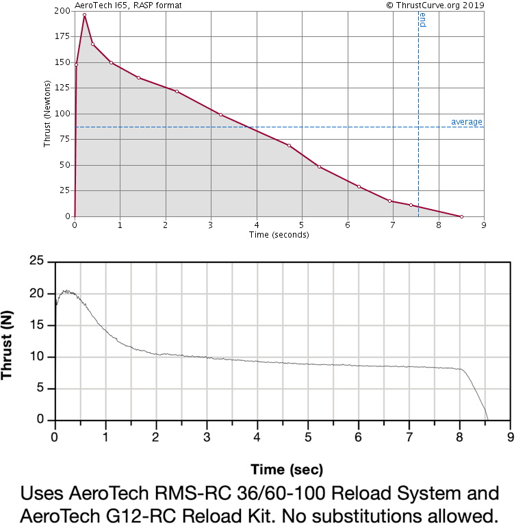
Take note that Joe Barnard's latest model, Sprint, does have fins. Also, note on this flight how later in the burn it begins to slow while thrusting, and there is almost no "coast" from burnout to apogee. There is a fact about resin nozzle as Aerotech uses, that the nozzle throat erodes. As it erodes, chamber pressure drops, so thrust drops (you can see that in the G12 thrust curve above. The slight thrust drop from about 2.5 seconds to 8 seconds is nozzle throat erosion). To prevent that, would require solid machined graphite nozzles, which have gone out of favor due to cost to fabricate (Machined one by one rather than injection mold mass production. Also cheaper material cost)
Similar threads
- Replies
- 60
- Views
- 3K
- Replies
- 52
- Views
- 2K