Level 3 Build Thread -- Velociraptor REX

The Rocketry Forum

Help Support The Rocketry Forum:

This site may earn a commission from merchant affiliate links, including eBay, Amazon, and others.
Very Nice Biuld, I know it's a lot of work!
Plus posting it!! Thanks letting us watch

I rate this Thread BaddAzz!!!
 
Like the profile on these fins--nice touch.

Very Nice Biuld, I know it's a lot of work!
Plus posting it!! Thanks letting us watch

I rate this Thread BaddAzz!!!

Thanks, guys. I realize there are a ton of high resolution photos in this thread and it can be somewhat cumbersome to wade through them all. I'm hoping that the photos and descriptions may give someone scratch building their next rocket some ideas as to how they could approach a particular task or problem.

Thanks to those who have hung with this thread thus far.
 
I mounted the talon fins dry at first. I mixed some epoxy and spread a thin layer on the roughened forward eight inches of the fincan airframe. I then slid the 16" long coupler into the airframe until it just reached the forward end of the talon fin slots. All three talon fins were inserted and the coupler was slid back into the fin tab slots cut before, locking the talon fins in place.
DSC5388-XL.jpg


This photo shows the talon fins from the inside, showing the coupler tube inserted into the fin tab.
DSC5389-XL.jpg


Although the fins were probably well enough attached by the coupler tube alone to just put fillets on, I wanted to be more certain that they weren't going anywhere under thrust. I learned my lesson with using the hardwood square stock to make the fin pockets. I picked up some basswood square stock and cut it the length of the portion of the fin tab aft of the coupler. Then I paired them and sanded them to the inside contour of the airframe. It sanded a ton more easily than the hardwood did.:D

I then epoxied the contoured strips to the airframe and fin tab as shown below:
DSC5394-XL.jpg


All three fin attachments were reinforced in this manner. If these fins come out, there will be more important problems to worry about.
DSC5398-XL.jpg


There was only one more step to complete the inner portions of the fincan. I wanted a zipperless design, so I chose to place a bulkhead near the forward end of the coupler tube.

First, I needed to make the bulkhead. All bulkheads were made from two thicknesses of 3/16" aircraft plywood and a single thickness of 1/8" G10. The G10 provides extra strength and is located on the parachute side of the bulkheads, making cleanup of black powder residue much easier. This picture shows that I went a little crazy clamping the three parts of three bulkheads together while the epoxy cured.:eek:
DSC5204-XL.jpg


Once the epoxy cured, I drilled five holes in the fincan bulkhead. Four were to accommodate two 5/16" stainless steel U-bolts. The fifth was drilled in the center of the bulkhead to accept a 3/8" diameter allthread. This was used to provide extra motor retention. Once the motor is built, a piece of 3/8" allthread will be threaded into the tapped forward closure of the motor and passed through the hole in the bulkhead. A washer and nut will hold the allthread in place, adding strength to the the bulkhead during parachute deployment and providing another source of attachment for the motor.

This photo shows the aft side of the bulkhead. The hole in the wood portion of the bulkhead is flared to make it easier to slide the allthread through when loading the motor. Since I don't plan to ever see this side of the U-bolts again, the u-bolts were secured with lock washers, lock nuts, and epoxy.
DSC5401-XL.jpg


Here is the forward side of the bulkhead.
DSC5402-XL.jpg


The bulkhead was inserted into the coupler tube far enough that the u-bolts were completely recessed into the coupler. I learned the hard way on the Avenger last year that having the u-bolt stick out from the coupler makes it so you can't stand the rocket up on the coupler because the u-bolts are in the way.:rant: A generous fillet was then applied.
 
The Performance Rocketry nosecones come without a bulkhead. This is actually pretty convenient because it keeps me from having to remove whatever bulkhead or attachment point a manufacturer uses so I can install what I actually want (like U-bolts).

I wanted to mount my Beeline GPS transmitter in the nosecone as I was unsure how well signal would transmit through the graphite in the Profusion fiberglass airframe. I didn't want to deal with attenuation and was too lazy to actually test it. Here is the nosecone and the 900mHz transmitter along with the 2" PVC plumbing I used to make a transmitter bay.
DSC5129-XL.jpg


I installed two centering rings onto the PVC pipe before gluing the connections on each end. The lower centering ring in this picture is the same construction as my other bulkheads (two layers of 3/16" aircraft plywood and one layer of 1/8" G10). It was drilled to accommodate two 5/16" stainless u-bolts. The forward centering ring (top one in this picture) was made from the original 1/4" x2 fiberglass-reinforced centering ring material that I made before.
DSC5160-XL.jpg


Here is the side view of the assembly. The centering ring on the left in this photo butts against the cap while the one on the right was cut to slide actually onto the threaded fitting. The holes in the forward centering ring were to allow foam to pass through the ring.
DSC5163-XL.jpg


The centering rings were attached to the PVC using epoxy and chopped fiber-reinforced fillets.
DSC5167-XL.jpg


The assembly was ready to install in the nosecone. As I stated earlier, I was not comfortable using the Performance nosecone without reinforcement with two-part foam. I first filled the nosecone tip with several small pours of foam, allowing partial cure before the next pour. Once the cured foam was near the level where I wanted to install the forward centering ring, I mixed a larger batch of foam. I inserted the tracker tube/centering ring assembly partway into the nosecone, then poured the foam in all at once. I then seated the tracker tube assembly in its final location and allowed the foam to cure. Again, I made sure that the U-bolts were recessed far enough that they did not interfere with standing the nose cone on end.

Holes were drilled on either side of the bulkhead and more foam was poured into the space between the rings. Once the space was fully filled, a generous milled fiber-reinforced fillet was applied, covering the holes and providing extra strength. This resulted in a rock-solid nosecone and bulkhead assembly with transmitter bay.
DSC5298-XL.jpg
 
The avionics bay for this rocket is made from a 16" coupler section that separates and connects the two parachute bays. In order to better seal the AV bay from ejection gasses, I like to place wide-bore centering rings slightly recessed from the ends of the bay.
DSC5282-XL.jpg


These rings were filleted on the interior joint only.
DSC5281-XL.jpg


I then cut gaskets from 1/8" thick adhesive-backed neoprene.
DSC5283-XL.jpg


The gaskets were then placed on the centering rings.
DSC5292-XL.jpg


The centering rings are placed deep enough from the end of the tube that the inner 3/16" bulkhead disk compresses the neoprene and fully seals the bay. The other 3/16" plywood and 1/8" G10 bulkheads are cut to the outside diameter of the tube. This design provides a very good seal and lends excellent strength to pull-through of the avionics sled through the bay during deployment.
DSC5291-XL.jpg


The necessary holes were drilled in both bulkheads at once, ensuring everything lined up correctly. Here, four holes have been drilled for the four allthread pieces that will hold the bay together. One of the two U-bolts is placed temporarily. By filling each hole as it is drilled, accurate alignment is maintained.
DSC5316-XL.jpg


The laser crosshair guide on my drill press really makes it easier to get the holes where I want them.
DSC5317-XL.jpg


Here are the drilled AV bay bulkheads. There are four holes for the 1/4" allthread, two holes for each of the two 5/16" U-bolts, one hole for each of the two Blastcap charge holders, and two holes for the brass screw e-match terminals. The holes in the centers were from the circle cutting jig guide pins and were filled with epoxy to prevent ejection gasses from passing through them. The holes look confusing right now but will make more sense in the next post.
DSC5322-XL.jpg
 
As promised in the last post, this post will make all those holes in the AV bay bulkheads make a little more sense (I hope).

First, this is a view of the forward (main parachute bay) bulkhead. The holes are now filled with their appropriate screws, so I hope this is more clear. Shown are the four 1/4" stainless allthread sections with fender washers and locknuts, two 5/16" stainless U-bolts, two Large Blastcap charge holders, and two sets of brass screws with knurled nuts for attaching e-matches.
DSC6974-XL.jpg


This photo shows the other side of the bulkhead. Shown are the two sets of wires leading from the electronics to the brass screws. This arrangement allows easy, tool less hook-up of e-matches without risk of leakage of black powder residue through the bulkhead. Also shown is the top of the battery cover. It is set away from the bulkhead with plastic spacers. When the nuts are tightened on the bulkhead, it compresses the cover tightly onto the battery compartment.
DSC6980-XL.jpg


Here is the view from on top of the battery compartment cover. The open notches on either side were originally cut to accommodate the backs of the U-bolts, but were not necessary once the plastic spacers were added. The twisted and shrink-wrapped wires from the electronics to the bulkhead pass through the cover.
DSC6983-XL.jpg


This photo shows the batteries in the battery compartment with the (loosened) cover over them.
DSC6984-XL.jpg


Here, the battery compartment cover has been removed. The batteries are nicely contained in heavy-duty nylon holders. The bottom of the compartment cover is covered with 1/8" thick neoprene. This is compressed over the batteries, holding them firmly in place.
DSC6985-XL.jpg


Here the batteries are seated in the heavy-duty nylon holders and held in place firmly with heavy-duty zip-ties. The zip-ties are likely superfluous as the batteries are held tightly in their holders by the design of the compartment, but they do provide one more reassurance that the electronics will not lose power during flight. As the photo shows, the charge wires pass through the battery holder into the electronics area on the right side of the photo while the battery wires pass through on the left side. The negative wire to the top battery is blue because it comes directly from the R-DAS wiring harness.
DSC6988-XL.jpg
 
This photo shows the rather spartan interior of the avionics bay. A single sled was placed over two of the four sections of allthread. The sled is attached to the allthread with sections of carbon fiber arrow shaft. It is a nice fit over the allthread, is lightweight, and epoxies more securely to the sled than brass tubing does. By cutting the arrow shaft sections longer than the sled, I can secure the sled in place using nuts, keeping it from sliding around. Also shown in this photo is the ejection charge wiring leading to the main parachute bay (on the left) and the drogue bay (on the right). I use a wiring convention that makes sense to me: white leads to the main bay while yellow goes to the drogue bay. The brown wires represent the leads from the MARSA4 (primary) altimeter and the purple wires represent the leads from the Raven (secondary) altimeter.
DSC6989-XL.jpg


Here is a view of the altimeter-side of the sled. The forward end is up in this photo. Shown are the three altimeters (MARSA4, Raven, and an R-DAS Tiny flying in record-only mode just for fun). The three push buttons on the top portion of the sled are from Radio Shack. They are simple push on, push off switches with a tactile and audible click when they are pushed.
DSC6991-XL.jpg


Here is a close-up of the MARSA4 and the Raven. The wires passing through the sled are protected by heat shrink wrap and rubber gaskets. I like to have the wires on the opposite side of the sled to keep the electronics side uncluttered. The brass screw just in front of the Raven is used to connect the common leads for the Raven.
DSC6995-XL.jpg


Here is a close-up of the buttons. I have used these on all my projects. They allow me to arm the electronics using a wooden dowel through a sample port. No fishing around for screw terminals inside the rocket, no switch band on the outside of the rocket, no wires twisted together and either pushed inside or taped outside. Just a clean look and easy arming.
The wires on the right side of this photo are the power leads from the R-DAS. I simply removed the rest of the wires from the harness to keep things cleaner.
DSC6999-XL.jpg


Here is a shot of the back side of the sled. The switches have several different wires coming off them. The lower switch in this photo is from the MARSA4 (remember, brown wires mean MARSA4). The middle switch is the hot wire for the Raven from the battery straight to the common post (the brass screw in the bottom right-corner). The purple wire on the uppermost switch is the positive lead from the R-DAS. The black wire running between two of the switches is actually the antenna from my CSI radio tracker transmitter.
DSC7001-XL.jpg


Here is a photo showing the radio transmitter. This comes in a nifty clam shell setup. I purchased a bunch of the bases and epoxy them onto the sled or to a piece of G10 I can attach to the sled. Then I secure the top on with zip-ties (just to keep the clam shell from coming apart -- it does not take any downward force at launch).
DSC7002-XL.jpg


This is the way I attach my charge wires to the aft (drogue bay) bulkhead. All four wires are secured in a Molex connector (again, yellow for drogue, purple for Raven, brown for MARSA4).
DSC7003-XL.jpg


Here is the base of the aft bulkhead with the opposite Molex connector. The connector is secured in place with epoxy and a strip of fiberglass for reinforcement. It is attached to the wires that lead to the brass screw terminals, identical to the forward bulkhead.
DSC7004-XL.jpg


Here I've connected the two halves. This would normally be done after the forward part of the sled was inserted through the avionics bay. The extra wire length allows me to connect the aft bulkhead. then slide the bulkhead onto the allthread. The white clip in this picture was used for extra strain relief during flight, but probably is not necessary.
DSC7005-XL.jpg
 
Large external fillets were then applied. To get pretty even fillets, I first marked the fin and body tube using a piece of rectangular stock as a guide.
DSC5404-XL.jpg


Blue painters tape is applied to the fins and body tube and epoxy mixed with West System Filleting Blend to a peanut-butter consistency is applied. A cylindrical object of the right diameter is dipped in alcohol and pulled across the filet, removing the excess epoxy and pushing it onto the tape, which is then removed. A more detailed set of photos of this step is shown in my Avenger build. For this build, a dead D-cell battery was just about the right diameter for this purpose. This photo shows the battery in relation to the now cured epoxy with the tape removed.
DSC5431-XL.jpg


After the epoxy reached the leathery stage, the tape is removed and the fillet is smoothed using a gloved finger dipped liberally in alcohol.
DSC5430-XL.jpg


I like to gently taper the forward and aft ends of the fillet to make them pretty.
DSC5433-XL.jpg


With the epoxy fully cured, I used a dowel wrapped with sandpaper to take down the high spots and improve the smoothness of the fillet. At one point I purchased dowel in a bunch of different diameters and cut a small section of of each of them. Now I just grab one that is about the right diameter, wrap it with sandpaper, and go. Saves me from hunting around for something that's just the right diameter around the house.
DSC5435-XL.jpg


As you can see, I continued to use the fin alignment jig as a stand through much of this build.

Once the rough sanding was finished, I filled the fillets, fins, and any defects in the fiberglass (thank goodness--no spiral grooves:D) with Bondo glazing putty and sanded with 220 grit and 320 grit sandpaper.
 
Before I got too carried away with finish work, I went ahead with ground testing. This was the biggest and by far the heaviest rocket I have built to date. Here, the object for the drogue charge is to get some separation, not to send the entire rocket shooting across the grass.
DSC5458-XL.jpg


I used Vern Knowles' ejection charge calculator https://vernk.com/EjectionChargeSizing.htm to estimate the primary drogue charge at 3.5g black powder. This was the result of that charge. There is a clean shearing of the six 4-40 nylon shear pins and clean separation of the two sections. Backup charge will be 5g.
DSC5464-XL.jpg


The main parachute bay separates at the nosecone. Here, the six shear pins are in place. 4.75g of black powder was placed in the Blastcap charge holder.
DSC5422-XL.jpg


Ejection of the nosecone was a bit more forceful, which is what I wanted.
DSC5423-XL.jpg


The main parachute is a 24 foot diameter Rocketman chute in a deployment bag with a 3 foot diameter Mach I pilot chute. I wanted to give myself the best chance of getting things out. Backup charge was 7.5g.
DSC5424-XL.jpg


I have no idea whatsoever as to why we aren't wearing goggles and ear protection during these ground tests:confused2:We always do, so we must have had a complete brain fart during this time:no:. ALWAYS wear protective eyewear when working with black powder.
 
After ground testing, I completed the finish work on the rocket. I have no pictures of this process because I was running out of time and two weeks before the launch, my son and daughter both decided that they wanted to start work on their junior L1 projects that have been sitting in the garage for the whole year:y:. So I really had no time to take photos between helping them and finishing my project.

Let's just say that the finish work went just as smoothly as the rest of this project:cry:. I decided to "save money" (right) by painting this beast myself. I used Duplicolor high build filler primer (about twenty cans -- cha-ching) in several layers, sanding between layers. Several layers of glazing putty were applied to give the fins, nose and tail cones, and fillets the finish I wanted. Then I used Duplicolor's regular automotive primer (several more cans -- cha-ching) with wet sanding. This resulted in a smooth, white surface on which to paint.

For my last several projects, I have used Spanish Montana Paint https://www.shopmtncolors.com/. There are two types of "Montana" paints, each claiming to be superior to the other. They were actually developed for graffiti artists and are highly pigmented, very opaque, well-covering, thick paints. I have used this pain for several projects and have always been happy with the results. So what could go wrong, right?:rolleyes:

What went wrong is that I used a "Mega" sized can of white paint for the fincan section. This is lower pressure than the regular sized cans. When I sprayed it on, it started to spit little spatters of paint all over. I changed nozzles to each of the 7 or 8 caps I have on hand, each with different (but very unsatisfying results). I decided to just blast the paint on and hope that it would coalesce into a smooth surface. But by that time, I had wasted so much paint messing around with different caps that I ran out of the cans I had ordered for this project. I had an old can from a previous project, so I shook the snot out of that one and tried to use it, but it immediately clogged :bang:. So I was down to my last remaining can, which I shook forever and then used as is. The pigments seem to have solidified somewhat in the can, because the paint came out in flecks and globs. :cry:

It was too late for me to do anything other than move forward if I wanted to make my launch deadline at Fire in the Sky (Memorial Day Weekend), so I just let the paint dry and wet sanded it with 800 and 1000 grit sandpaper. This took a while, but eventually left a reasonably smooth surface (and a huge mess in my garage).:hot:

The red paint for the upper section and the (Rustoleum) silver metallic for the nosecone and the talon fins went on with much less difficulty, thankfully. Still, painting this myself probably cost more money than having an automotive place shoot it and I know it was way more frustrating.

Stickers were from Mike at Binder Design (thanks, Mike). I then shot the whole thing with a few coats of Rustoleum crystal clear. Definitely not the best finish I've done, but it got done.
 
Wow...an awesome build. Can I use your shop?

Thanks! Shop is just a section of the garage (although when there were four of us working on four different rockets at once, we took up the whole garage). Trying to convince my wife that it is time to build a workshop and a paint booth!

Bryan
 
Fire in the Sky is the Northwest's largest launch. It takes place every Memorial Day Weekend, sponsored by Washington Aerospace. Friday is a Tripoli-sanctioned research Day with Saturday through Monday commercial days.

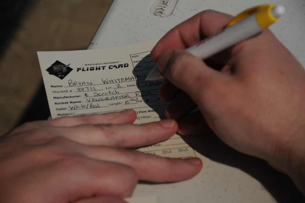
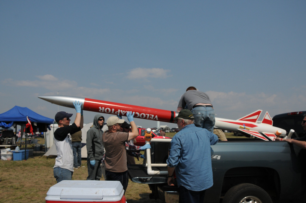
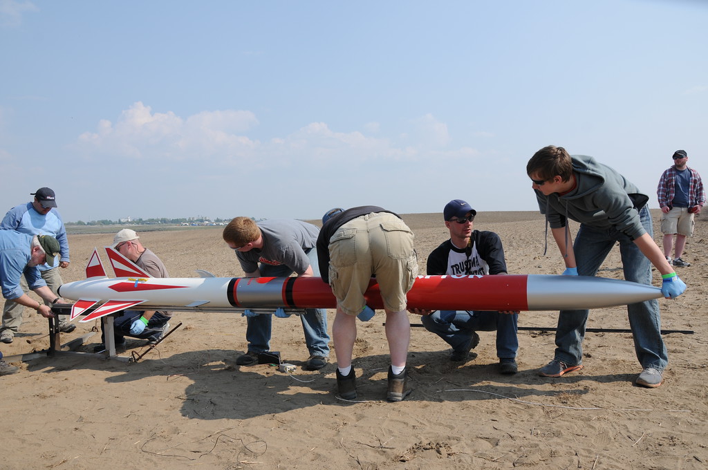
I certified L2 at FITS two years ago on my original Velociraptor. Last year I flew the Avenger. This year, I was hoping for L3 on the Velociraptor Rex.

First, though, there was the little detail of getting some other cert flights out of the way. We had four people looking for L1 from my camp. My brother and my daughter's boyfriend were each going for L1 while my son and daughter were both going for Junior L1. We decided to get those out of the way on Saturday so I could be free to work on my L3 on Sunday.

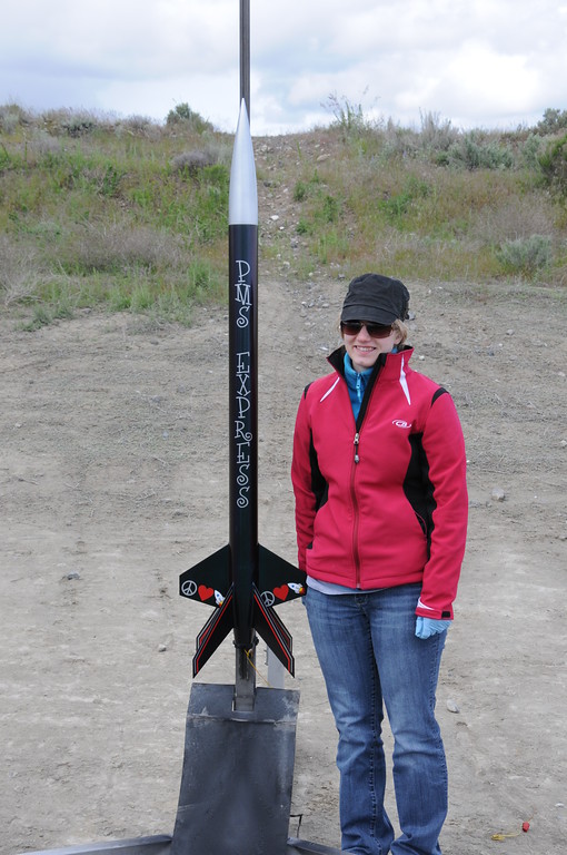
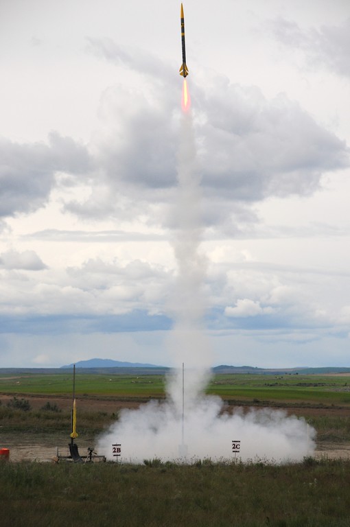
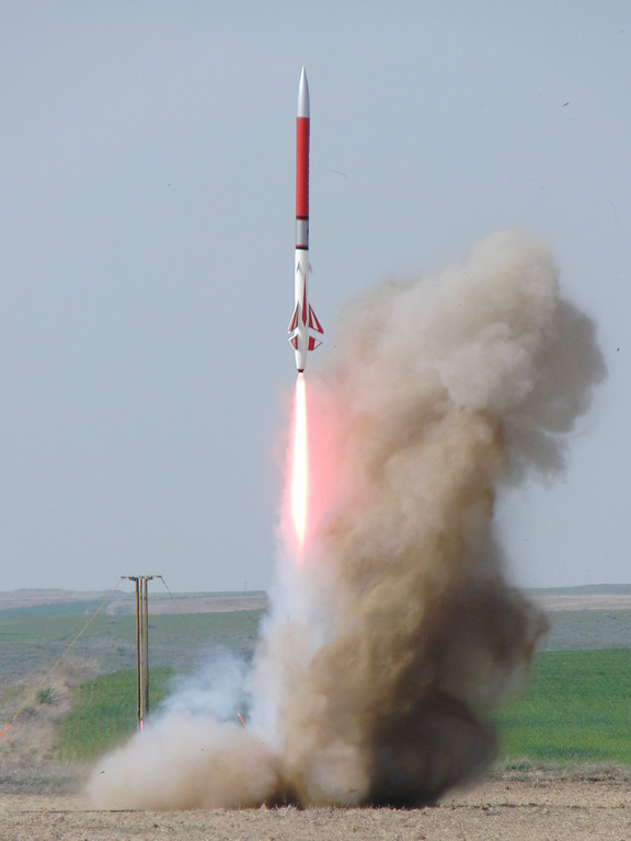
First up was my daughter, Jordan, with her Public Missiles Hydra named "PMS Express":tongue: Stickers were designed and cut by Jordan and I.
DSC5783-XL.jpg


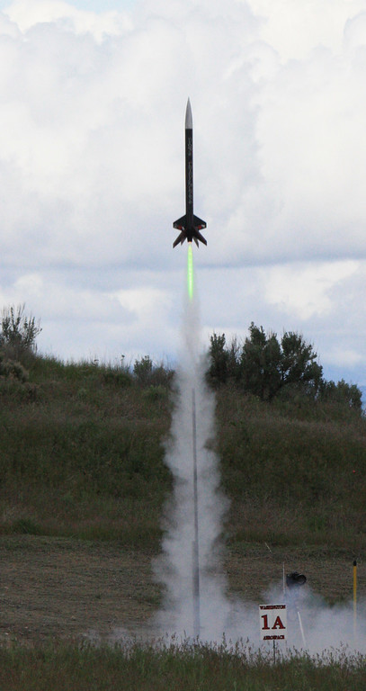
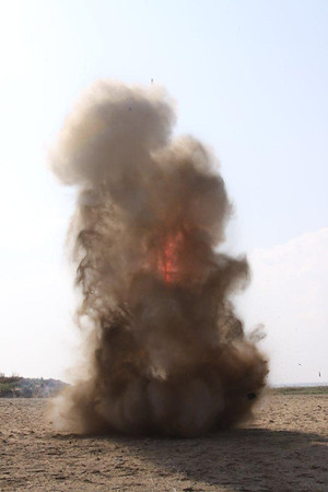
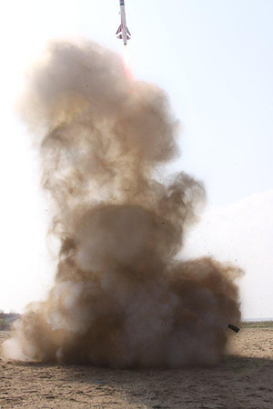
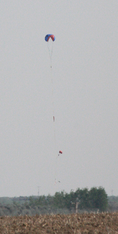
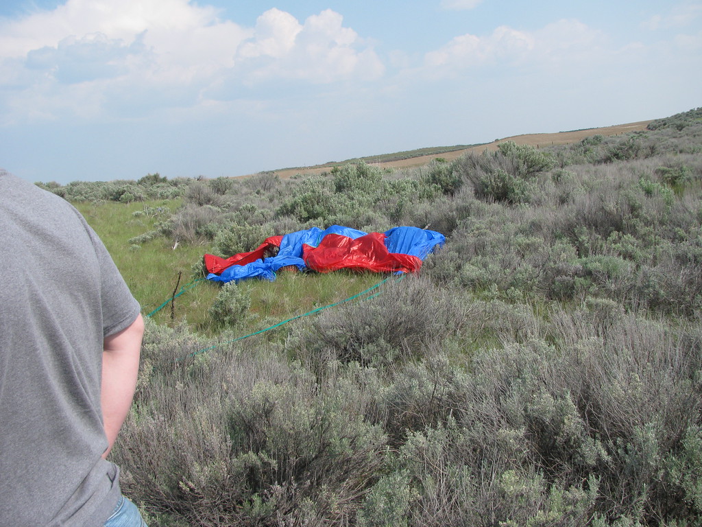
Her launch was on an Aerotech H250 Mojave Green motor. The up was great, but her parachute was partially fouled at ejection:eek:. There were a couple of tense moments, but then the parachute opened fully for a picture-perfect landing and a successful Junior L1 cert.:D 
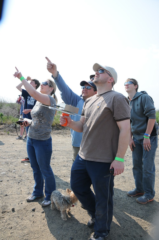
Waiting for her flight to go was honestly about the most nervous time of the whole weekend for me. I just about cried when her parachute opened fully and I gave her a hug.:blush:
PMS-Express-XL.jpg

Thanks to William Carpenter for the launch photo. I always am happy to see William when one of my rockets is about to launch. I know if I don't get the shot (or in this case, my wife doesn't), he'll be there to have my back. Thanks again, William!

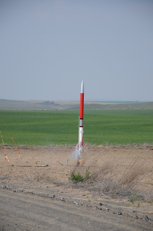
Next up was my brother, Dan. Two years ago he came to FITS as a spectator to see his first ever big rockets. Last year he came with an Estes Big Daddy (one of my first kits as a BAR as well). This year, he upped the ante A LOT with a beautifully built and finished Wildman Darkstar 4. We designed and cut the stickers for his impressive build as well.
DSC5828-XL.jpg


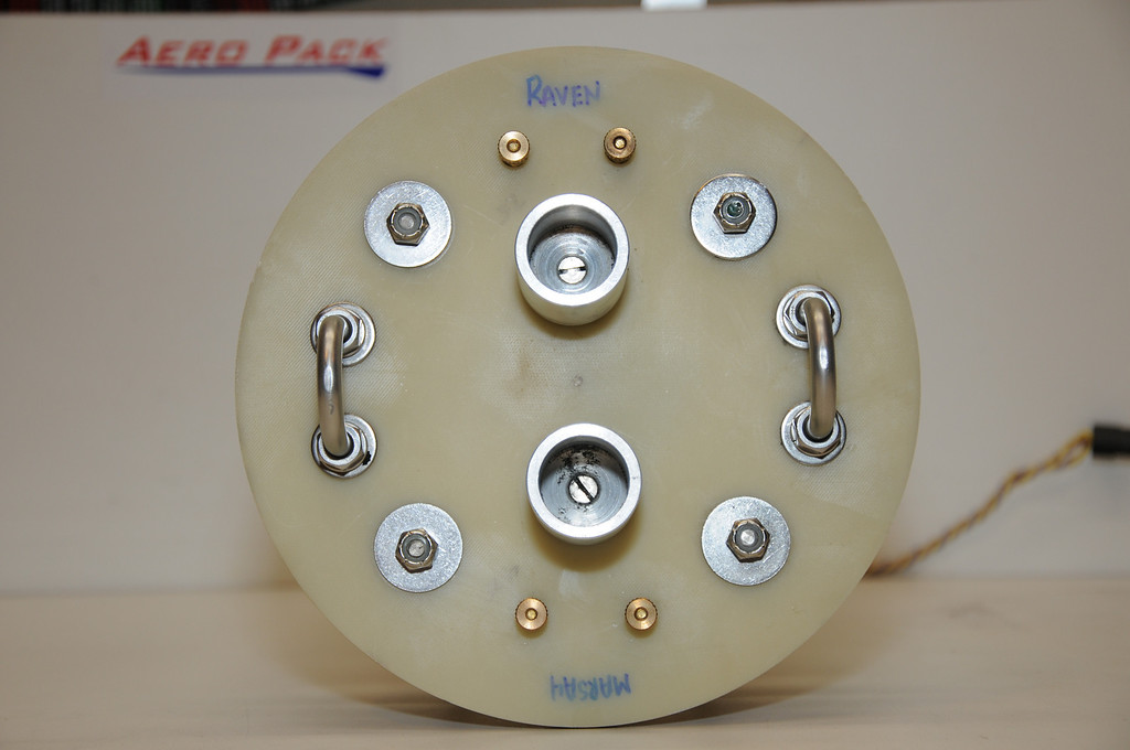
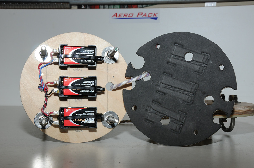
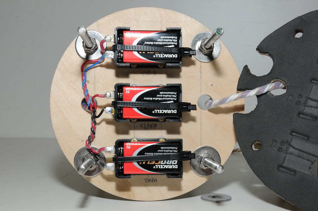
Dan flew his L1 cert attempt on an Aerotech I285 Redline. He had redundant electronics with a Raven and an RRC2 mini, choosing to go single deploy for this flight. Excellent boost, excellent apogee deployment (gotta love electronics) and easy recovery thirty feet or so from the pad. Two for two on the day:wink:.
DSC5852-XL.jpg


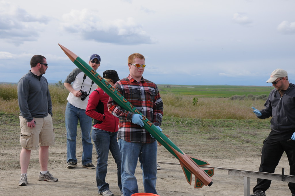
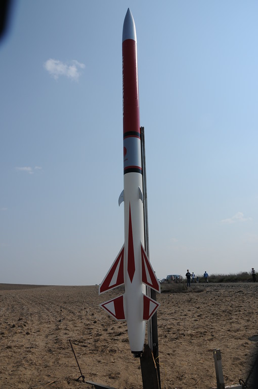
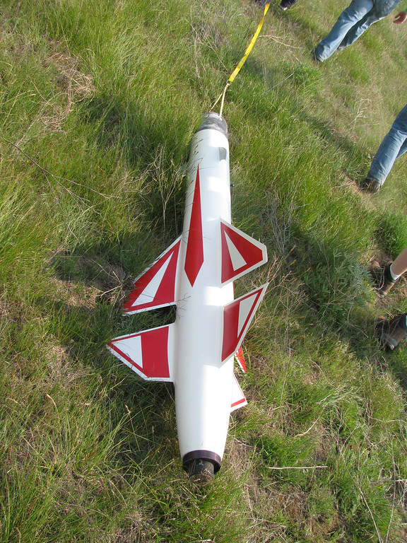
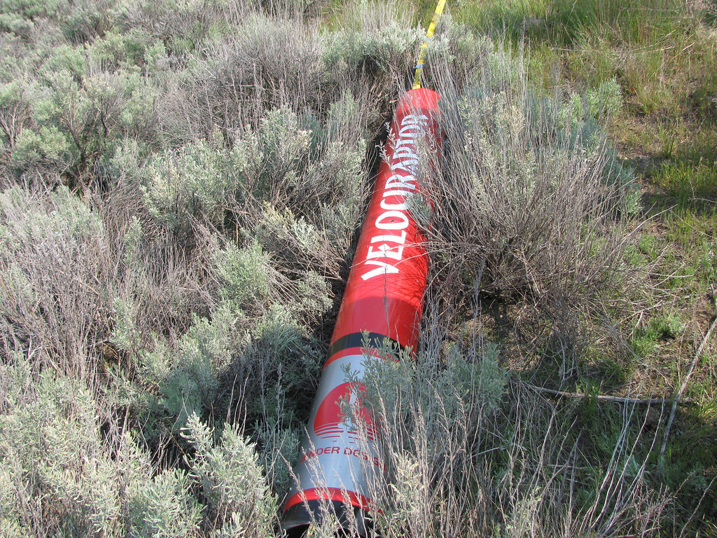
Then came Jordan's boyfriend, Dalton (they have consecutive NAR numbers -- isn't that just so adorable):smile:. Dalton and I have been working together on our projects since Christmas. He has been an eager learner and willing to take the extra steps to make his rocket great. He was rewarded with this beautiful Binder Design Raptor that he named the "Eradicator." We designed and cut the decals. He did the very detailed paint job, masking it off by eye.:eyepop: The paint is Spanish Montana copper and green. The copper turned out amazing.
DSC5865-XL.jpg


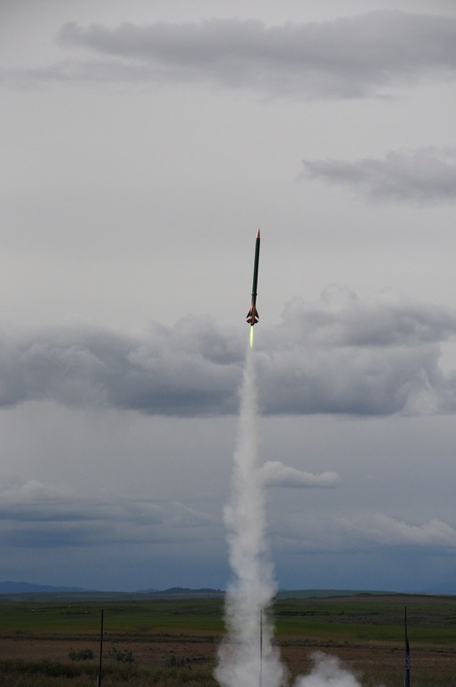
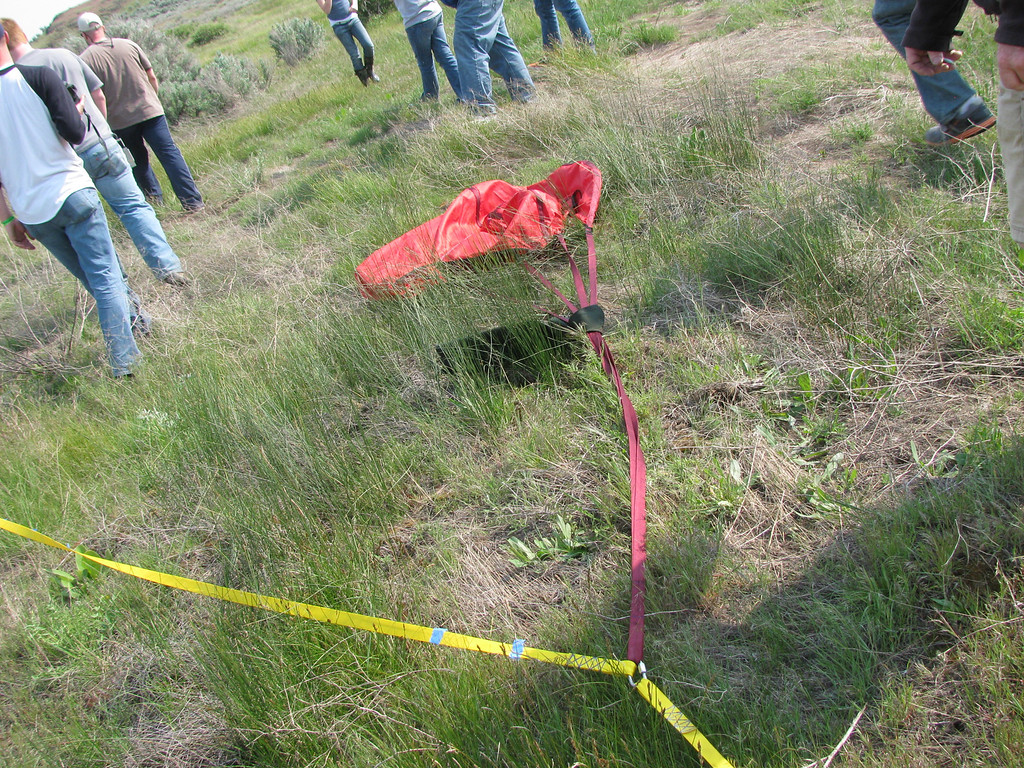
He chose to continue the green theme of his rocket by flying it on an I245 Mojave Green motor. He also flew with redundant electronics (his were a Raven and a PF MAWD) but chose to go with dual deployment just because he could.;) It ended up that he only got to about 700 feet on this little motor and his main charges were set for 800 and 700 feet respectively, so he ended up having all four charges go off and both parachutes deploy successfully at apogee. He beat Dan for closest to the pin. Three down, one to go.:cheers:
DSC5916-XL.jpg


Dalton was less than satisfied by his low altitude. Both his and Dan's rockets were really more designed for L2 attempts and using the lower impulse green motor looked cool but really didn't rip it off the pad like he wanted. I flew it the next day on a J415 White Lightning motor and he was much more satisfied with that result. I wanted to put a K550 in it, but there was too much wind.

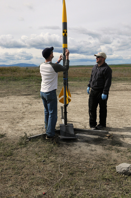
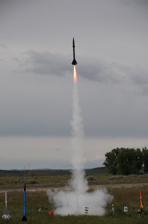
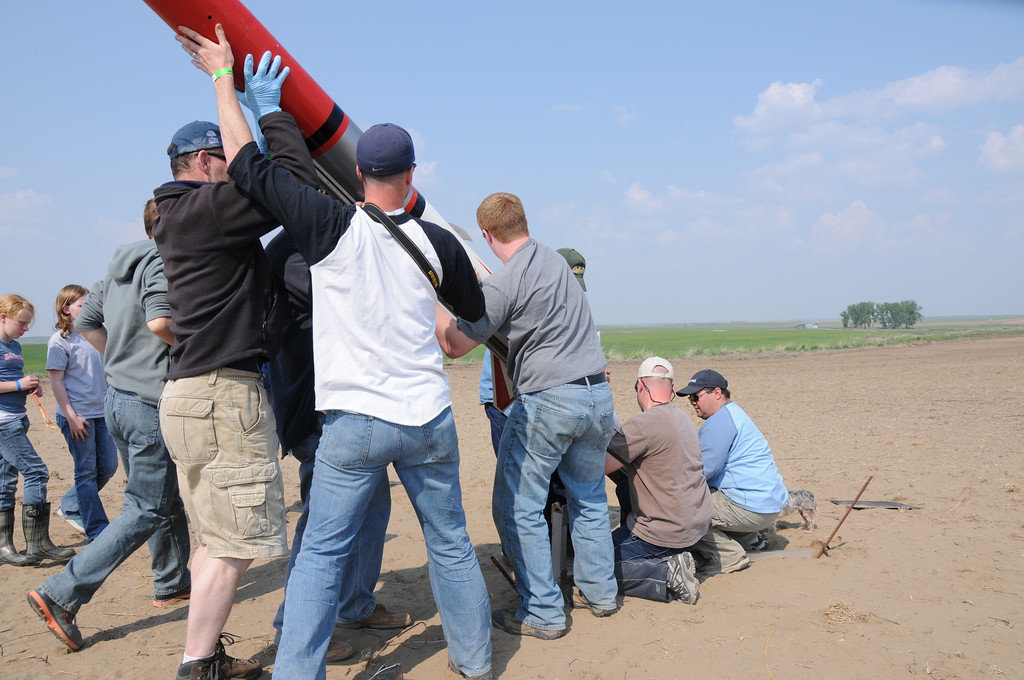
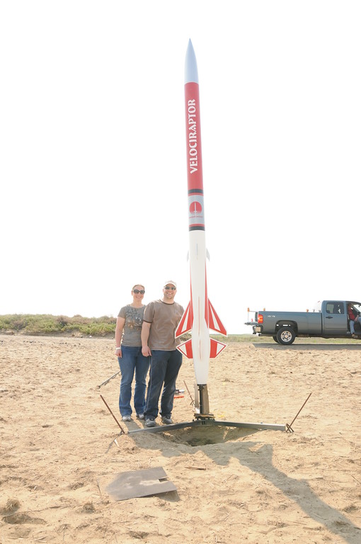
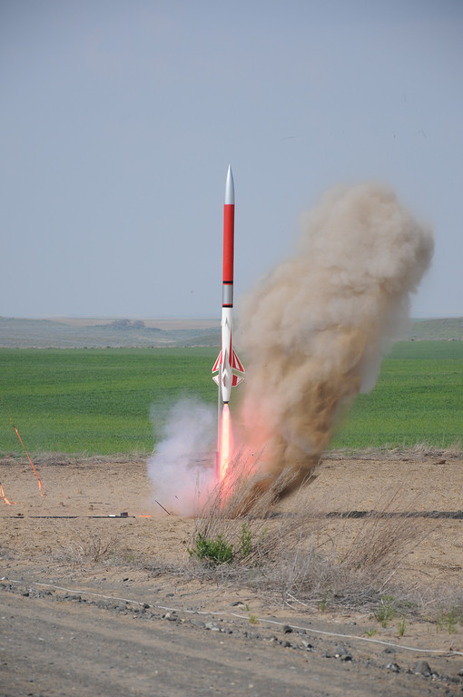
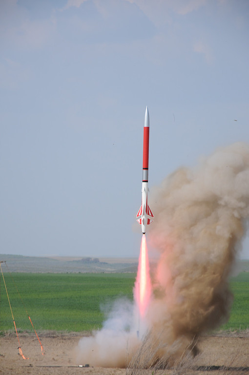
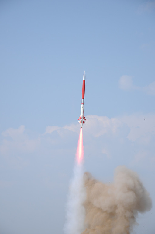
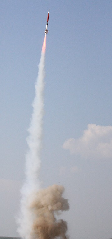
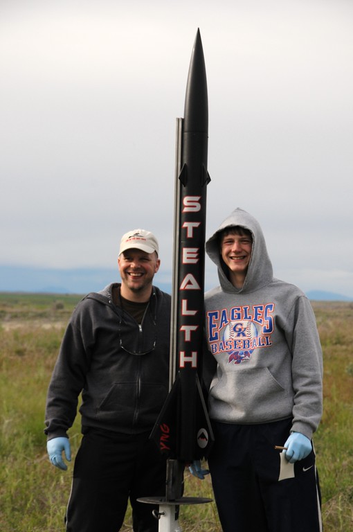
Finally, it was time for my son, Cody's flight. He build a Binder Design Stealth. Of course, we designed and cut the decals ourselves (gotta love having a decal cutter). The "YNG" on the fins was a shout-out to his older brother, Allen, who left for the Navy earlier in the week.:sigh: YNG was Allen's nickname when playing video games. I did not realize that the range would be closing that night at 6:00 and Dalton's flight and recovery took until about 5:40, so we had to take out Dalton's motor to use the forward and rear closures while the motor was still warm. I then rushed through building Cody's I366 Redline motor and we ran down to the RSO just in time to get on the last rack of the day. Here's Cody and I after throwing the thing on a pad.
DSC5993-XL.jpg


As we came back off the range, Dalton said to me, "I can't believe you built that motor in five minutes." For some reason, as I congratulated myself on getting the motor ready to fly, I realized that I forgot to put the stupid black powder in for the motor ejection :bangpan:. I sheepishly asked the LCO if I could pull the rocket for a last minute "adjustment," ran back to camp, and dumped the black powder in the all-too-clean ejection well. We then ran back out and with only moments to spare, put the rocket back on the pad. Liftoff was picture perfect with ejection of the parachute right at the top. This gave us a perfect four-for-four on certification flights in one day.:horse:
DSC6032-XL.jpg
 
After getting the four certs out of the way on Saturday, I was looking forward to my cert attempt in the late morning on Sunday. I woke to clear skies and calm winds at the motel 20 miles from the launch site. However, by the time we got on the plateau where the launch site is located, the wind had picked up substantially, gusting to about 25 mph. Although the weather was not anticipated to get much better, I went ahead and prepped in case things calmed a bit.

This shot shows the avionics bay on the left of the photo (wrapped in tape to tighten the fit in the airframe) attached to the drogue parachute bay. Attachment is with three 10-32 stainless screws.
DSC6157-XL.jpg


Here is a shot of the 6GXL CTI N4100 Red Lightning motor. The 3/8" all-thread is to aid in securing the motor by attaching it to the fincan bulkhead. This is a pretty heavy motor at more than thirty pounds.
DSC6161-XL.jpg


Here we are placing the motor in the fincan.
DSC6163-XL.jpg


The rocket is fully assembled and ready to go.
DSC6185-XL.jpg


Filling out the flight card.
DSC6197-XL.jpg
 
The wind calmed down nicely by the afternoon and we headed out to the away cell to get the Velociraptor on the pad. Thanks to Dale Woodford for the use of his truck. Would have been a long walk!
DSC6208-XL.jpg


The rest of the photos on this post are taken by Kent Newman, one of my L3CCs. Thanks for grabbing the camera from Shannon, Kent! She was freaked about trying to get shots.

Here we are unloading the rocket from the truck. We had enough hands that I just directed traffic.:)
DSC6224-XL.jpg


Loading on the 1515 rail.
DSC6233-XL.jpg


Standing it upright.
DSC6238-XL.jpg


The built-in standoff on the pad did not contact the back end of the boat tail, so we ended up propping the entire 120 pound rocket on a corner of a broken piece of 1x4. :eek:
DSC6246-XL.jpg


Here I am arming the electronics. I just poke a small dowel into one of the vent holes and push the three buttons inside. Works great.
DSC6248-XL.jpg


Here are a couple of cool shots taken by Kent looking up the launch rail.
DSC6253-XL.jpg

DSC6258-XL.jpg


My wife, Shannon, and I in the obligatory last pose before the button push. I was nervous enough that I forgot to give it a kiss before launch.
DSC6259-XL.jpg


The sun was not at a great angle to get the perfect shot, but this one is cool.
DSC6283-XL.jpg
 
After the flight was announced, I pushed the button and waited for the big motor to come up to pressure. These shots are all from Kent Newman.
DSC6286-XL.jpg


The motor blasted a fair amount of dirt out from under the pad.
DSC6293-XL.jpg


This flame has to be about 13 feet long or so!
DSC6294-XL.jpg


Beautiful liftoff shot by Kent.
DSC6295-XL.jpg


Here is a shot from a split-second later by William Carpenter.
IMG3311-XL.jpg


Here is another great liftoff shot, this one from Ken Tsai.
CIMG1928-XL.jpg


Here's a series of cool shots by Rick Clapp using his remote-activated camera.
IMG4684-M.jpg

IMG4685-M.jpg

IMG4686-M.jpg

IMG4687-M.jpg

IMG4688-M.jpg
 
Isn't that an awfully short rail for this size of rocket?

(Gorgeous liftoff shots though - I love the column of dust :D)
 
After the boost, I gave a loud whoop and promptly lost sight of the rocket. Fortunately, Denny Smith had it the whole time. He patiently pointed it out until first Shannon and then I finally caught sight of it.
DSC6329-XL.jpg


Here's a shot by William Carpenter showing the rocket under full parachute less than 3/4 mile from the pad. The main parachute is a 24 foot Rocketman. The drogue is an 8' Rocketman Mach II. They both look small from here!
IMG3319-XL.jpg


Travis Byrd took the next several shots. Here is the undamaged fin can. I'll have to replace the divot that the nozzle took:)
IMG3228-XL.jpg


This is the 8' Mach II Drogue. It is placed 1/3 of the distance from the fincan on the 60' length of 1" tubular nylon recovery harness.
IMG3229-XL.jpg


This is the body section containing the drogue and main parachute bay connected by the AV bay. I was surprised to hear the altimeter chirping out 12,800 feet. The Raven gave me 12,600 feet for an average of 12,700 feet. Not bad for a 120 pound rocket estimated by RockSim to hit 11,500 feet!
IMG3231-XL.jpg


Here's the nosecone with the BeeLine transmitter inside.
IMG3232-XL.jpg


This is what a 24 foot Rocketman chute looks like laid across the sage.
IMG3233-XL.jpg


This photo taken by my son, Cody, shows Dalton and I carrying the fincan back to the truck while Travis and Dan haul the airframe. It was awesome to have the support of all the ground crew to help with the heavy work!
DSC6361-XL.jpg


Headed back to camp. Thanks again to Dale for hauling us around in the truck.
DSC6365-XL.jpg


Final Stats:
Pad Weight: 121 pounds
Altitude: 12,700 feet AGL
Max Velocity: 664 mph

Thanks to all who helped with this successful certification. Thanks to Kent Newman and Jim Wilkerson for their guidance as my L3CCs, my wife, Shannon, for her patience and support, and the many folks who helped to make this cert happen. Thanks also to those of you who stuck with this thread to the end. I know there are lots of photos. I hope it didn't bog things down.

Regards,
Bryan
 
Isn't that an awfully short rail for this size of rocket?

(Gorgeous liftoff shots though - I love the column of dust :D)

The Rail is ten feet long. It looks really small, but I knew it was long enough to allow the rocket to come up to speed. According to RockSim, it reached minimal stable velocity at 52". There wasn't a hiccup as it left the rail.
 
That was a ten foot rail? Wow - it looks smaller than that. My L3 rocket was a lot smaller than yours though, so my perspective is a bit skewed. Looks like everything went perfectly for your cert - congrats :D

(When does it get the N5800? ;))
 
We've only got a 14K foot AGL waiver, so I think the N5800 will blow that up. If I can get it down to Nevada in October I'll fly it at BALLS. However, there is a member of our club who just happens to have a 72" long 98mm motor case that is well into the "O" impulse range and he may need someone who is dumb enough to have a 98mm motor mount that is over that length. I happen to know of such a rocket. So if he gets a motor done and if he wants to fly it in a rocket, I might hold onto the N5800 for a while and see what happens.
 
RocDoc

That is truly impressive............. Thank you for the inspiration !!

Any words of advice for me and my LVL1 attempt
(See the latest SA-14 Archer thread)

Paul
 
RocDoc

That is truly impressive............. Thank you for the inspiration !!

Any words of advice for me and my LVL1 attempt
(See the latest SA-14 Archer thread)

Paul

Hi Paul:

Thanks for the compliment. Was surprised to see this build tread come back up.

I started reading through the first thread, then it sorta got hijacked by the internal/external fillet debate. I've gone back and read them both and I'll post some thoughts. Not an expert by any stretch, but I'm happy to lend an opinion or two.

Bryan
 
You mentioned elsewhere that this has flown twice. Did you fly the EX O motor at BALLS?
 
You mentioned elsewhere that this has flown twice. Did you fly the EX O motor at BALLS?

No, I flew it at BALLS on the CTI N5800 to just under 15000 feet. The guy who had the O motor suffered a motor failure IIRC, so I'm kind of glad it wasn't in my rocket:roll:. Although as I've mentioned before, I generally only fly my rockets twice before retiring them, so it wouldn't have made much difference either way:)
 

Latest posts

Back
Top