rocdoc
Well-Known Member
- Joined
- Feb 22, 2009
- Messages
- 249
- Reaction score
- 0
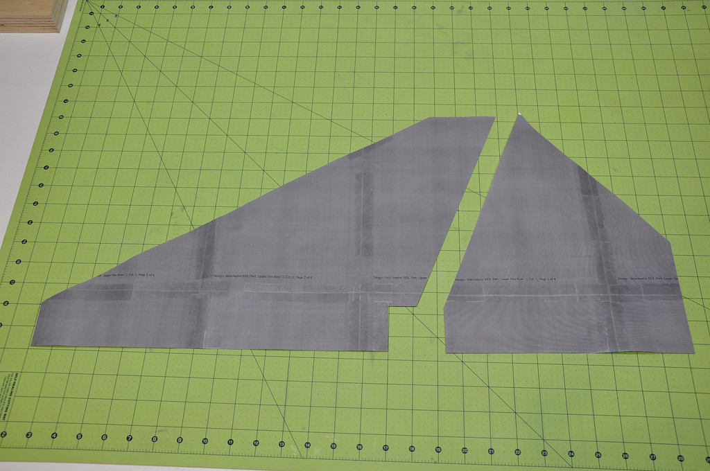
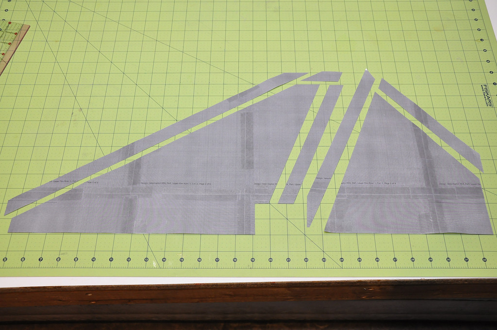
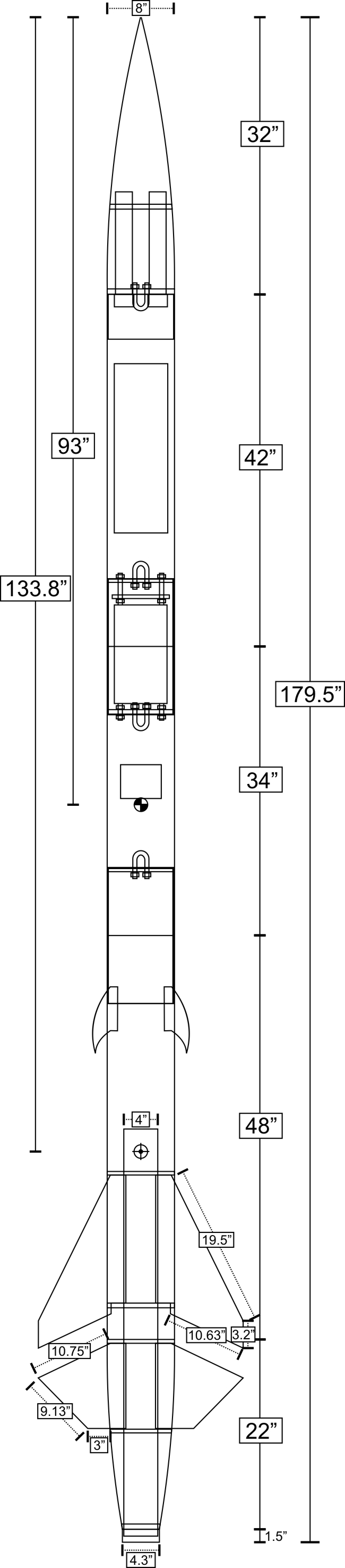
So Ive decided to go after my Level 3 certification. I certified Level 2 on a Binder Design Velociraptor. It is a relatively complex design by Mike Fisher with split fins and a set of upper talon fins. It is also a good flyer. I therefore decided to upscale it by a factor of 2 for my Level 3 project. The result is an 8 diameter, 15 foot tall, rocket with a 98mm motor mount able to accommodate any commercial 98mm motor. I plan to call it the Velociraptor REX. Here is a scale drawing:
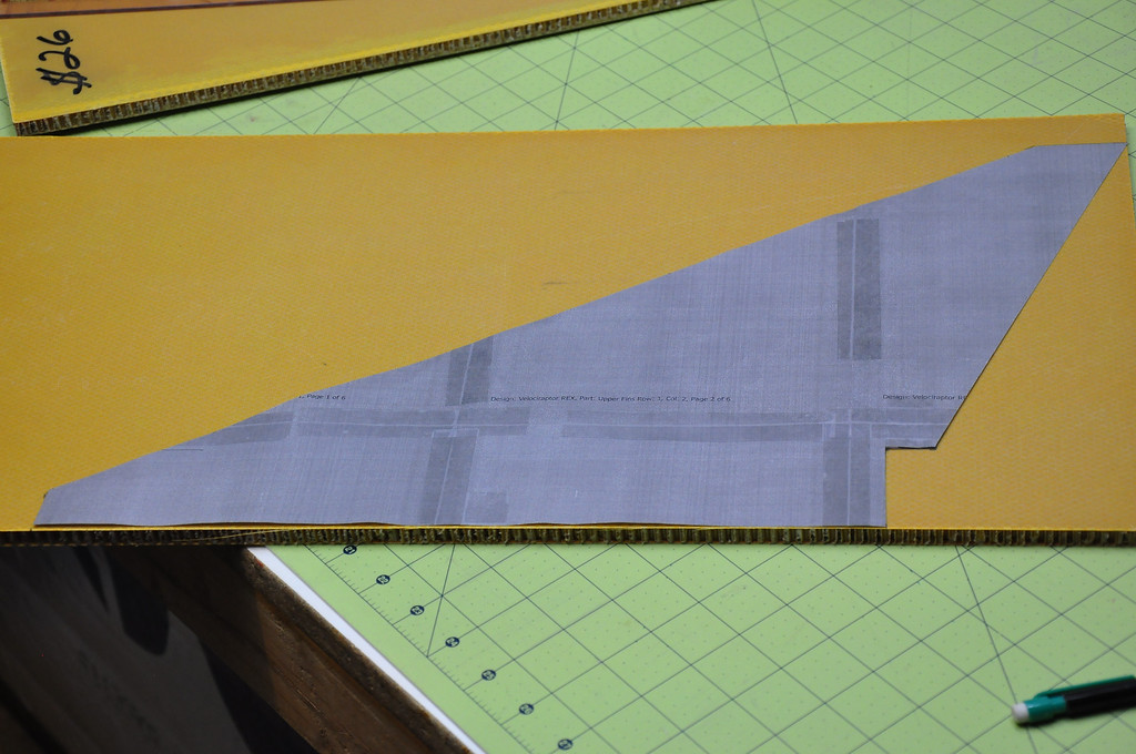
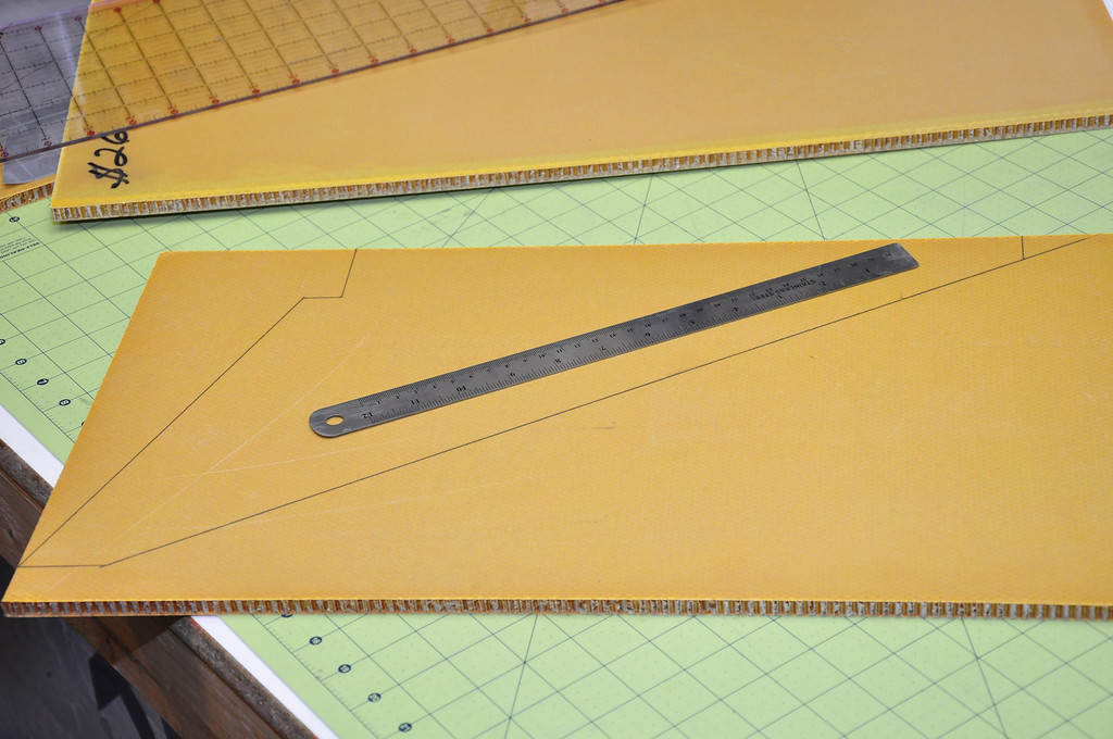
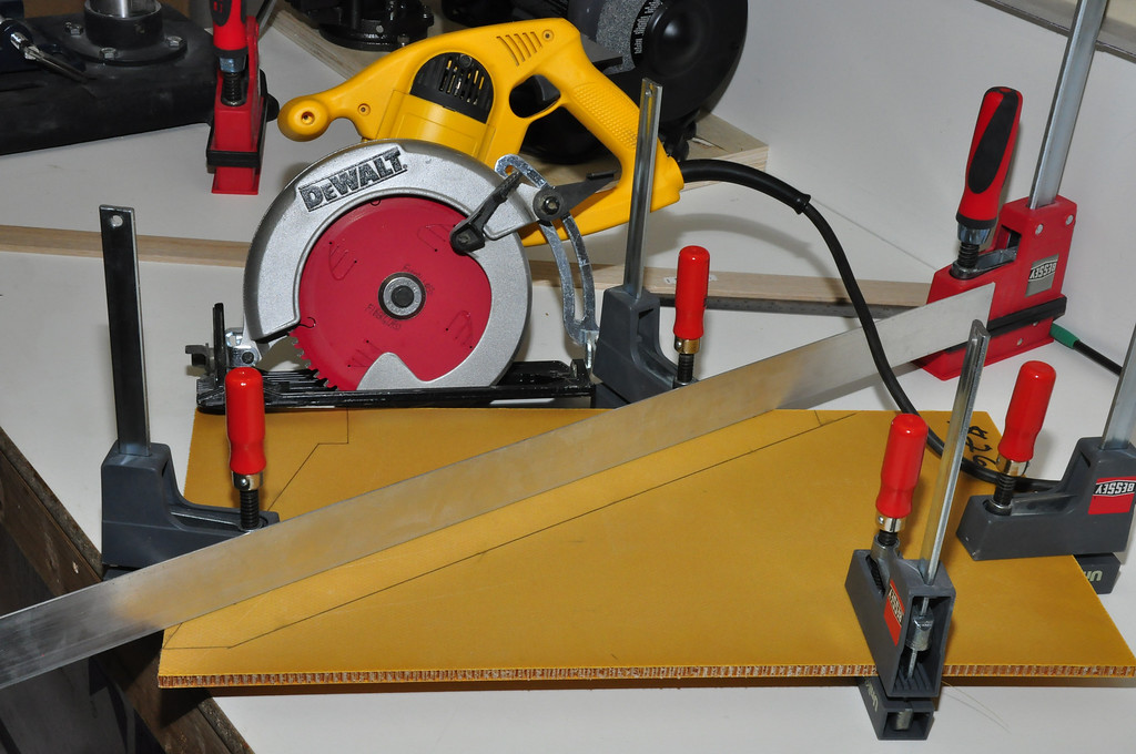
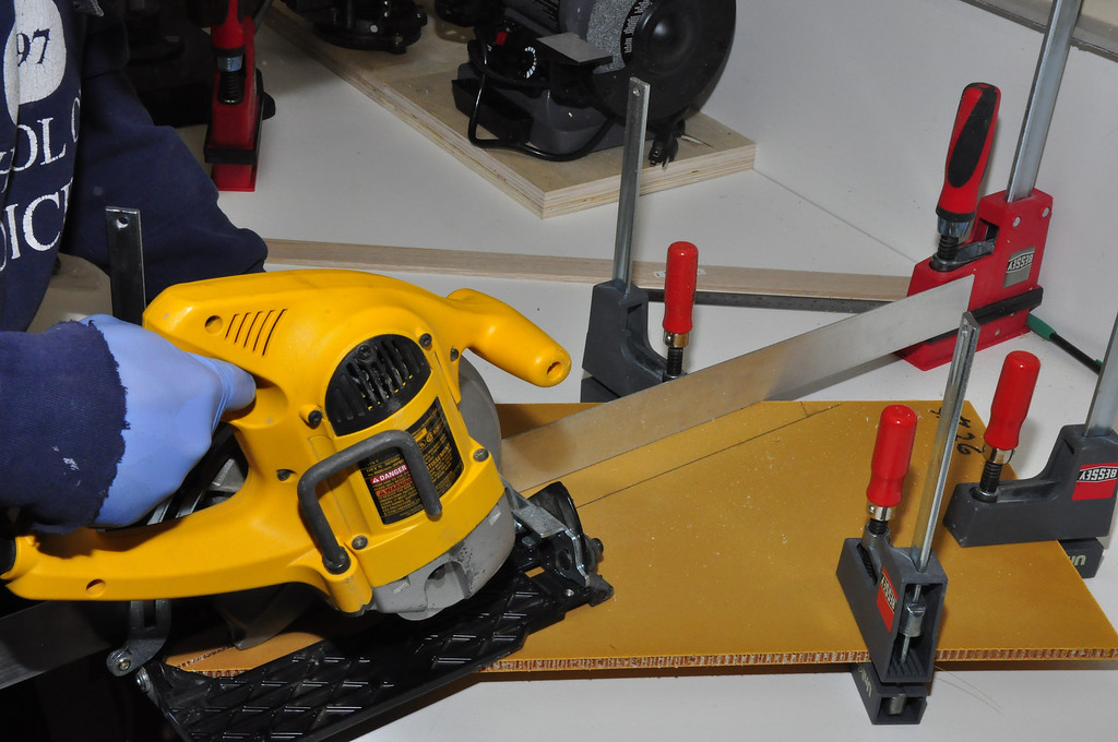
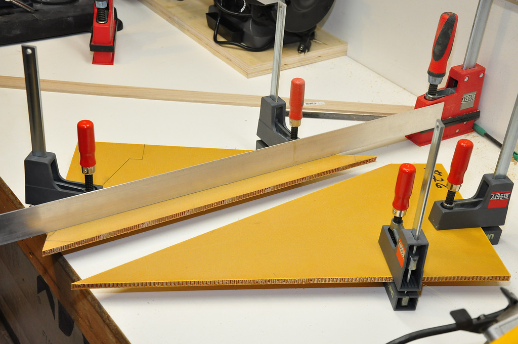
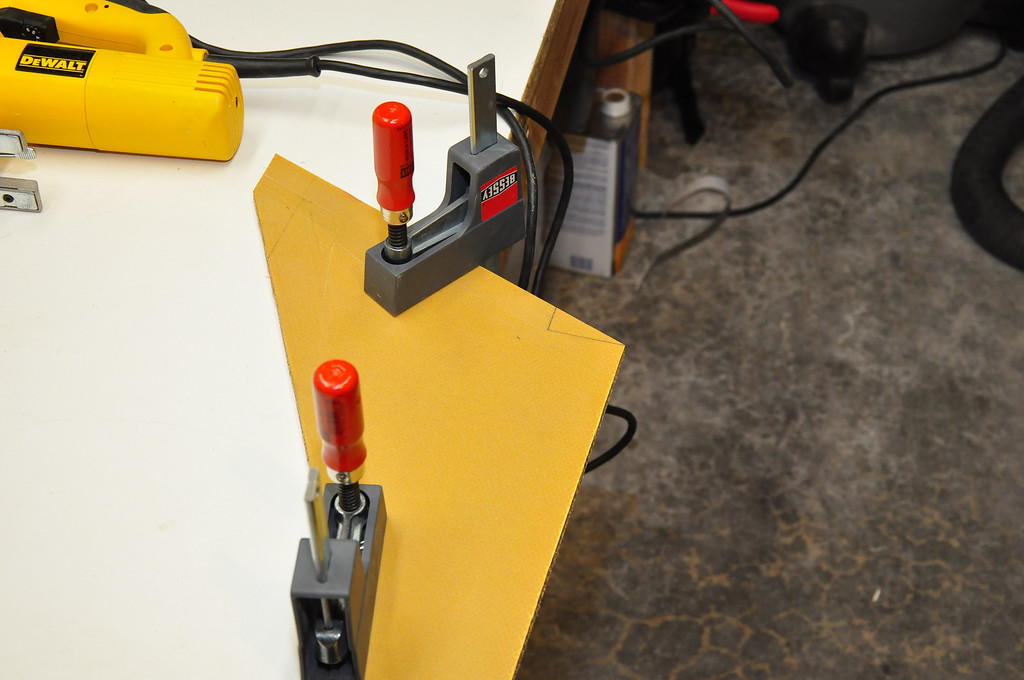
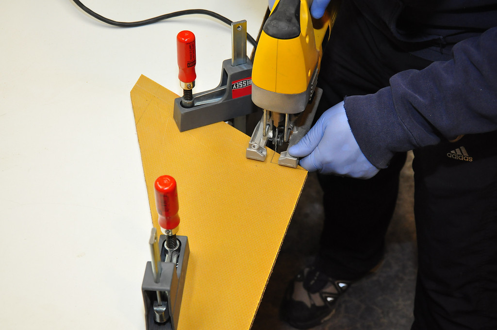
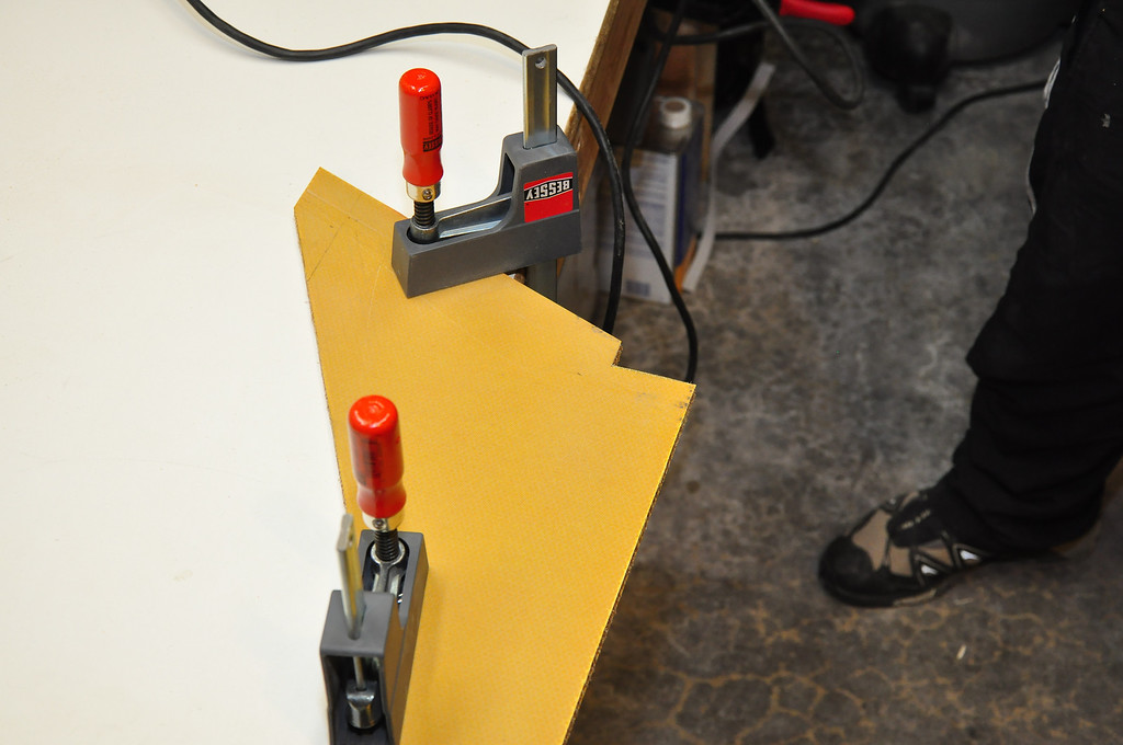
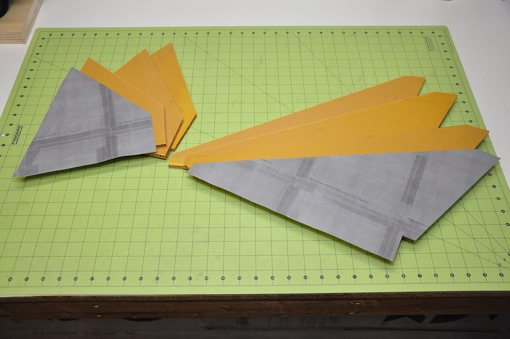
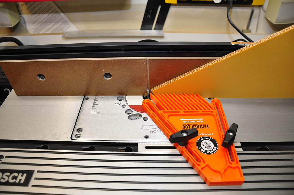
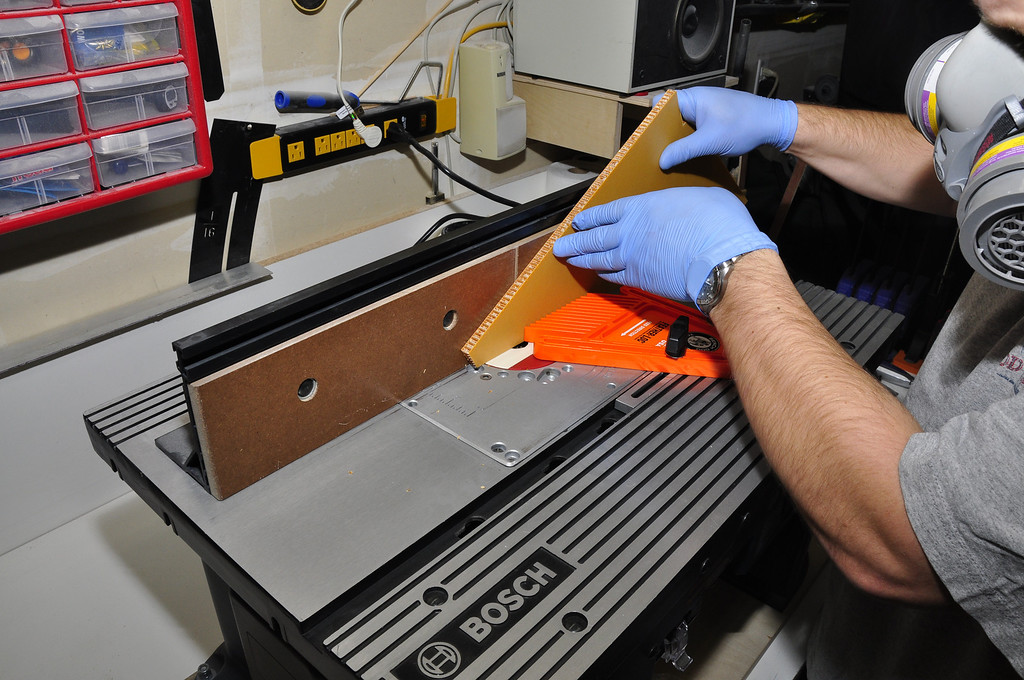
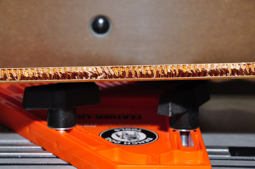
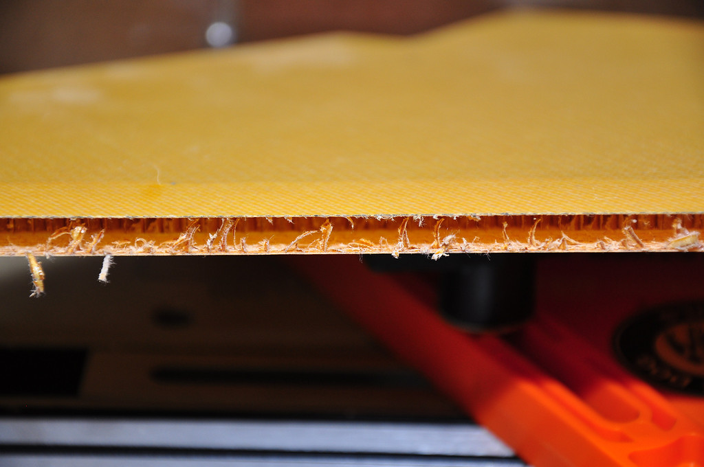
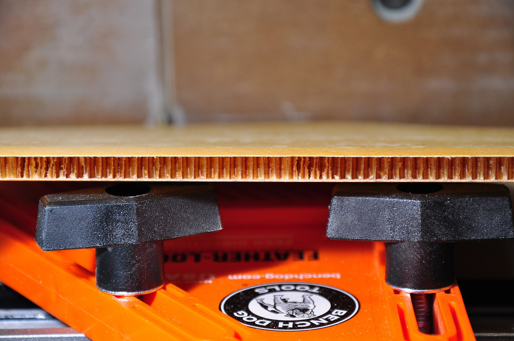
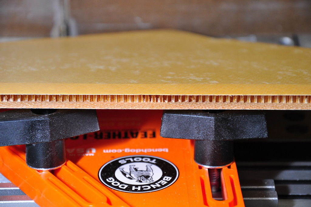
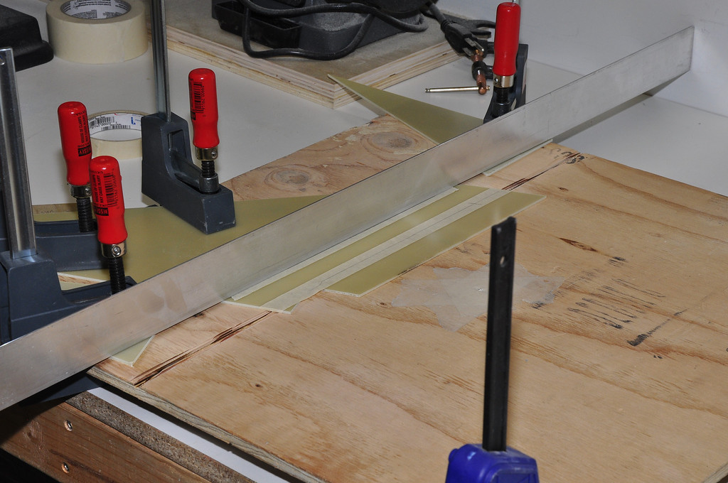
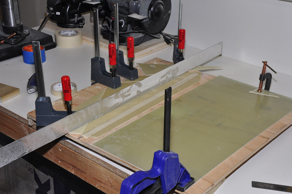
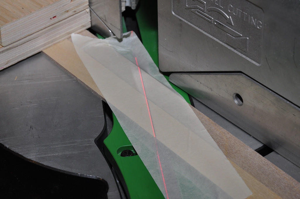
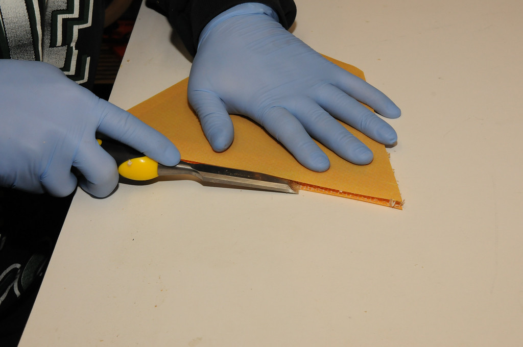
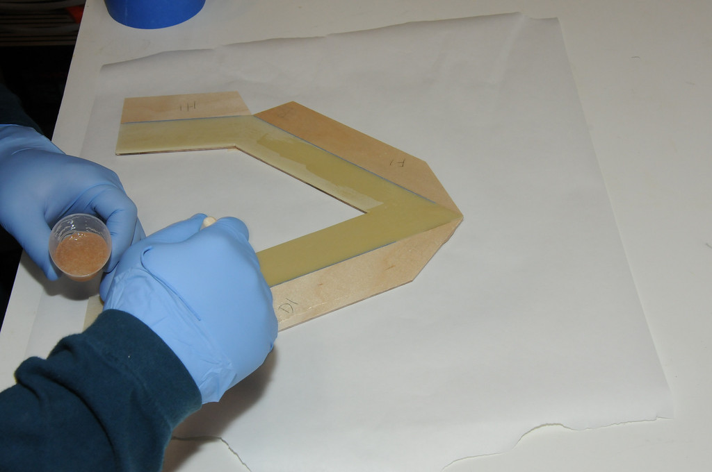
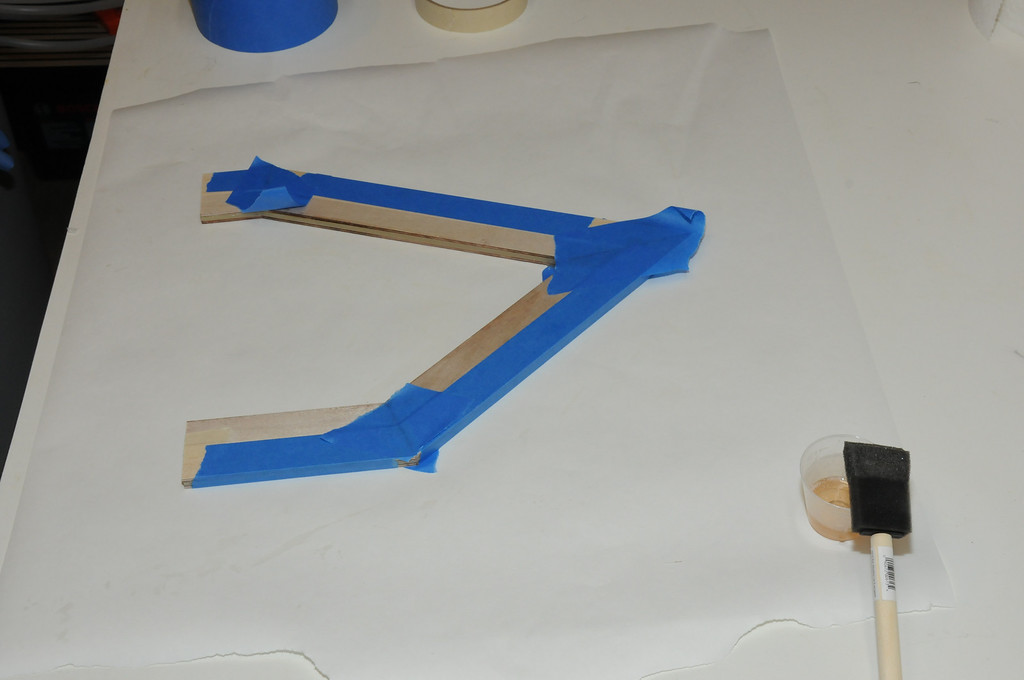
Airframe is all Performance Rocketry G12 filament wound Profusion tubing. Curtis Turner at Performance increased the strength of the Profusion tubing over regular G12 by adding additional wrap angles. It also is laid up using carbon-impregnated epoxy, resulting in a black color instead of the typical green. Nosecone and boat tail are Performance Rocketry 4:1 ogive fiberglass. To get the right thickness for the fins without adding excessive aft mass, I will use 3/8 Nomex honeycomb from Giant Leap Rocketry.
I have a propensity toward avoiding going small in my certification attempts. My Level 1 cert was a dual deploy Giant Leap Crossbow on an I284W. The Velociraptor was also dual deploy on a K550W. In keeping with the Go big or go home philosophy, this certification attempt will be on a CTI N4100 Red Lightning (74% N) motor. The red flame will also keep me from having another set of certification photos showing a White Lightning motor.
Electronics will consist of a MARSA4 with a PerfectFlite MAWD as backup. A Featherweight Raven will also be on board as a recording-only altimeter to provide a third data set. There will also be a GPS tracker and radio tracker in the nosecone.
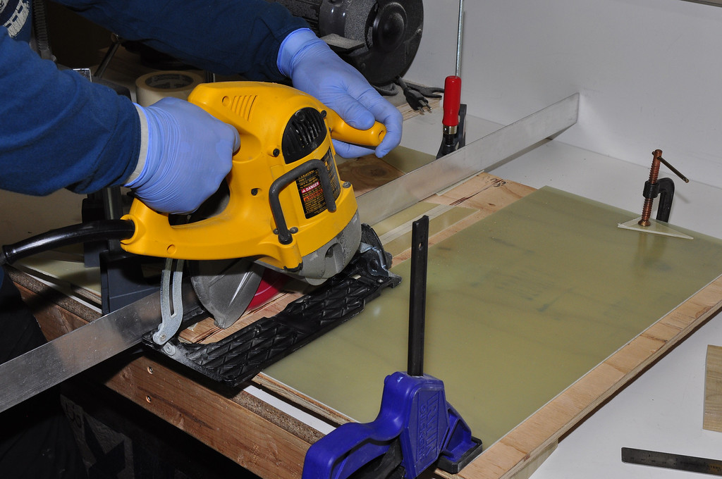
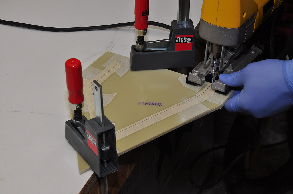
As was the case in my Avenger build thread, I plan to detail each step with high resolution photos. This is the only way that I have seen to adequately show what I am trying to show. I understand it increases loading times and may require scrolling on smaller screens, so I apologize in advance. I am a busy professional and father of three, so this will likely be an extended build thread. Please be patient and I will post as often as possible.
Finally, although I appreciate any insight into the build and my techniques, as is the case with all L3 builds, there are many correct techniques. Those shown here will likely raise some eyeballs. I welcome comments, but please understand that final build design and techniques are completely at my discretion under the guidance of my very experienced mentors, Kent Newman and Jim Wilkerson.
All that being said, lets get it on!
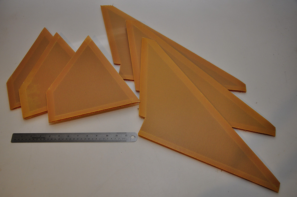
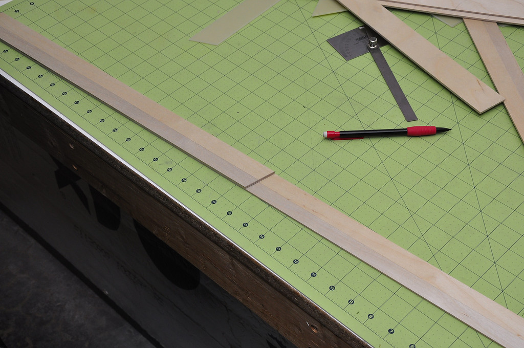
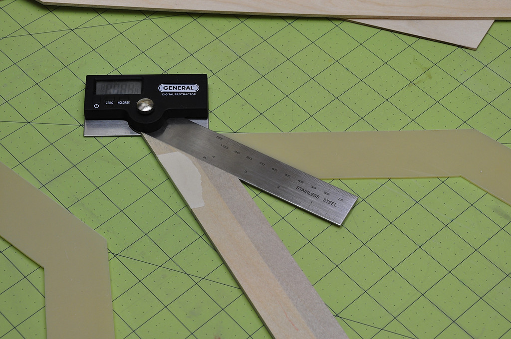
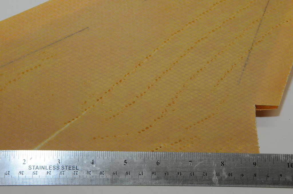
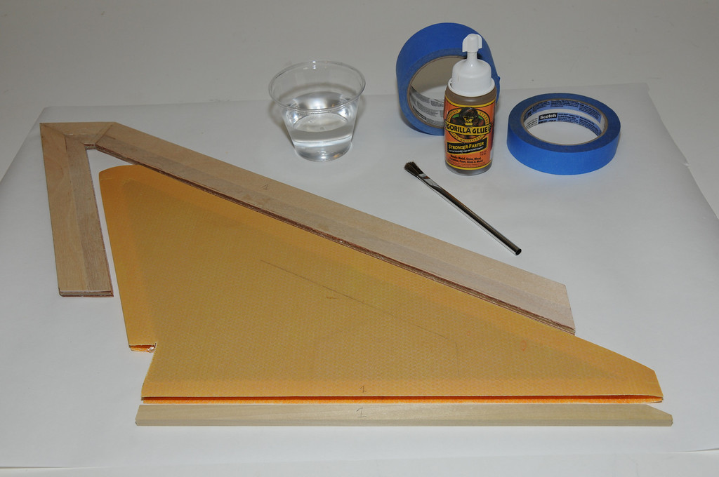
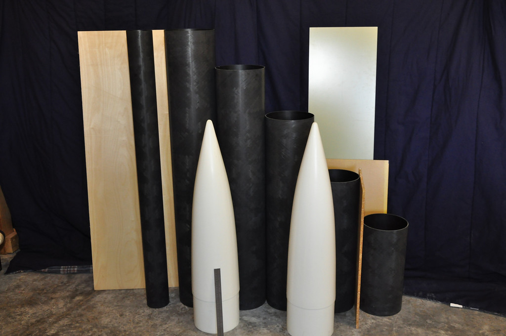
Here are a couple of photos of most of the raw materials needed. A 12 ruler is included for scale. This will end up being a pretty good sized project!:jaw:

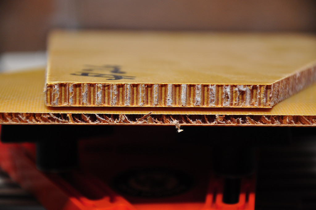
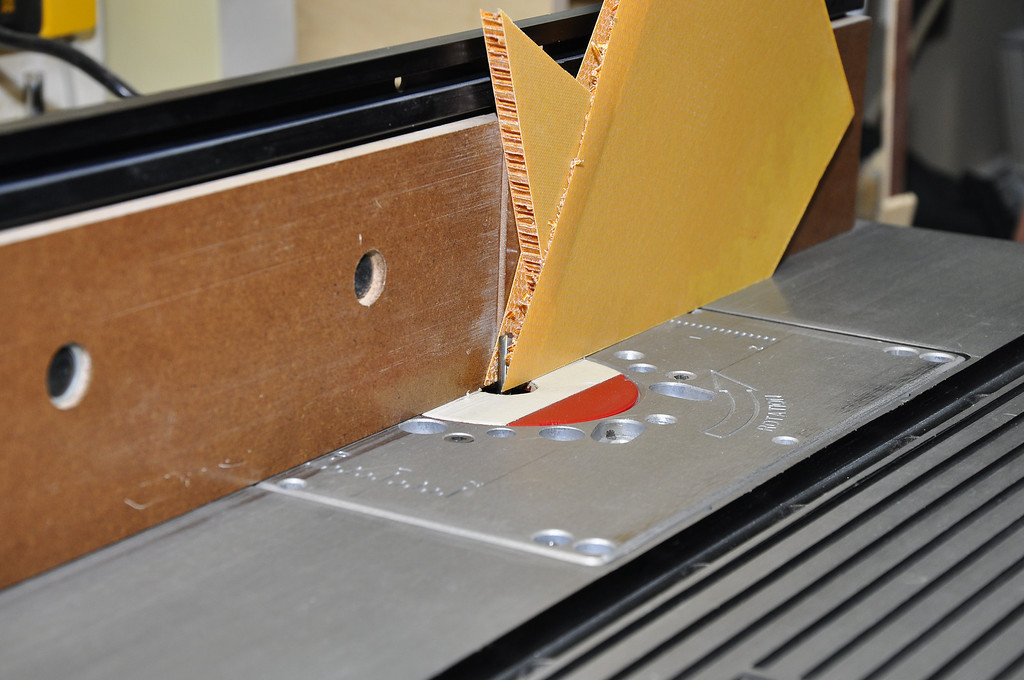
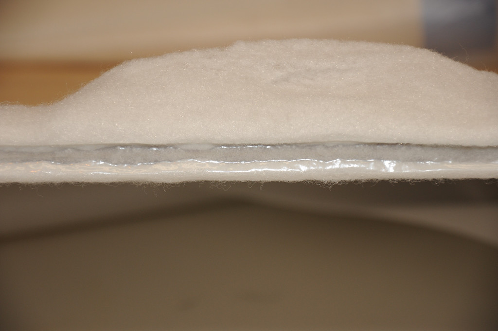
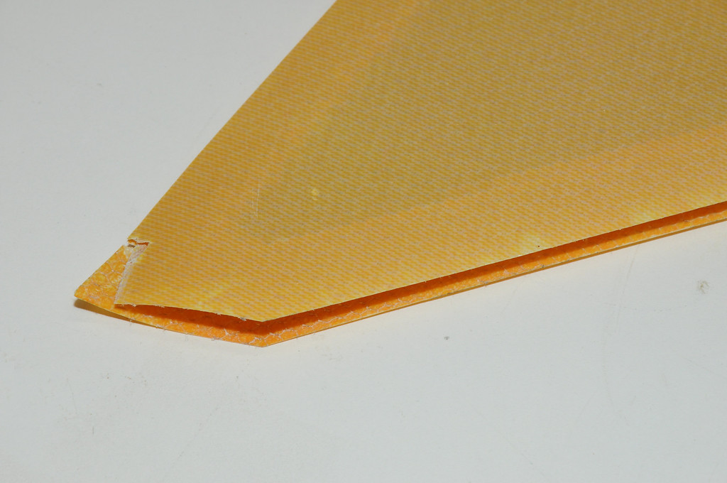
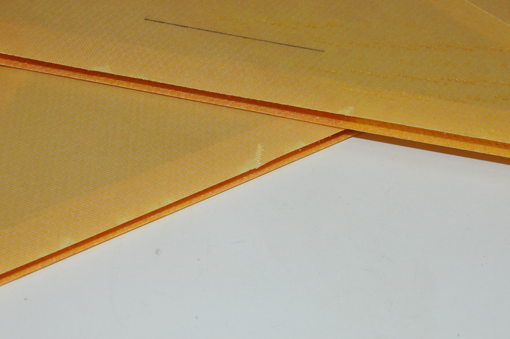
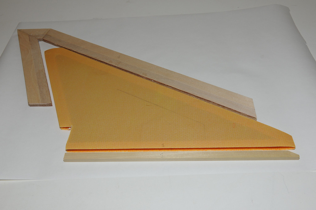
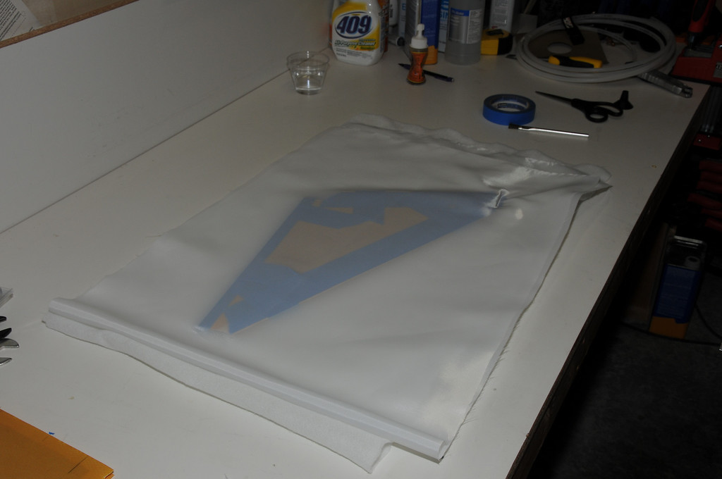
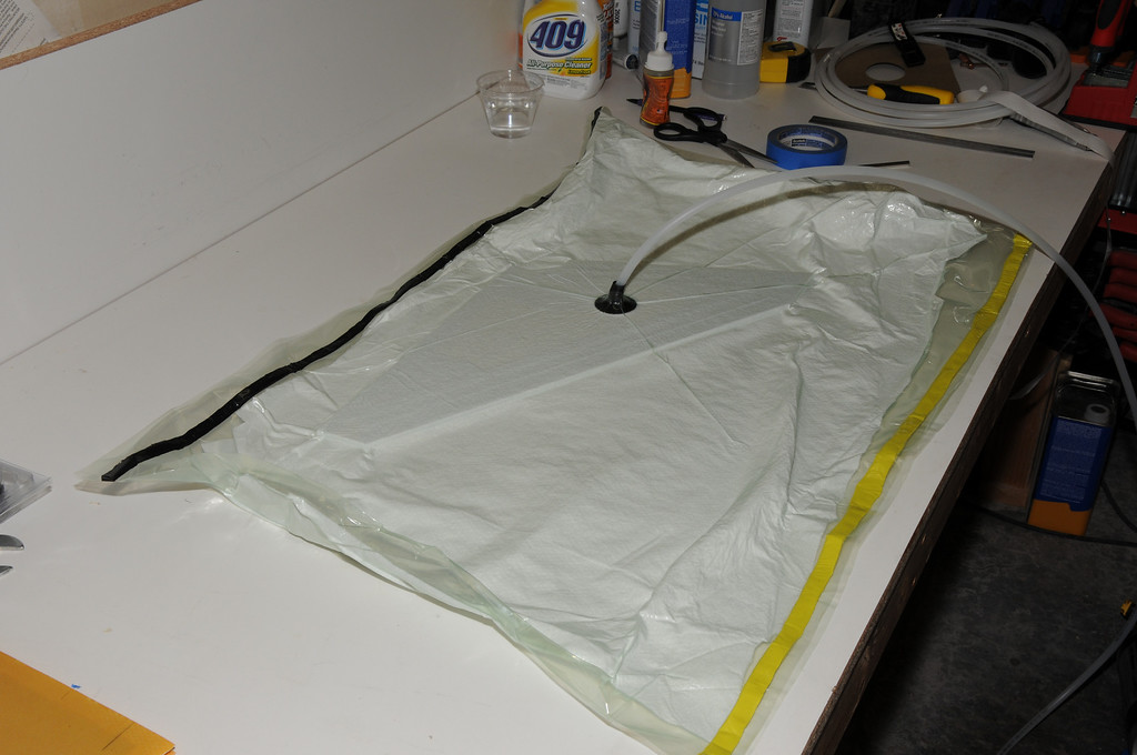
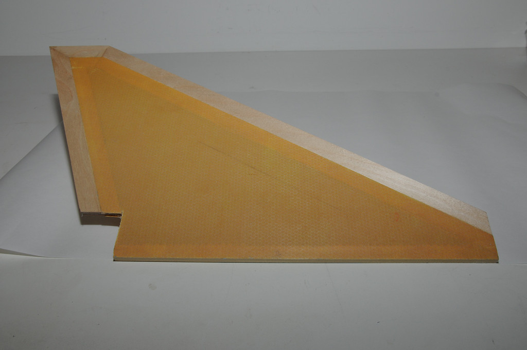
The tube on the left is the motor tube. It's 98mm diameter, 48" long. The N4100 will stick out another four inches or so from the forward end of the motor tube. The nosecones are 32" long without the shoulders. Two pieces of the 3/8" honeycomb fin stock are shown on the right side, one from the edge and one from the side.
Airframe is all Performance Rocketry G12 filament wound Profusion tubing. Curtis Turner at Performance increased the strength of the Profusion tubing over regular G12 by adding additional wrap angles. It also is laid up using carbon-impregnated epoxy, resulting in a black color instead of the typical green. Nosecone and boat tail are Performance Rocketry 4:1 ogive fiberglass. To get the right thickness for the fins without adding excessive aft mass, I will use 3/8 Nomex honeycomb from Giant Leap Rocketry.
I have a propensity toward avoiding going small in my certification attempts. My Level 1 cert was a dual deploy Giant Leap Crossbow on an I284W. The Velociraptor was also dual deploy on a K550W. In keeping with the Go big or go home philosophy, this certification attempt will be on a CTI N4100 Red Lightning (74% N) motor. The red flame will also keep me from having another set of certification photos showing a White Lightning motor.
Electronics will consist of a MARSA4 with a PerfectFlite MAWD as backup. A Featherweight Raven will also be on board as a recording-only altimeter to provide a third data set. There will also be a GPS tracker and radio tracker in the nosecone.
As was the case in my Avenger build thread, I plan to detail each step with high resolution photos. This is the only way that I have seen to adequately show what I am trying to show. I understand it increases loading times and may require scrolling on smaller screens, so I apologize in advance. I am a busy professional and father of three, so this will likely be an extended build thread. Please be patient and I will post as often as possible.
Finally, although I appreciate any insight into the build and my techniques, as is the case with all L3 builds, there are many correct techniques. Those shown here will likely raise some eyeballs. I welcome comments, but please understand that final build design and techniques are completely at my discretion under the guidance of my very experienced mentors, Kent Newman and Jim Wilkerson.
All that being said, lets get it on!
Here are a couple of photos of most of the raw materials needed. A 12 ruler is included for scale. This will end up being a pretty good sized project!:jaw:
The tube on the left is the motor tube. It's 98mm diameter, 48" long. The N4100 will stick out another four inches or so from the forward end of the motor tube.
The nosecones are 32" long without the shoulders. Two pieces of the 3/8" honeycomb fin stock are shown on the right side, one from the edge and one from the side.