My L3 build - Performance Rocketry Competitor 6

The Rocketry Forum

Help Support The Rocketry Forum:

This site may earn a commission from merchant affiliate links, including eBay, Amazon, and others.
You could probably use any number of graphics programs, but I use Corel Draw X4 from the Corel Graphics Suite. I chose this program because I have been using it in my career for the last 15 years or so! It scales very accurately, so I can draw something to exact specifications, and hit print. The printout will be exactly to scale. It is precise to 0.001".

Cris
 
What is your thought on this program? punch ViaCad 2d/3d i had seen what you have done but WOW corel draw $$380.00.
 
I watched the demos and the program looks very nice. I wouldnt recommend you spend almost $400 on Corel, as most of the software's power is in graphic design and photo editing, rather than engineering or CAD. I just use it because I already own it, and am very familiar with it.

I saw that you can download a trial version of ViaCad. Perhaps you could try that and see how it works for you =) If you do, please let me know what you think!

Cris
 
Oops, I have been so involved in this avionics bay, that I forgot... I never poured my fin fillets!

As usual, I used my large tongue depressor (thats a large depressor, not a depressor for large tongues) to guage the size of the fillets. Then, I masked off the areas just outside where the fillets will be:

L3&


Next, I made a mixture of US Composites 1:1 thick epoxy and microbaloons (consistency of cake icing) and applied it to the fillet area. Then, using my alcohol-soaked tongue depressor, I shaped the fillets. The alcohol keeps the epoxy mixture from sticking to the depressor...

92pouringandshapingfillets.jpg


Then, I dipped my finger in alcohol and perfected the leading and trailing edges of the fillets. Well, I got em close enough! I will sand them to their final shape when all the fillets are poured and cured. While the epoxy was still setting up, I neatly removed the masking tape:

93removingmaskingtape.jpg


Now to do this two more times, then back to the avionics bay!
 
Wow, its been over a month since I last worked on my Level 3 build! Seems like even longer =(

I just made a big career change, and the adjustment to the new job was occupying all of my free time. But I love the new job, and I am finally "settled in" and ready to get back to my hobby!

So getting back to those fillets...

The epoxy has had about 5 weeks to cure, so I figured they were ready to sand. I fashioned a sanding jig by taking an unused LOC/Precision launch lug, and wrapping some adhesive-backed sandpaper around it:

94makingsandingjig.jpg


95makingsandingjig.jpg


Then I used this jig to sand the fillets to a smooth, primer-ready finish:

96sandingfillets.jpg


97finishedfillets.jpg


The aft centering ring was still raw, unsealed plywood. So using a disposable brush, I applied a thin coat of US Composites Thin epoxy:

98sealingrearcenteringring.jpg


Now, I have to get off this computer and install the Aeropack motor retainer!
 
Now, I have to get off this computer and install the Aeropack motor retainer!

Not much you can do now, but from watching others and my dad its easier to put the inserts and drill on the drill press to keep things linned up before the aft CR is inserted. Just passing on my observations, enjoy or throw out ;)

Ben
 
Fortunately for me, I'm a professional hole-driller, so I'm pretty good free-hand! Hehe

Cris
 
Choosy rocketeers choose Jif!

99markingretainermountingholes.jpg


A jar of Jif peanut butter fit perfectly snug into the MMT, so I used it to keep the Aeropack retainer aligned, while I marked the hole locations with a scratch awl.

Then I drilled the holes out with a 15/64 bit...

100drillingretainermountingholes.jpg


Then installed the threaded inserts with a hex wrench...

101installingthreadedinserts.jpg


And a few drops of CA around each insert assure that they dont spin later on, when I tighten the cap screws:

102applyingcatoinserts.jpg


Last, I temporarily attached the motor retainer to make sure everything aligned correctly. It passed the "Jif test", so its good to go!

103installedmotorretainer.jpg
 
70roughingupinsideofboosterairframe.jpg


Brushed on a LOT of 1:1 slow epoxy (being VERY careful of my Fiance's chairs - Did this while she was sleeping!!):

71brushingepoxyinsideboosterairfram.jpg


Dude you have huge Balls to do that on your fiance's chair. Sweet build btw. Minimal equitment yet definitely one of the cleanest builds I have seen. Good work and good luck with the flights when it comes around.
 
Really awesome build! looks like you're close to being ready for paint too, have you given any thought to the paint scheme yet? - when are you planning to fly it?
I just saw the CAD plans you did to kick off this thread. all i can say is WOW.
Very professional, from the very the start. Which CAD package do you use? I'm just getting started on my L3 plan/project- do you have any advise on doing the CAD DWG's ?

Great job, hope to see it fly!
 
Thanks =)

The booster is ready for primer, but I still have to work on the nose, and the avionics bay first.

I'm not sure when I'll be ready to fly... hopefully our August launch. But money is tight, and I still need about $1200 between motor and casing, plus the parachutes. Ack!

Haven't really thought much about the paint scheme. My original drawings had it looking like a military missle, in olive drab with red & silver metallic accents. Sort of a "scale" paint scheme, if there is such a thing for a sport rocket!

Otherwise I may go crazy and do flames or somemthing wild and bright.

I kind of like the military look myself. Ill have to post the "CAD" drawings sometime.

Speaking of CAD, I didnt use a true CAD system to make the drawings. Rather, I used Corel Draw X4. Its just a 2D drawing program. I have been using this program for work for about 10 years, so I stuck with what I knew.

Would have been nice to have 3D renderings, but the 2D will do for my needs I guess.

Thanks again for the kind words,
Cris
 
Wow, has it been a month already?! The booster is now complete, so I went back to working on the avionics bay. I spent a lot of time re-thinking the design, and soaking in the advice I received on this and my other thread about the recovery system. In the end, I decided to add a PerfectFlite timer as a backup to the two altimeters, and to reduce the number of switches from 6 down to 3. I will have to go back to the beinning of this thread and update the CAD images of my design.

A couple months ago, I had completed the basic structure of the avionics bay, and set it aside in order to complete the booster section. Here's where I left off...

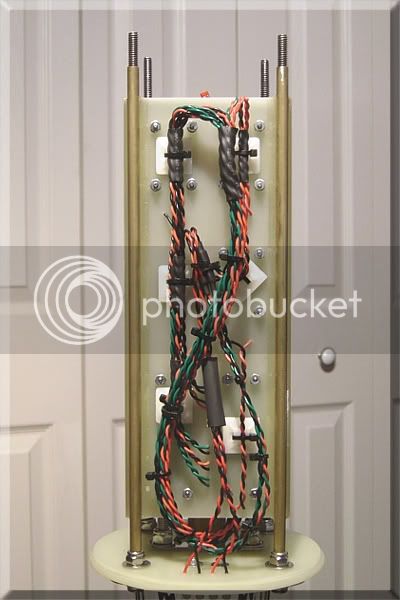
The completed endcaps, with Rouse-Tech CO2 hardware installed, and the electronics sled installed...

81avionicsbayassembled.jpg


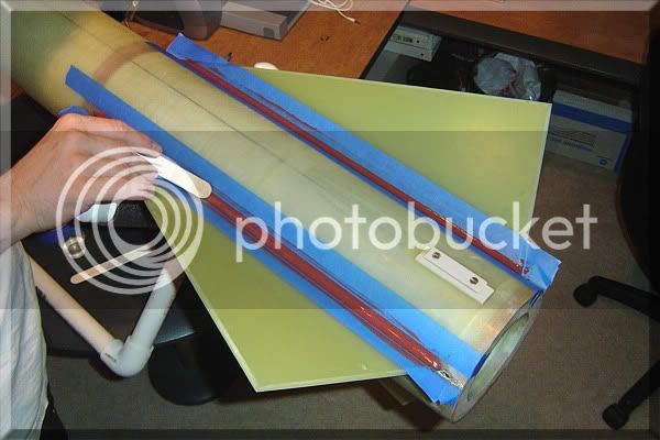
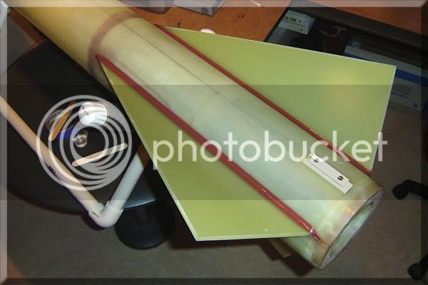
And the completed exterior of the avionics bay...

90jbweldingnutsinplace.jpg


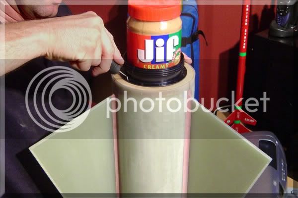
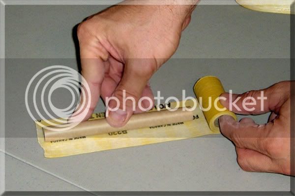
In order to attach terminal blocks for the e-match leads, I drilled mounting holes in each endcap, as well as 1/16" holes for the connector leads:

104drillingbarrierstripmountinghole.jpg


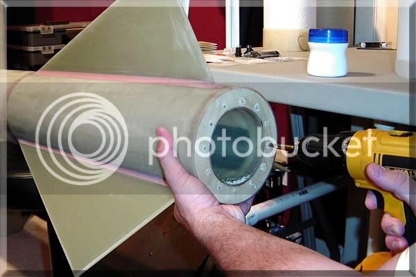
I attached each terminal block using two stainless steel machine screws, washers, and some threadlock:

105attachingbarrierstrip.jpg


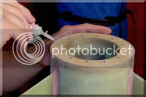
After attaching the connector leads, I put a drop of CA in each hole to ensure the leads don't get pulled out of the terminal block:

106installingmainchargeconnectorlea.jpg


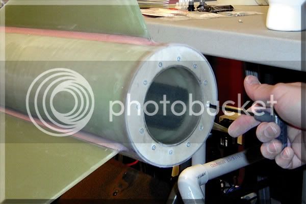
One of the completed endcaps:

107completedavionicsbayendcap.jpg


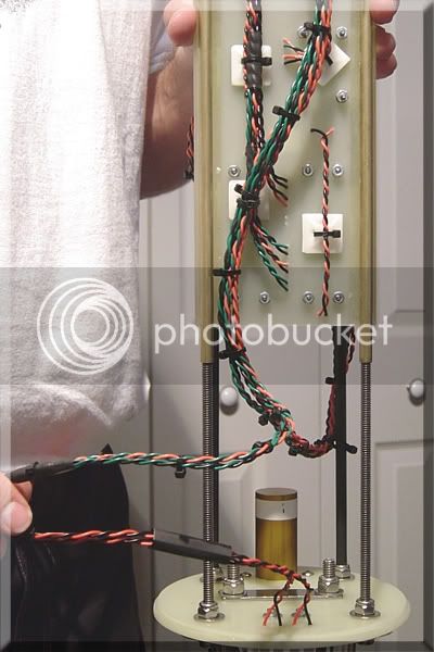
Now, on to the electronics sled. First, I soldered leads to all of the battery holders:

108solderingbatteryconnections.jpg


All connections were soldered, then heatshrinked:

109heatshrinkingbatteryconnections.jpg


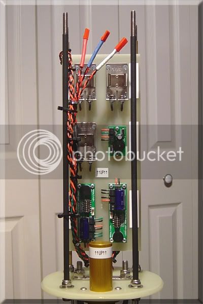
All electronics mounted, labeled, and wired:

110avionicssledwiredup.jpg


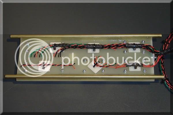
On the underside of the sled, all wires are twisted and tied/secured at regular intervals for strain relief:

111avionicssledundersidewiring.jpg
 
The completed avionics sled, installed on its rails:

114avionicssledinstalledonrailselec.jpg


And from the other side:

115avionicssledonrailsunderside.jpg


I also left a loop of wiring, to allow for easy removal of the sled:

115avionicssledonrails2underside.jpg


Connector leads were soldered to the arming switches, then heatshrinked twice. Red, white, and blue heatshrink identifies each switch, to ensure they are connected properly when the sled is installed:

116armingswitcheswiredsolderedandhe.jpg


Arming switches installed into the avionics bay:

117armingswitchesinstalled.jpg


To test the final fit and finish, I installed the electronics sled, and connected the aft endcap leads, and arming switches:

118sledinstalledintoavionicsbay.jpg


Then, I attached the forward end cap's leads, and installed the endcap.
The completed avionics bay, complete with all electronics and wiring:

119completedassembledavionicsbay.jpg


The last step, which I overlooked until now, is to drill holes on the sides of each battery mount. These will accomodate wireties, to help secure the batteries.

Then, on to the nosecone. I am trying to decide whether to add a fixed amount of weight to the nose (e.g. lead shot and eopxy), or create an adjustable system. I think a fixed amount of weight will be fine, as there won't be a wide variety of motors that I will be using. Off to do some calculations and planning!

Any suggestions on how to attach the weight inside the nosecone, or how to make a variable noseweight system would be much appreciated =)

Cris
 
This is a BEAUTIFUL rocket. You have to tell us when your launching it. Ill have to drive up for the launch.

P.S. You know there is no FSA/TWP launch in august right?
 
Lets get ready to RUMBLE!

In one corner building in with a perfect shop, Lee Scott!

In the other, using high tech fiberglass, Cris!

Ben
 
Does "UP" matter?
I see you clearly marked "UP" on the sled -- yet the altimeters are opposite orientation. Not sure what they are and if they need to be pointing up, but it looks like a problem.

Also -- why a CO2 deploy? You are not going that high and certinally don't need it for the main at low altitude. Seems to add risk IMHO.

Otherwise a really nice build!
Good luck with your L3.
 
Orientation has no effect on these altimeters. The reason that they are in opposite directions is simply so the wiring would be neater.

The "UP" label is for the backup timer. The g-switch that activates the timer is directional, so it is absolutely imperative that the sled gets installed in the correct direction.

I also canted the sled's rails ever so slightly, so that if you install it correctly it slides right down. But if you put it in backwards, its a little hard to push it down the rails.

As far as the CO2 system, I do not use it for its high altitude advantages. I have used the Rouse-Tech systems in every HPR launch since my L1 cert, and it has worked flawlessly every time. I have total confidence in the system, and give Tom Rouse props on a great design!

One of the big advantages is its very clean - no messy residue inside the rocket. Plus there's no chance of burning through a harness or melting a chute.

Also, I like the extreme precision of the system. There are no worries about using too much or too litle black powder. The amount of powder is always the same, regardless of the CO2 cartridge used. You simply fill a tiny chamber to the top each and every time.

I calculate the correct CO2 charge when I design the rocket. Then I ground test many times to confirm. After that, its a simple matter of screwing in a new CO2 cartridge for each launch.

I'm sure there is some remote chance of geting a defective CO2 cartridge, but I've never heard of it happening. Then again, you could get a defective anything... motor, altimeter, e-match, etc.

By the way, thanks for the compliments everybody! Im not sure I deserve them yet... lots of people on here much more talented than I!

Jacob... That stinks about August... I can't wait for the next launch up here. I havent been to a launch in so long! Between the constant rainstorms and the launchless August, I am suffering from withdrawl!!

Hey, if anyone has suggestions for securing wieght to the inside of the nosecone, please share =) I am thinking I will pour epoxy into the tip of the nose, and add lead shot or similar until I get the desired weight. The inside of the nosecone is of an extreamly rough texture, like chop mat, so I'm assuming the epoxy will grip very well. What do you think?

Cris
 
Cris, I must say that this thread ranks up there in both quality of construction as well as helpful information... definately an to "favorites".

Regarding the weight in the nose, why not make a variable weight system thats dependent on what motor you use? If the nosecone's bulkhead is removeable, you could slide weights down the allthread and secure them in place with nuts. Now I'm no level 3 or 2 for that matter, but that system seems like one that works well.
 
This is an impressive build thread. I will be considering this rocket and the mods you did for my L3 when I get around to it. :) Right now I'm having so much fun with L2 motors I haven't bothered to really plan out my L3. :)

For an all FG rocket kit, the price for this is pretty reasonable.
 
Jacob... That stinks about August... I can't wait for the next launch up here. I havent been to a launch in so long! Between the constant rainstorms and the launchless August, I am suffering from withdrawl!!
Cris

Me too dude! Ive been in California for months. while theres no FSA/TWP launch in august there is one in Florida city.
 
Cool build Cris! Thanx for taking the time to post your build.

Not a suggestion but just a crazy idea for nose weight.

Grab 2 or 3 of the biggest baddest bolts you can find at the hardware store, slime them up with vasoline or something and foam them into the nose cone. In theory, you should be able to remove the bolts and have some threaded foam in the NC. Then install the desired NC weight in the form of big ol knarly stainless socket head screws ( or somthing to the effect of cool hardware).

End result: Adjustable nose weight and about sixty bucks invested in bolts/screws.

Scott:kill:
 
A while back, someone asked about paint schemes. I was trying to decide whether to do something bright, flashy, and fun, or to give it more of a serious paint job, like a military look.

When I look at this rocket, its all business. Nothing fancy to the fin shape, or the nosecone. Typical form-follows-function design. So, I decided to go with a military look, sort of like a missile. But I still wanted to add a little color, so here's what I came up with...


Competitor6paintscheme.jpg
 
Holy crap thats sweet! I cannot wait to see this thing!

Ben
 
Having Six Switches for the alt bay is just asking for trouble. You got multiple points of failure. Two altimeters, two switches. NAR L3 rules has been interpreted differently, many have read it that each match needs a switch... but that is a BAD idea that I contribute to my L3 failure. I will be launching my next L3 rocket with only two switches... will join TRA if I have to.
 
Ben & Scoop - Thanks, I'm glad you like it. Drawing it is the easy part! Now, to actually make it look just like that! Hehe

N3TJM - You must have been looking at the original schematic that I posted months ago. I started another thread specifically on the subject of altimeter switches. Some 66 responses later, I decided to keep it simple and eliminate the shunt switches. If I hadn't, the backup timer would have brought the total to 8 switches!! So in the end, I used one for each alt, and one for a backup timer. Total of 3.

Thanks for the input though. I appreciate the constructive criticism.

Cris

PS I just updated the schematic on the first page of this thread. It now reflects the 3-switch design, with the addition of the backup timer.
 

Latest posts

Back
Top