spigalau
Well-Known Member
Build by: Spigalau & PyroShark aka Spyro Rocketry (a father & son team).
Ok, so first up this build is somewhat out of order, you could say upside down, but we are in New Zealand, so we do things kind of different down this way. Truth is the USPS wasn't kind to our booster tube and a replacement is being sent, so we got things underway with what we had.
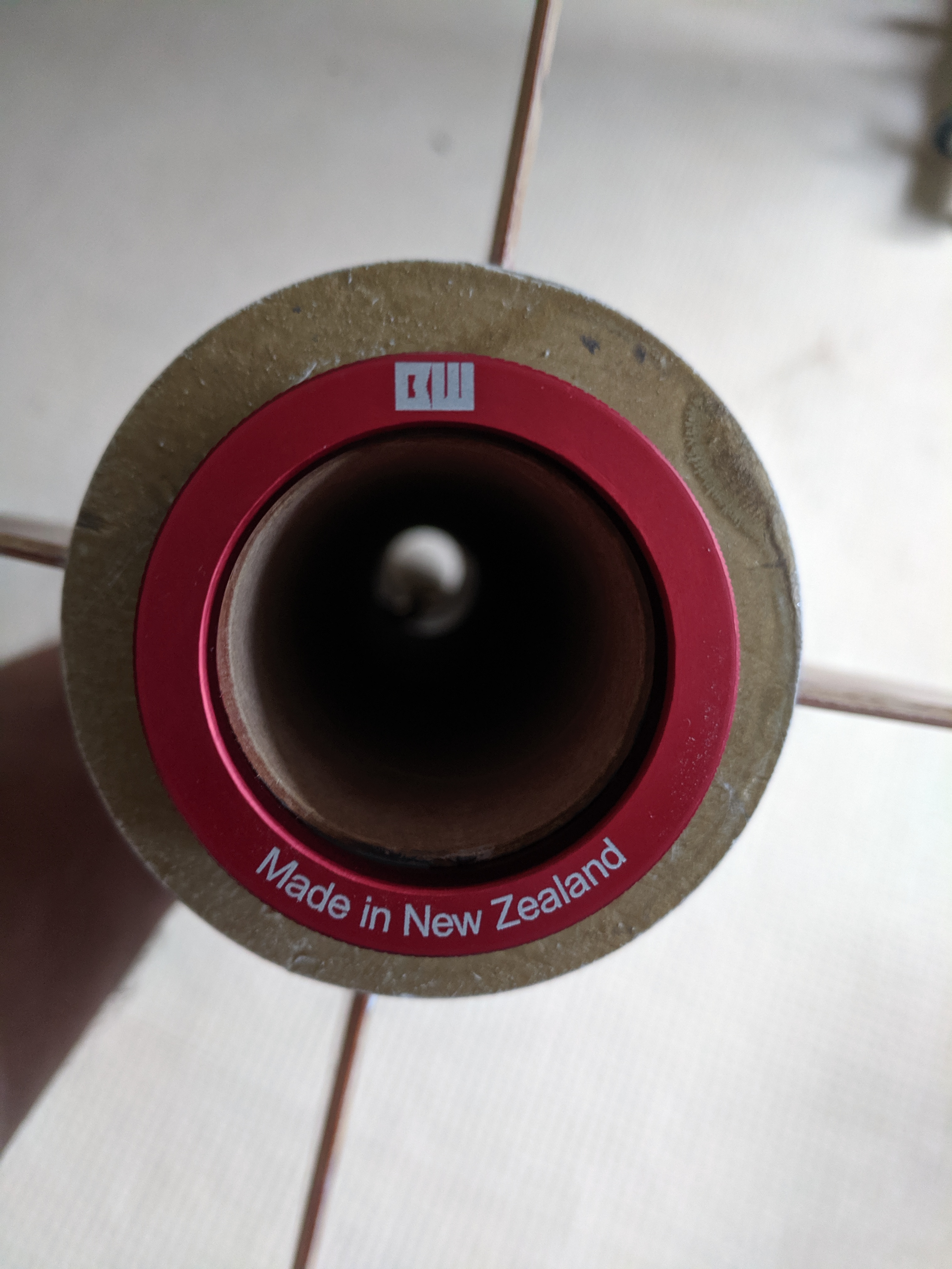
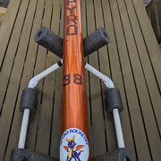
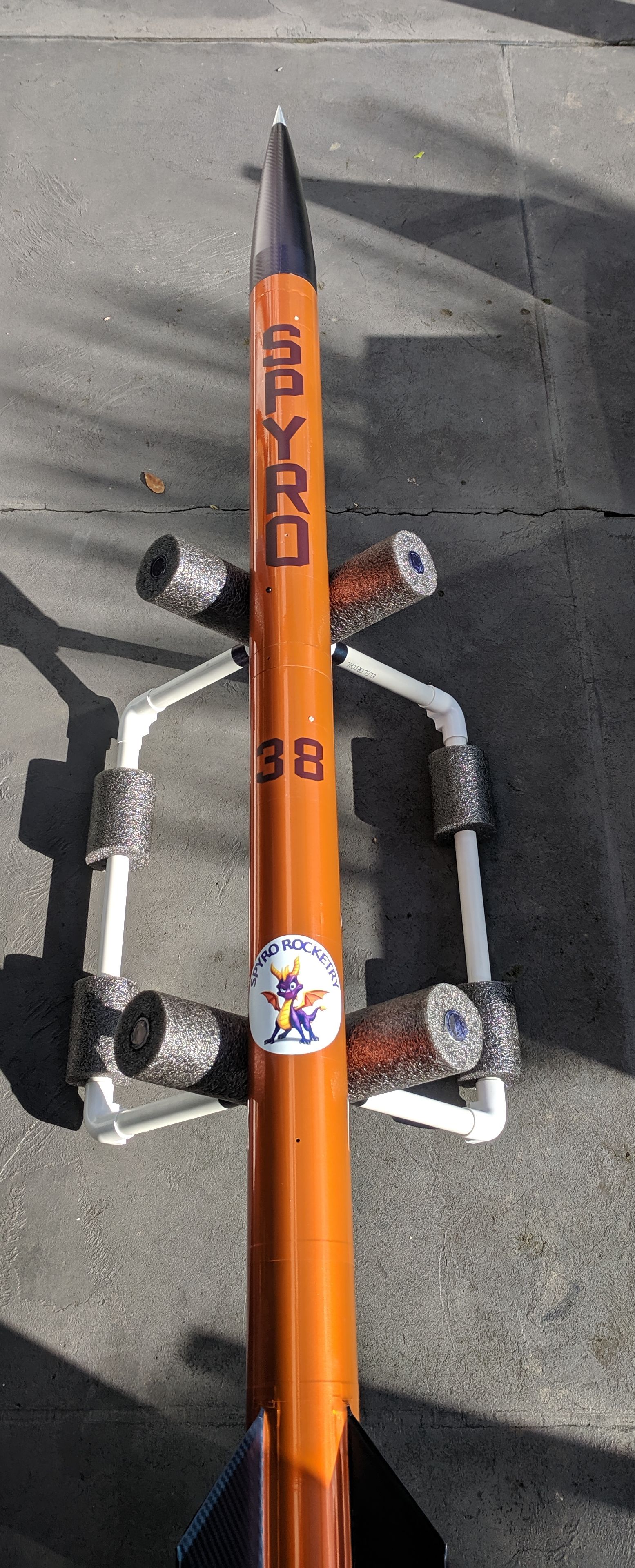
Airframe: MAC Performance 3" Scorpion XL with 5:1 Von Karman fibrewound nosecone and 30" booster tube.
Motor Mount: 38mm (much easier to source 38's in NZ than 54's)
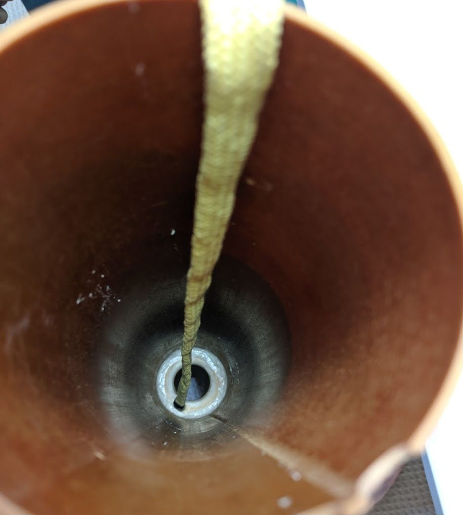
Lower Harness: OneBadHawk 25' 1/4 inch kevlar 3 loop
Drogue: 16" (or 12") X Form Parachute
Upper Harness: OneBadHawk 25' 1/4 inch kevlar 2 loop
Main Chute: 54" PML Durachute
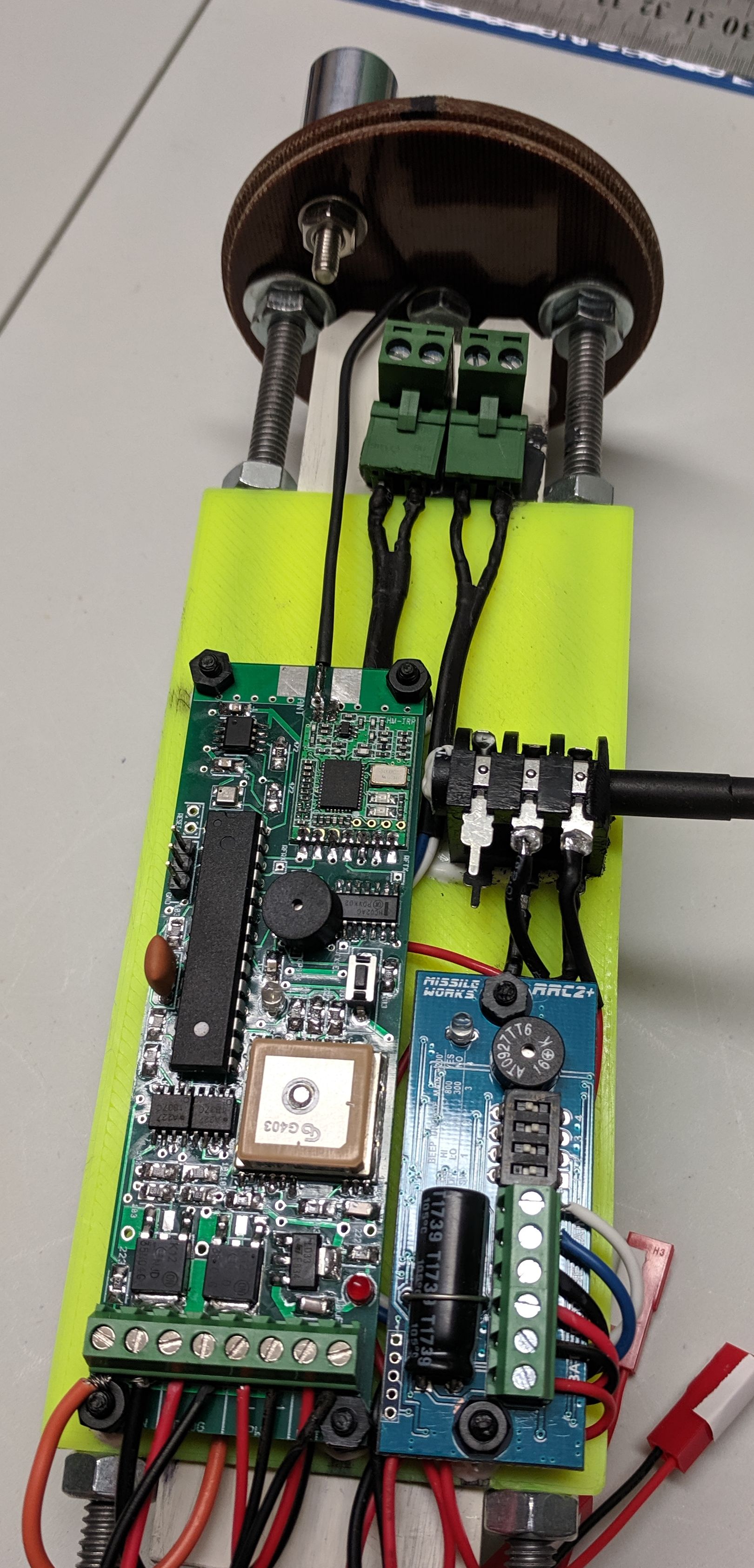
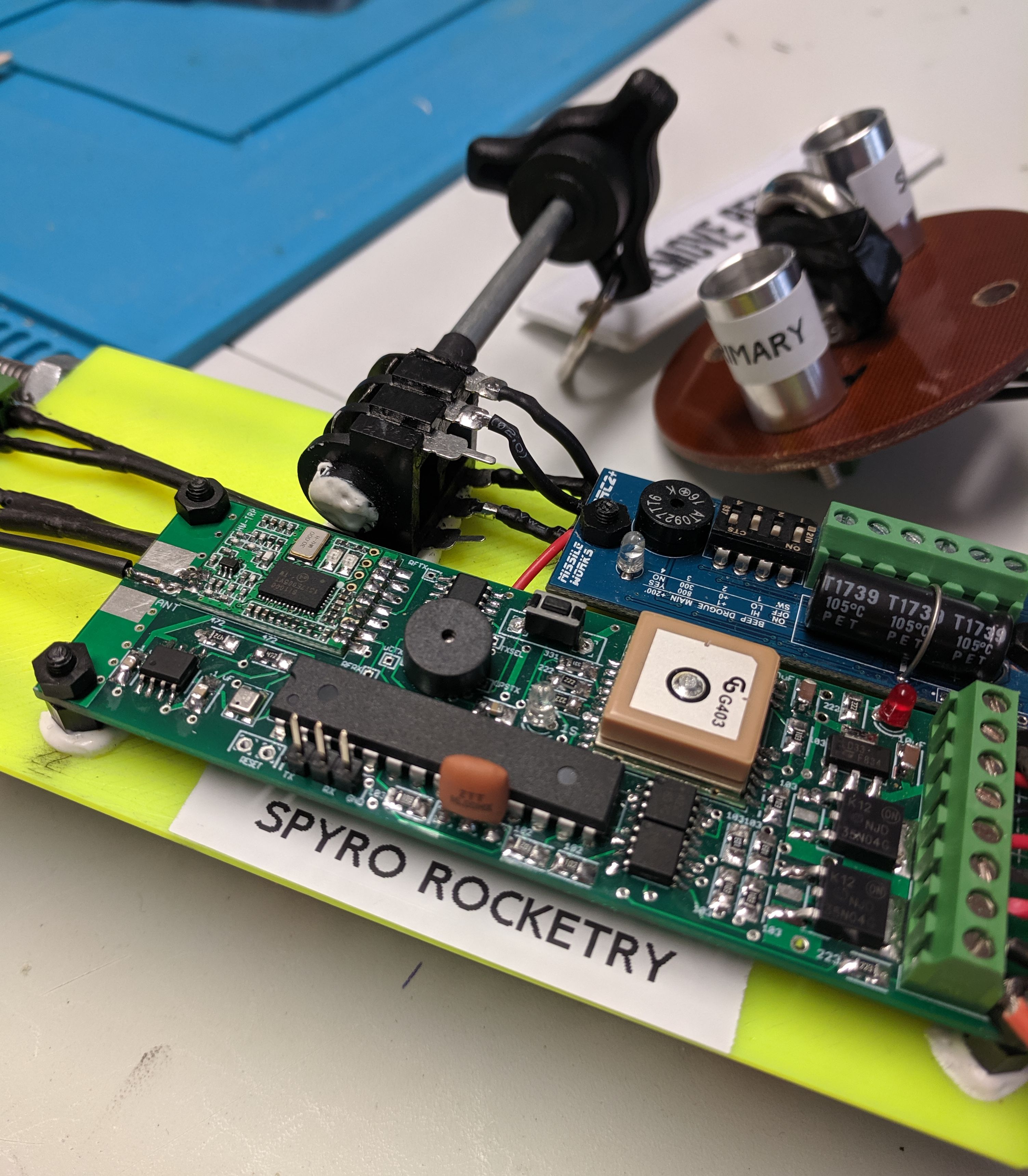
Primary Flight Computer: EggtimerTRS
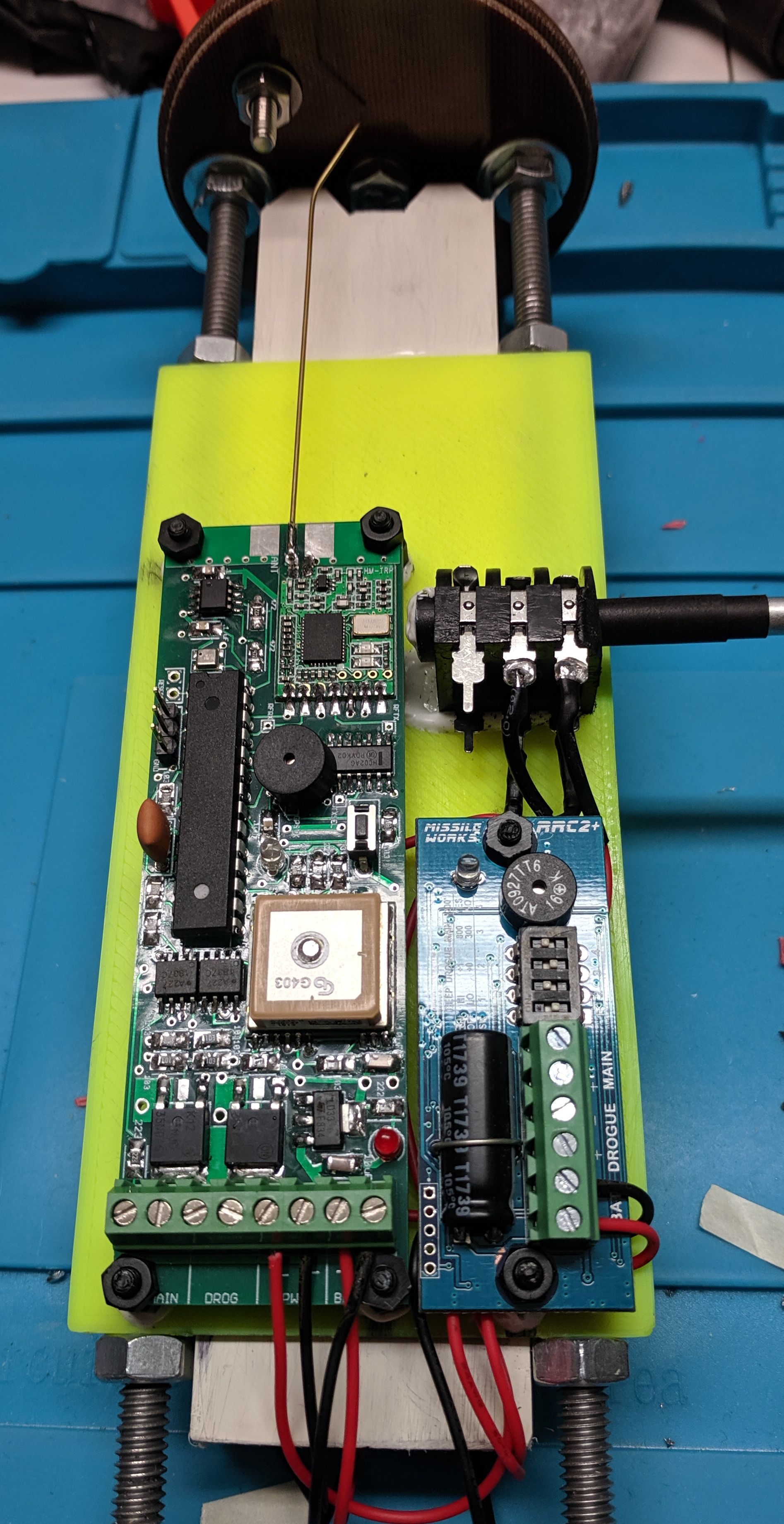
Secondary Flight Computer: MissleWorks RRC2+
Independent Altimeter: Jolly Logic 2
Name: Spyro 38 MK1
Aim: L1 / L2 certification's
Probable Launch Date: Sep 2019
So to get things underway, we started with the longest screwdriver we could buy.. all 24" of it.

Why 24"s you ask, well it's so we could still get to the nose cone screw, once we had secured the head avionics bay in to the nosecone.
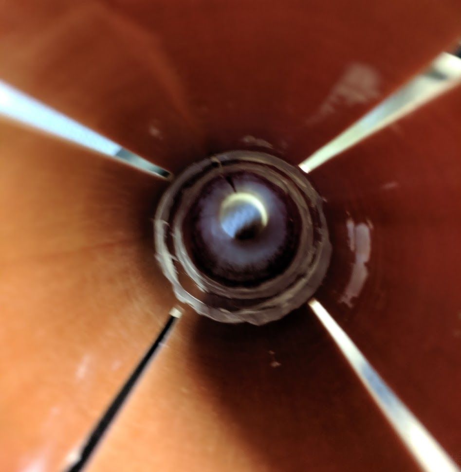
Before installing, removed out the upper eye bolt from the head bay and drilled out the centre hole to allow screw driver access to the screw.
And then putty epoxyed the upper rail bolts in place to stop them from ever coming undone.

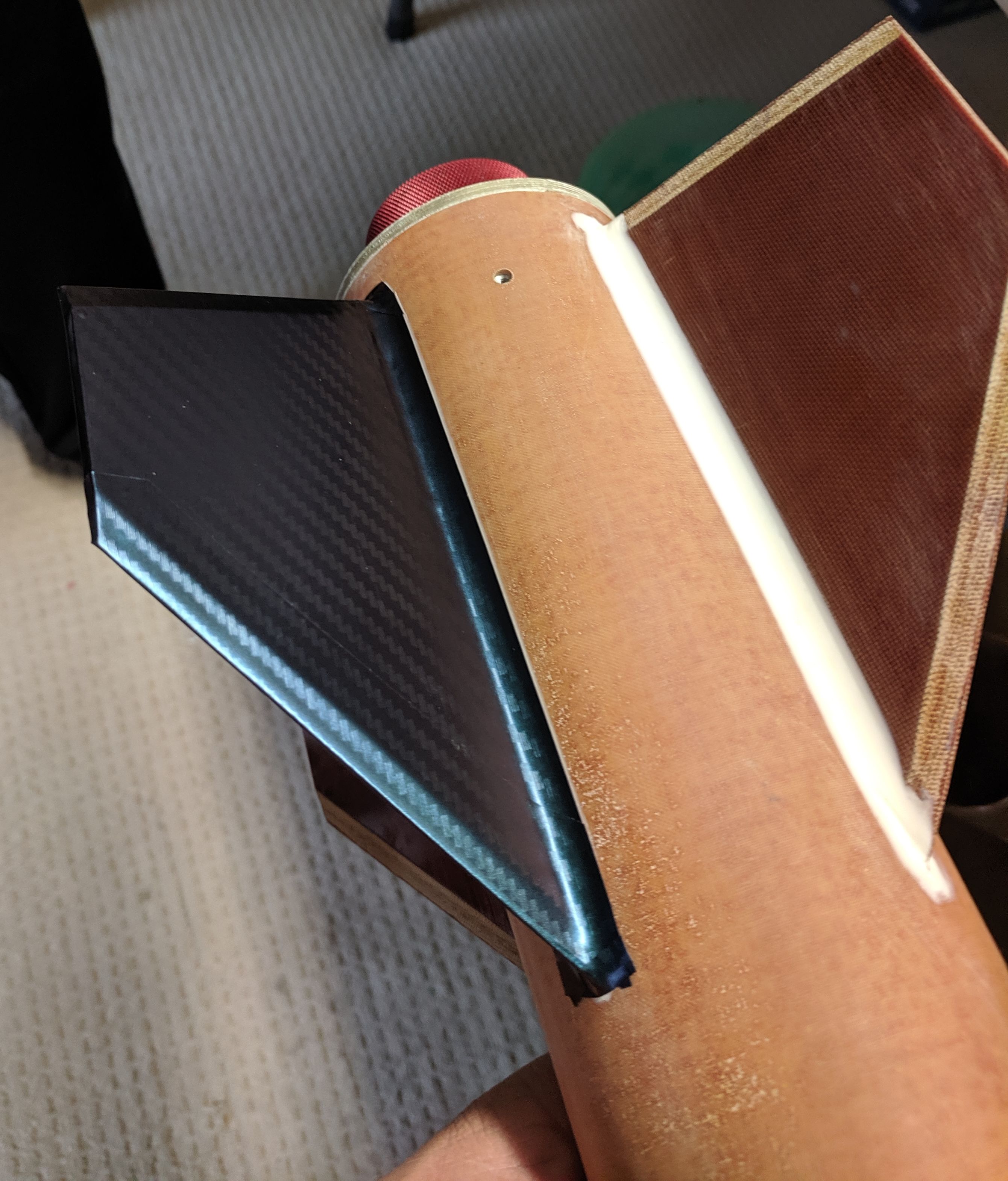
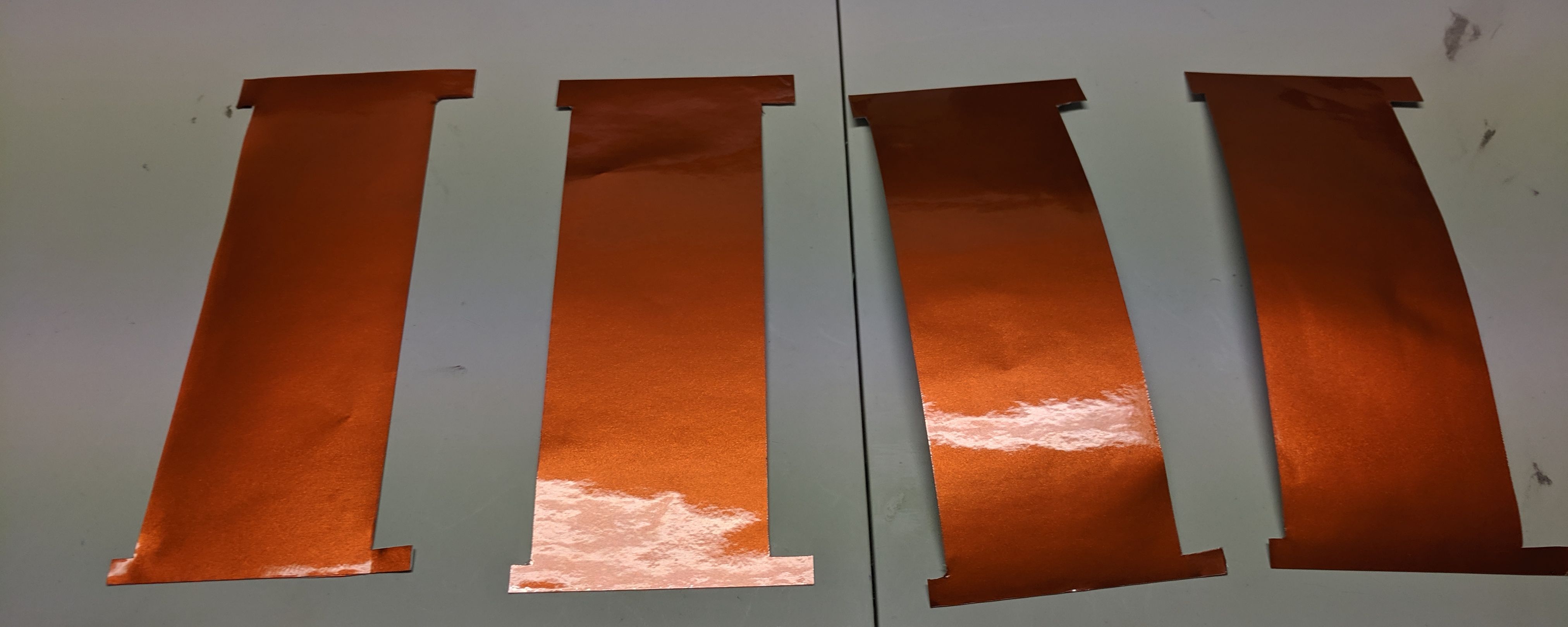
Whilst that was in the hot water cupboard curing, we started with the nosecone wrap - it's a crime to cover up the shear beauty of the nosecone - but we think the end result & appearance will be worth the effort.
So first up with the wrap on the nose, it is not as hard to do as it looks, but still a fun challenge for a wet Saturday afternoon.

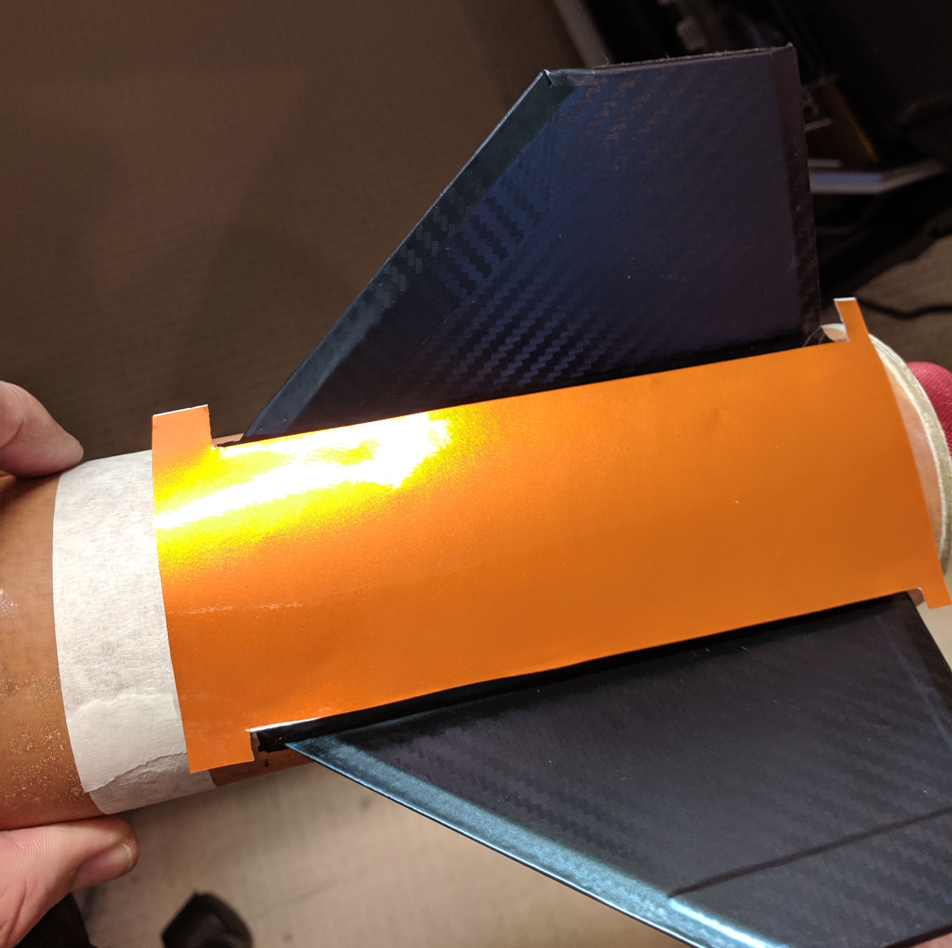
And then the fun started...

It took 2 goes to do the second section, because I (he who should know better) cut it too fine and exposed a gap between the 2 panels, so we re-did that.
And then he, who is a a 'maths' whizz, who says he was only following orders, ballsed up panel 3 by cutting the last panel too narrow. Rule of the day: Measure, Measure again, Measure again and then add 1cm (or 3/8") to your measurements.
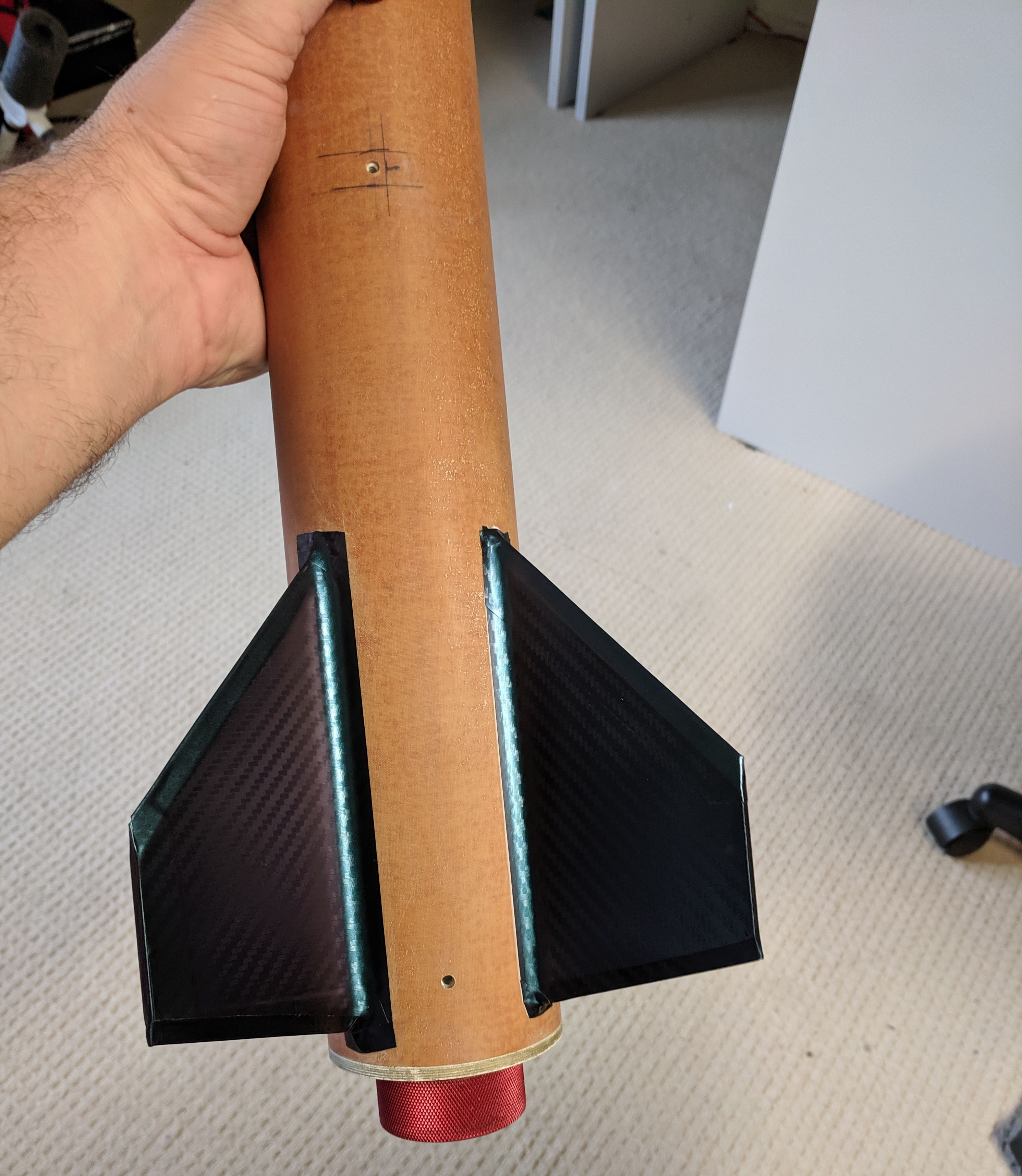
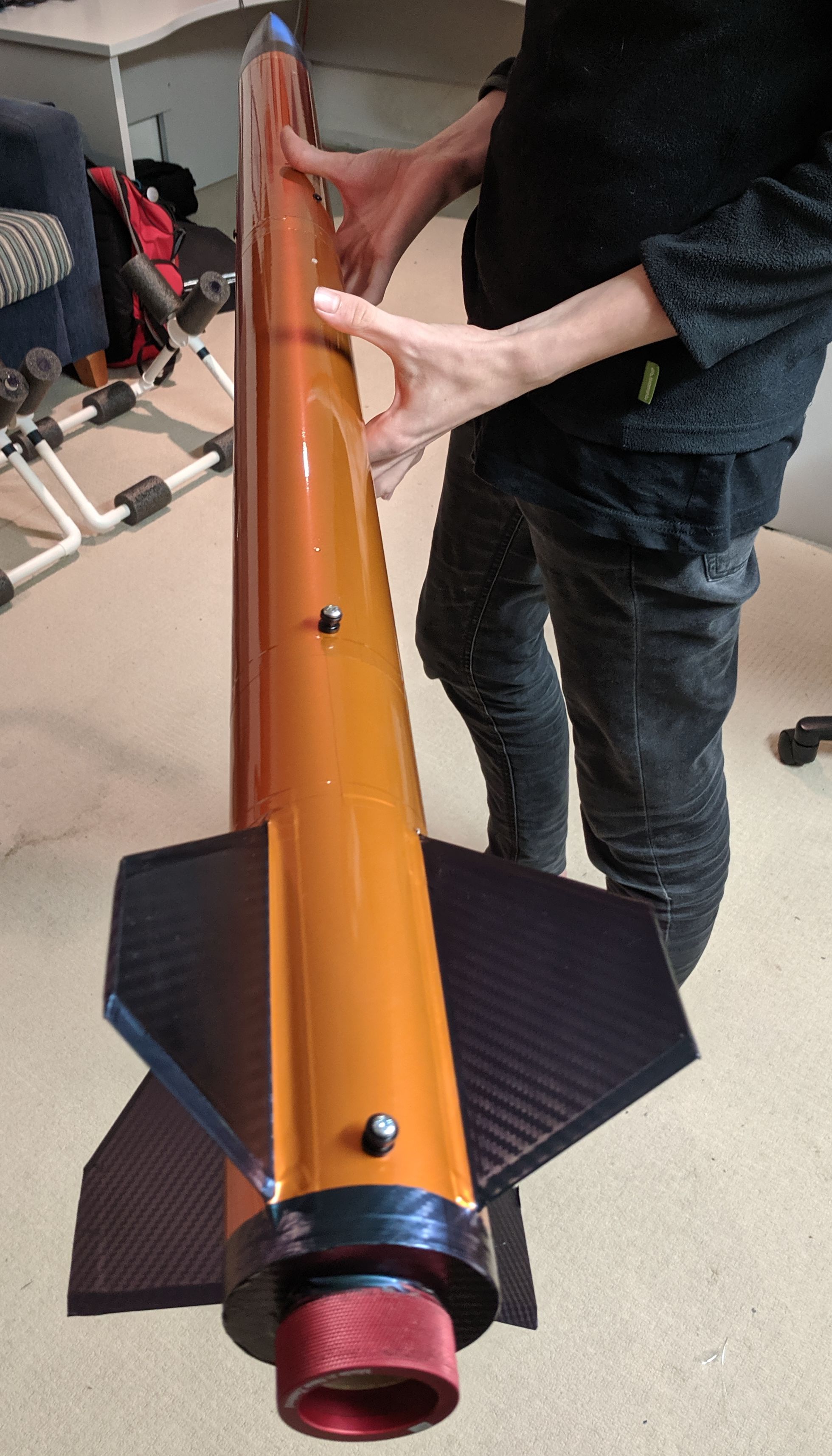
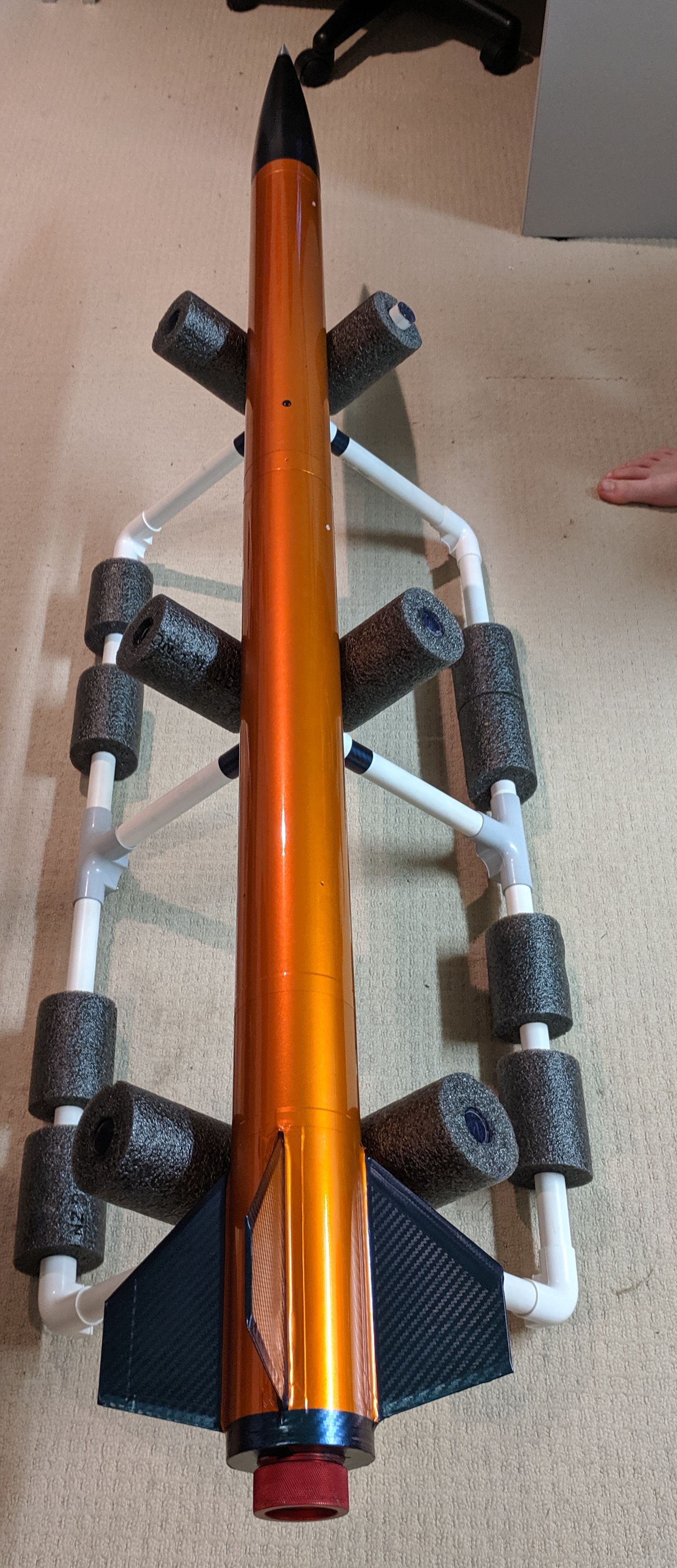
End result with tip installed was not bad for our first ever wrapping experience.

The wrap for the nosecone & fins is a Chameleon Carbon vinyl, so depending on the light either is a purple, blue or even a green.
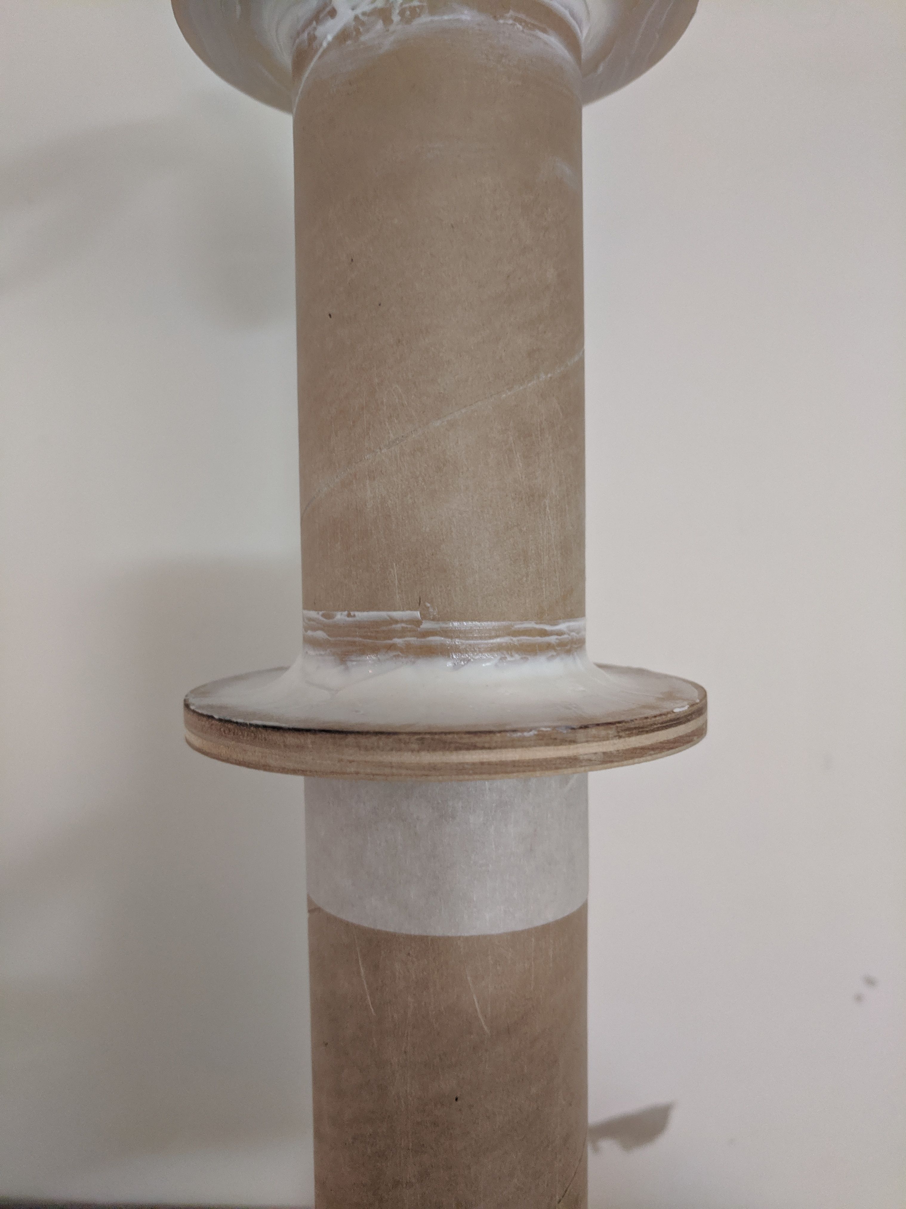
And then to finish up the night, we sanded off the upper head bay and inside the lower nose cone, cleaned it up with isopropyl, and then mixed up a batch of strong epoxy and then rammed it on home.

Now if you look real close, you will see that the lower bulk head on the headbay is upside down, this is for a reason, we wanted to leave an air gap when inserting the bay in to the nose so as to remove any pressure plunge. And it worked, once we had it in place, we cranked it tighter and then put it to bed for the night.
The next jobs on the list are:
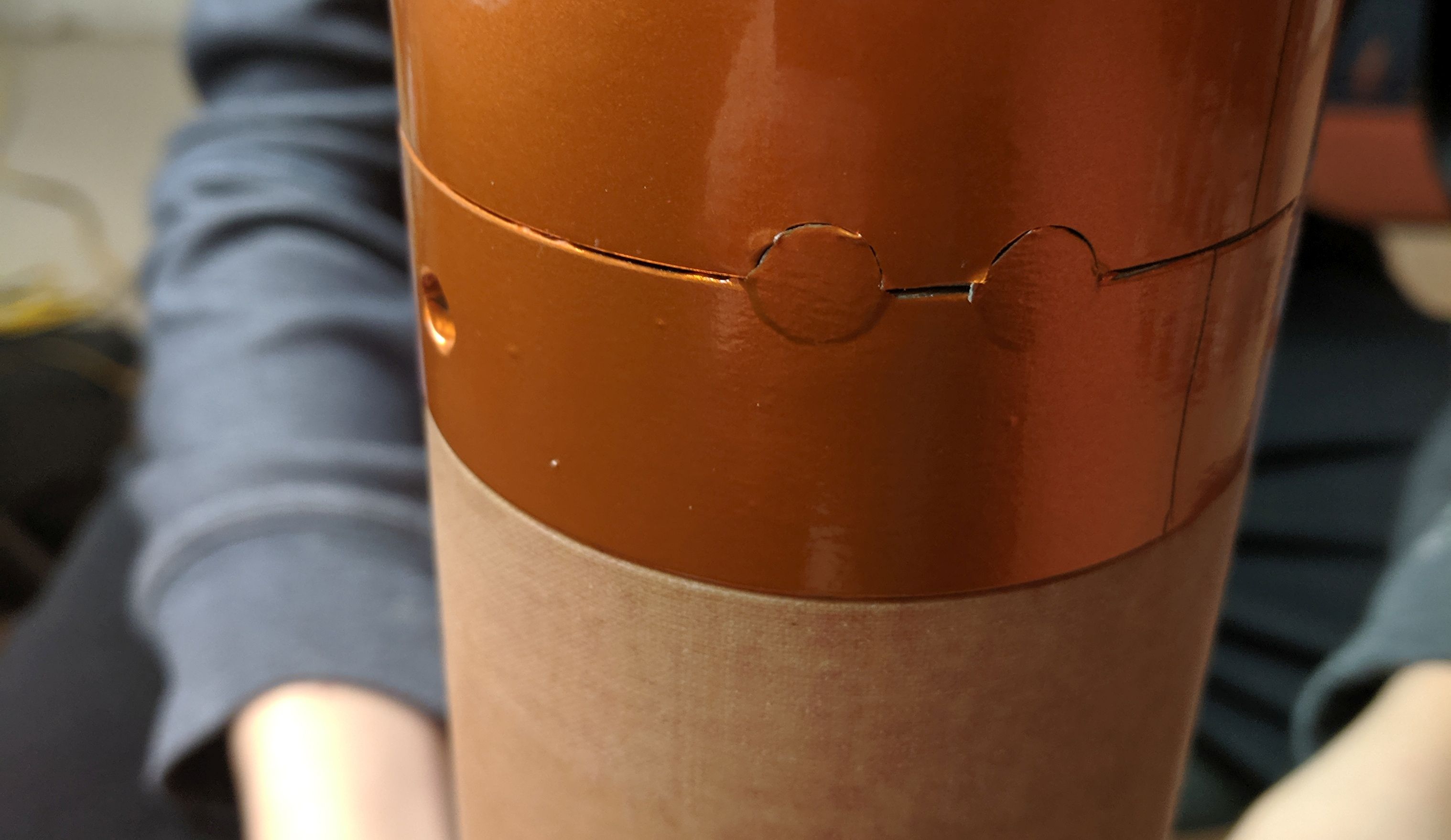
1) Payload tube - notching for ease of alignment and drilling for shear pins & plastic rivets.
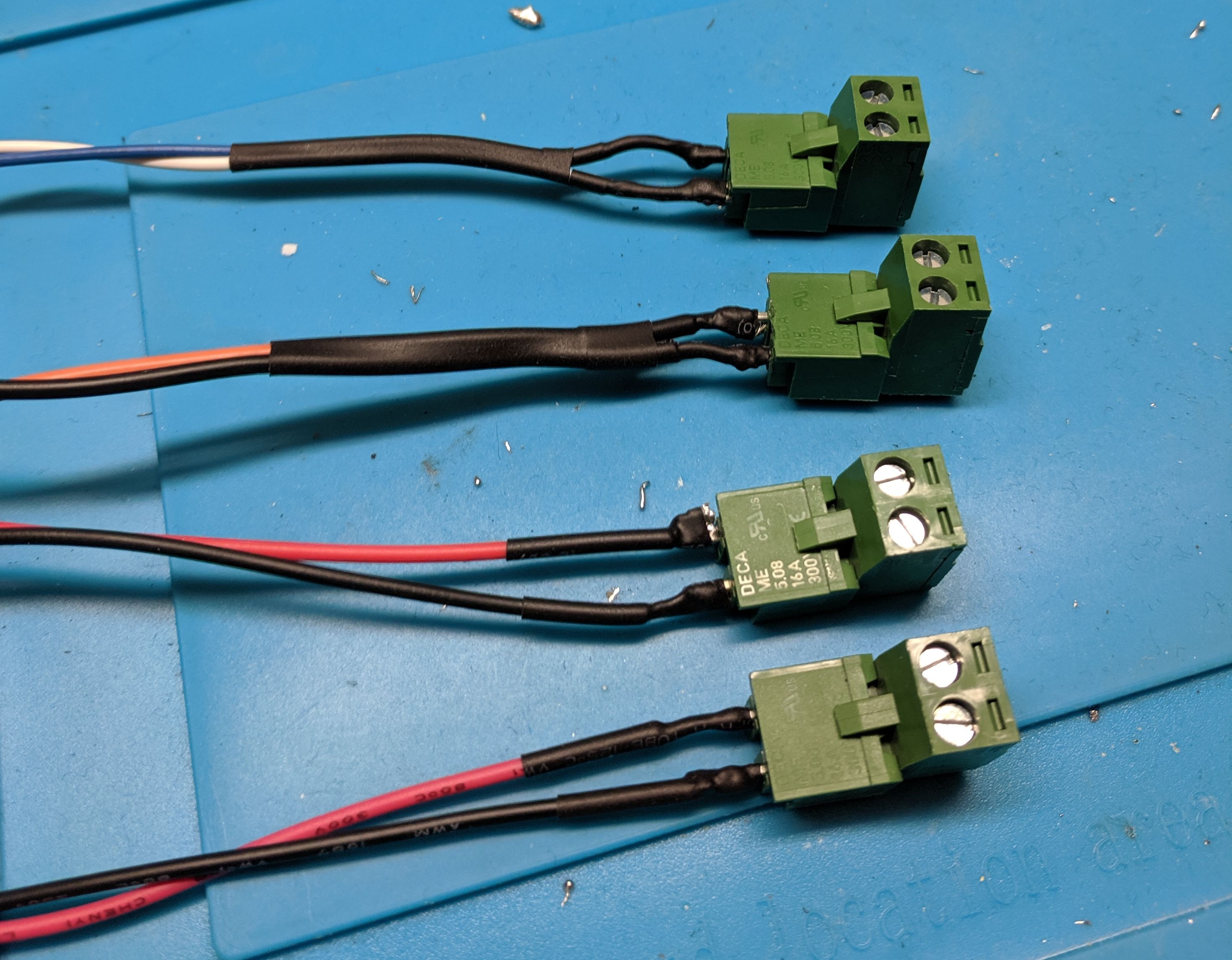
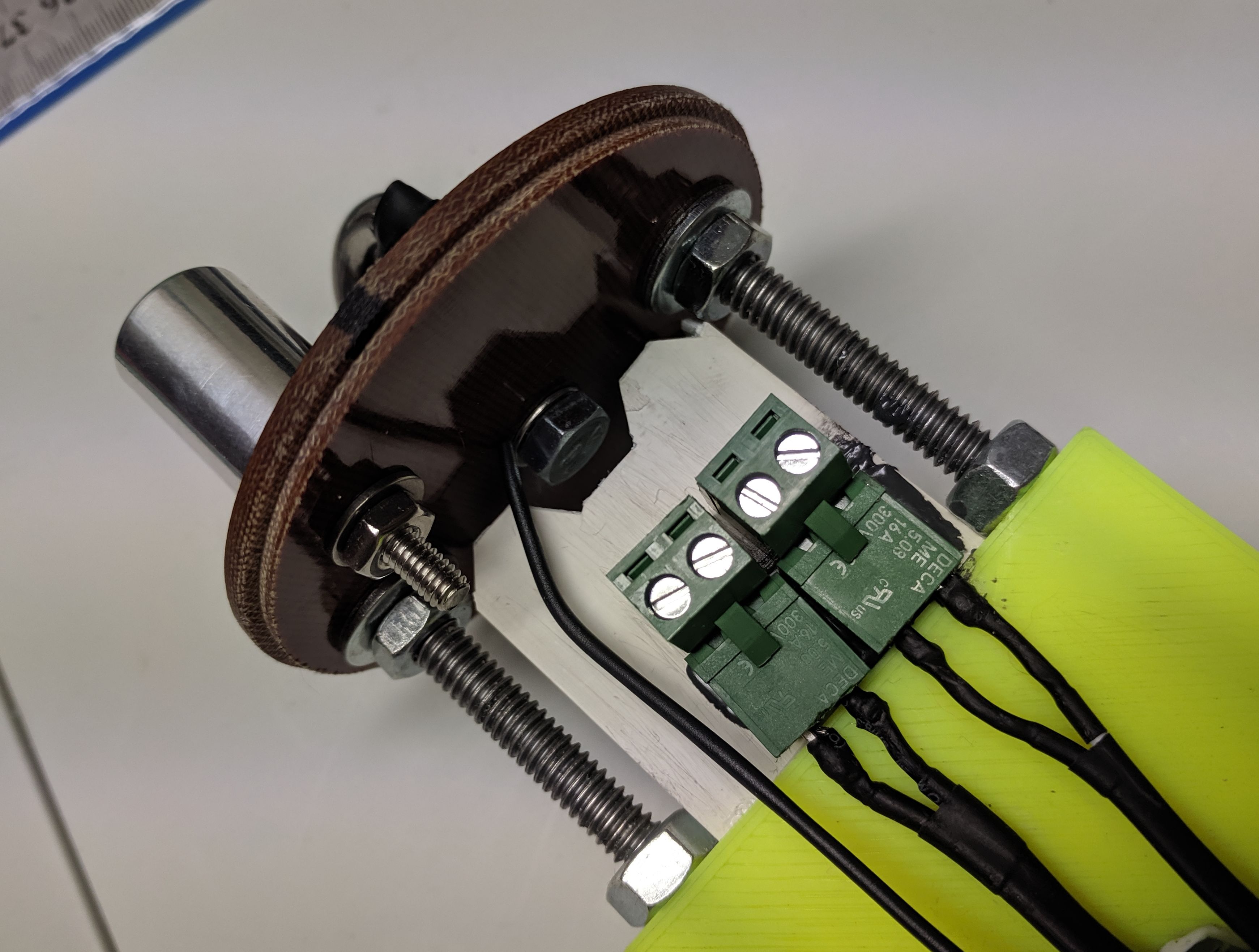
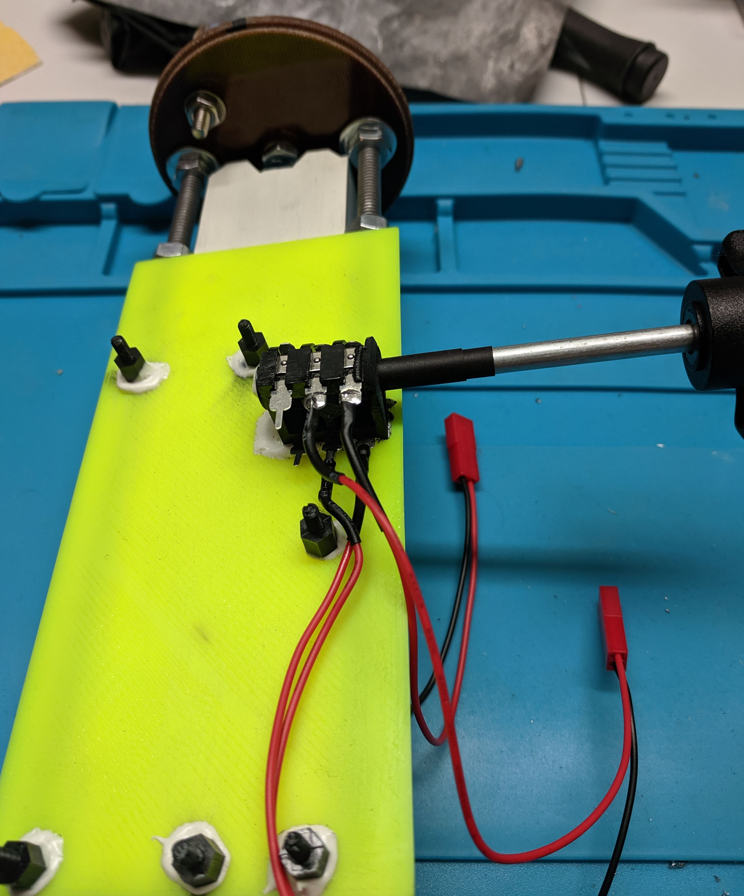
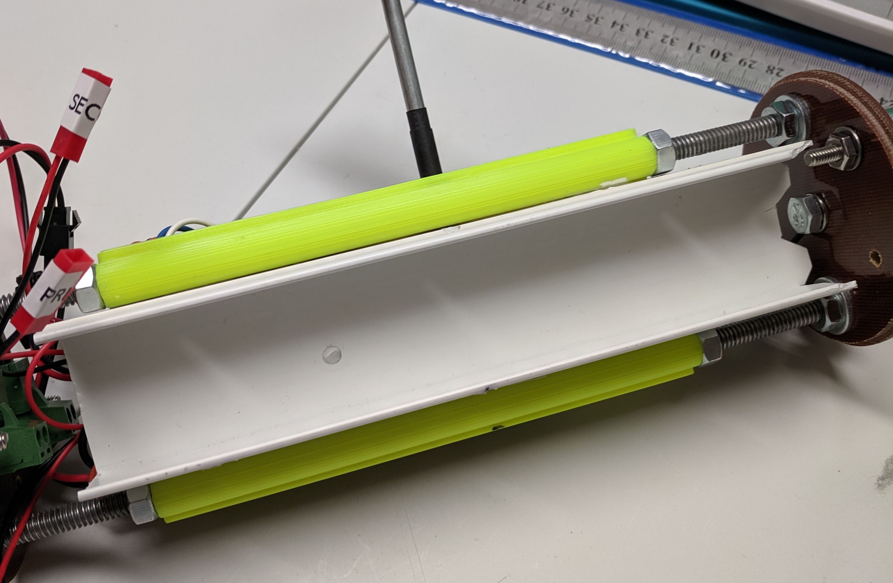
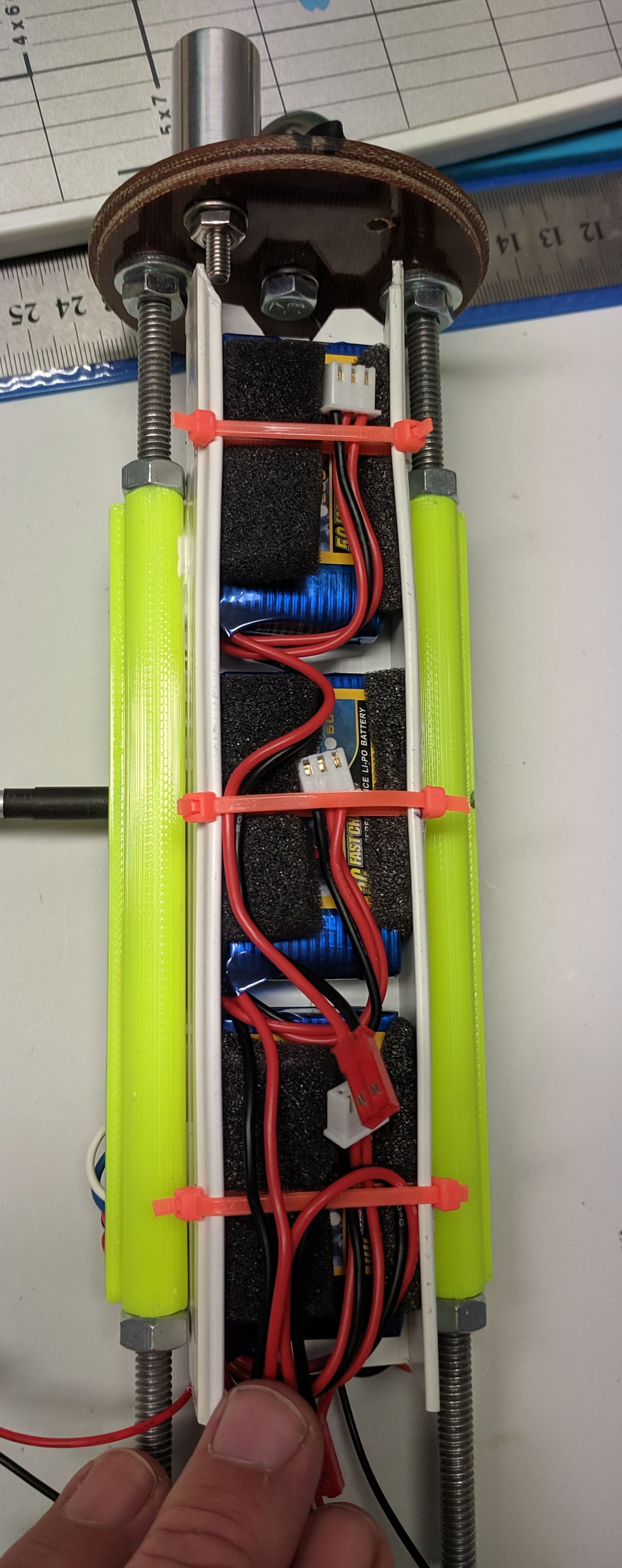
2) Avionics Bay - assembly of centre sections, installation of ejection canisters, quick release charge connectors, etc.
3) Electronics - Eggtimer TRS assembly
4) Electronics - Eggtimer Reciever assembly
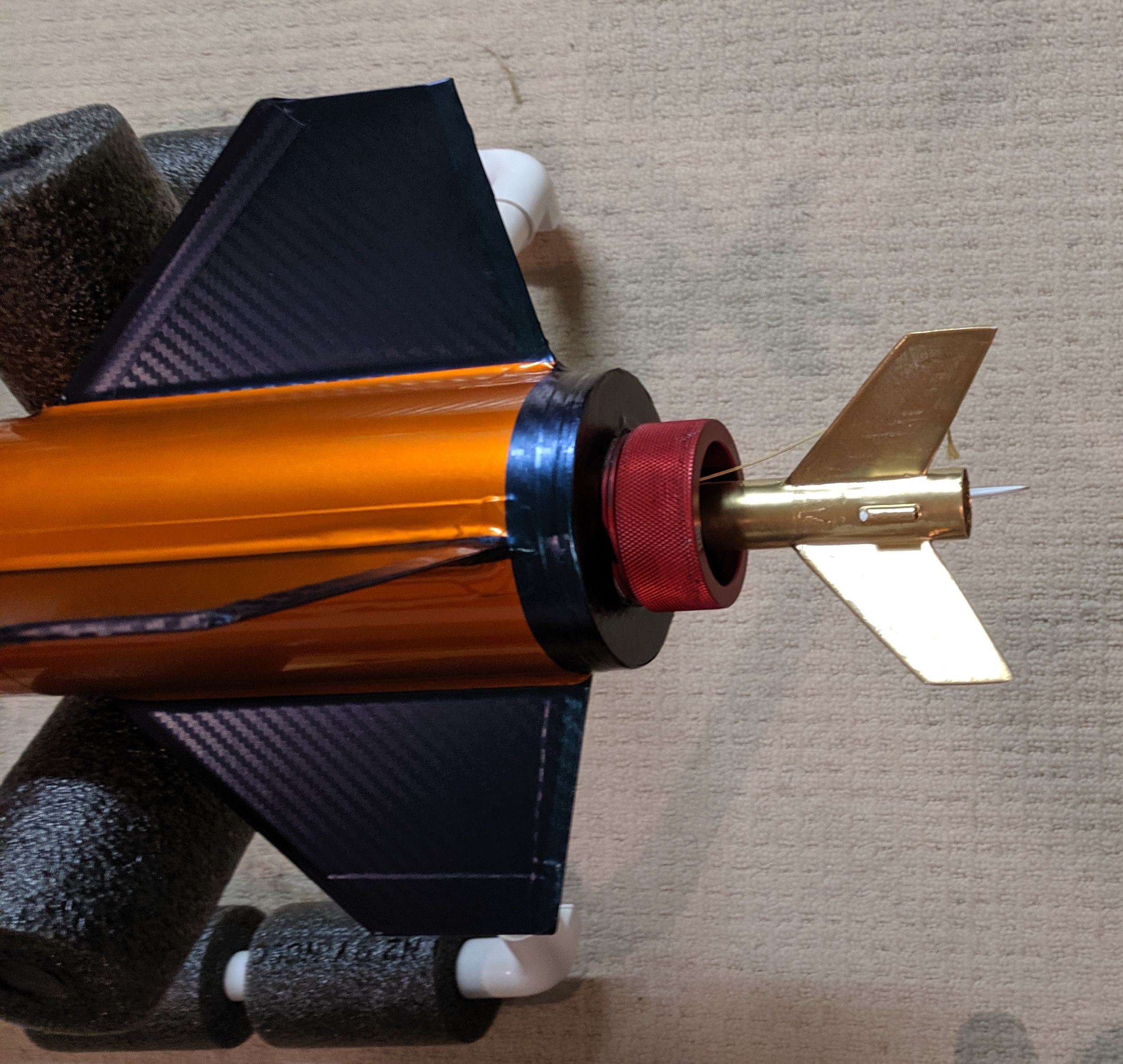
5) Motor mount - epoxy the upper ring & pin
Once the replacement booster is in NZ (2-3 weeks), we can then start on the lower end.
Our launch site closes for winter shortly, so intention is to have this ready for the spring launch day.
We would like to thank Mike (MAC), Teddy (OneBadHawk) and Cris (Eggtimer) for all of thier assistance and advice so far. The quality of all the materials has been O for awesome ().
Any questions, either PyroShark or myself will answer.
Ok, so first up this build is somewhat out of order, you could say upside down, but we are in New Zealand, so we do things kind of different down this way. Truth is the USPS wasn't kind to our booster tube and a replacement is being sent, so we got things underway with what we had.
Airframe: MAC Performance 3" Scorpion XL with 5:1 Von Karman fibrewound nosecone and 30" booster tube.
Motor Mount: 38mm (much easier to source 38's in NZ than 54's)
Lower Harness: OneBadHawk 25' 1/4 inch kevlar 3 loop
Drogue: 16" (or 12") X Form Parachute
Upper Harness: OneBadHawk 25' 1/4 inch kevlar 2 loop
Main Chute: 54" PML Durachute
Primary Flight Computer: EggtimerTRS
Secondary Flight Computer: MissleWorks RRC2+
Independent Altimeter: Jolly Logic 2
Name: Spyro 38 MK1
Aim: L1 / L2 certification's
Probable Launch Date: Sep 2019
So to get things underway, we started with the longest screwdriver we could buy.. all 24" of it.
Why 24"s you ask, well it's so we could still get to the nose cone screw, once we had secured the head avionics bay in to the nosecone.
Before installing, removed out the upper eye bolt from the head bay and drilled out the centre hole to allow screw driver access to the screw.
And then putty epoxyed the upper rail bolts in place to stop them from ever coming undone.
Whilst that was in the hot water cupboard curing, we started with the nosecone wrap - it's a crime to cover up the shear beauty of the nosecone - but we think the end result & appearance will be worth the effort.
So first up with the wrap on the nose, it is not as hard to do as it looks, but still a fun challenge for a wet Saturday afternoon.
And then the fun started...
It took 2 goes to do the second section, because I (he who should know better) cut it too fine and exposed a gap between the 2 panels, so we re-did that.
And then he, who is a a 'maths' whizz, who says he was only following orders, ballsed up panel 3 by cutting the last panel too narrow. Rule of the day: Measure, Measure again, Measure again and then add 1cm (or 3/8") to your measurements.
End result with tip installed was not bad for our first ever wrapping experience.
The wrap for the nosecone & fins is a Chameleon Carbon vinyl, so depending on the light either is a purple, blue or even a green.
And then to finish up the night, we sanded off the upper head bay and inside the lower nose cone, cleaned it up with isopropyl, and then mixed up a batch of strong epoxy and then rammed it on home.
Now if you look real close, you will see that the lower bulk head on the headbay is upside down, this is for a reason, we wanted to leave an air gap when inserting the bay in to the nose so as to remove any pressure plunge. And it worked, once we had it in place, we cranked it tighter and then put it to bed for the night.
The next jobs on the list are:
1) Payload tube - notching for ease of alignment and drilling for shear pins & plastic rivets.
2) Avionics Bay - assembly of centre sections, installation of ejection canisters, quick release charge connectors, etc.
3) Electronics - Eggtimer TRS assembly
4) Electronics - Eggtimer Reciever assembly
5) Motor mount - epoxy the upper ring & pin
Once the replacement booster is in NZ (2-3 weeks), we can then start on the lower end.
Our launch site closes for winter shortly, so intention is to have this ready for the spring launch day.
We would like to thank Mike (MAC), Teddy (OneBadHawk) and Cris (Eggtimer) for all of thier assistance and advice so far. The quality of all the materials has been O for awesome ().
Any questions, either PyroShark or myself will answer.


")