(modified) RW Mongoose 29 - 29mm MD "Altitude Seeker": 16,000' & mach 2

The Rocketry Forum

Help Support The Rocketry Forum:

This site may earn a commission from merchant affiliate links, including eBay, Amazon, and others.

RocketHunter

Well-Known Member
Joined
Jun 15, 2013
Messages
390
Reaction score
3
For the past few MD builds I've done, I've focused on shaving weight for maximum peak speed through using the flying-case design. Unfortunately, while they do go very fast and accelerate like nothing else, I haven't gotten close to the altitude I was expecting with them. Limited to URRG's 18K waiver, getting the highest possible altitude wasn't my goal, as even a 38mm MD can break 18-20k if designed right.

When RW put the 29mm Mongoose with a filament wound 2-piece nosecone, I new it was time to try to make an ultra-performance 29mm MD. Another nice aspect I realized was that, even optimized to perfection, a 29mm motor will assuredly never break an 18k waiver. Thus, for this build I have decided to forgo my usual flying-case design and go for as efficient and aerodynamic as possible, and for optimum weight rather than as light as possible.


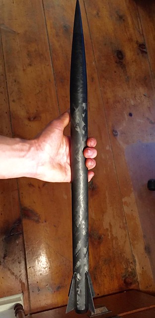
Simulation says mach 2 and 16,000' with a CTI 6GXL I243-WH. I expect to fully get that speed, but my realistic hope for altitude is to top 14k. Maximum altitude means minimum volume, and an optimal weight of around ~7 oz. To achieve this, I pack a lot of stuff into a tiny area. The one-piece airframe is only 15.5" long, and houses a ~14.4'' motor casing. A 2.5'' coupler is glued into the top of this airframe, and acts as both the nose cone coupler, electronics/tracking bay, and thrust ring for the motor (since the CTI 29mm tail cone closure does not have a thrust ring). The fins are 0.05" thick 7-layer CF plate quickly made with Aeropoxy, and an antique cast-iron book press, with surprisingly good results - I used 19.8g of fabric and the finished plate only weighed 30.3g - giving me a nice ratio of 35% epoxy by weight.


I went with four fins for this design as I like the look and feel they are more dynamically stable (also, if one shortens the fin span when going from 4 to 3 fins to equalize stability between the two, it seem like 4 fins are no less efficient than 3). Also, it means less span as less chance for flutter - finsim puts flutter for these tiny things at over M3, so I should be quite safe. The nosecone will house 10' of 400 lb kevlar, and an 8'' or 12'' chute - deployed by altimeter at apogee. The coupler is 2.5'' long, and uses an ABS 3-D printed mount to hold a Perfectflight Stratologger CF, BRB beacon, 1s Lipo, screw switch, and integrated charge well. Took a bit of shaving to get it to fit, but its perfect now!


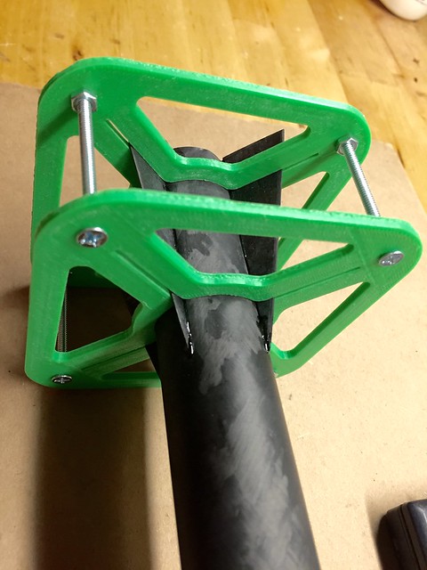
The CTI tail-cone closure is cool, but interestingly is flush with no thrust ring. To smooth the transition, I beveled the CF tube to match the taper in the closure.


The FWFG nose cone had a lot of extra epoxy in it, so I carefully drilled it out to open up some precious space. It will be filled with some metal noseweight, either BB's or maybe something a bit more efficient. If anyone has a nice method for making dense and compact noseweight I'd love to hear it!


Since I'm only using a small section of the Mongoose airframe and coupler, I have lots of leftover parts:


Depending on how long this build takes, I'm strongly considering building a nearly identical, 3-finned version but using the flying case format, and then fly them both on the same day and same motor to get a nice comparison in the performance of the two design philosophies.


While I'm posting pictures, I thought I might add a picture of my last, much less optimized 24mm MD "Pink Panther Mini", which should be a lot of fun on CTI 24mm G's - motor eject with an eggfinder in the payload.


Tomorrow I will be beveling the fins, lightening and gluing in the coupler tube, and maybe even tacking the fins! Any comments/ideas/suggestions welcome! :smile:

View attachment 29mm_MD.ork
 
Last edited:
Epoxy and zinc powder for nose weight! Same zinc powder used for EX motors...check out eBay.
 
It will be filled with some metal noseweight, either BB's or maybe something a bit more efficient. If anyone has a nice method for making dense and compact noseweight I'd love to hear it!

View attachment 278571


Look here : https://www.rocketryforum.com/showt...uminum-interstage-amp-NC-s-pellet-press/page2

Post # 47, best I could find for my project and most all minimums.Lead powder, very clean. It is so close to theoretical density of solid block of lead, it doesn't get any better, unless using gold or un-obtainium...LOL

Start by mixing small amount of epoxy and adding powder to it. Mix consistency of propellent/cookie dough, roll into balls or snakes, drop into NC, tap into final position with dowel/stick.
 
Last edited:
Look here : https://www.rocketryforum.com/showt...uminum-interstage-amp-NC-s-pellet-press/page2

Post # 47, best I could find for my project and most all minimums.Lead powder, very clean. It is so close to theoretical density of solid block of lead, it doesn't get any better, unless using gold or un-obtainium...LOL

Start by mixing small amount of epoxy and adding powder to it. Mix consistency of propellent/cookie dough, roll into balls or snakes, drop into NC, tap into final position with dowel/stick.

Thanks, that looks like a great solution. Ordered and will be used on future projects! For this one though, I got impatient and went with stuff I had lying around :wink:


First thing to do was work on the coupler/electronics section. I drilled radial holes in the base of the coupler for two reasons: to shave a bit of weight, and to provide little mechanical grips for the epoxy - the coupler will be taking the full force of the motor thrust so I'm not taking any chances. I then sanded and roughed it up thoroughly with 120 both inside and out. I also drilled and tapped the electronics sled and coupler for 4-40 set screws, which hold the bay in place and sit flush to allow the NC to slip over them:


Pulled the electronics back out, and masked to keep that nice CF tube clean of epoxy.


I then mixed up some proline, as with the FWCF tube much of the motor casings heat (seems to vary, sometimes its very little, other times quite a lot) will be conducted up to this joint, and as stated previously I'm not taking any chances with this piece. You can really feel the conductivity difference - the CF warms up to your body temp really quickly in your hand, noticeably faster than comparable FG tubing.


Next, I moved on to the problem of nose-weight. To achieve maximum altitude, there is a careful balance between optimized fins and fudging extra stability to guarantee a nice and vertical flight. My goal was to keep stability above ~2 cals from liftoff to burnout; to do this with my four 15/16'' tall fins, ~1 oz of noseweight is required. Interestingly, while playing around with OR I discovered two things: that its stability calculations/plot takes into account very low speed and wind. Increasing either the wind, or decreasing the launch rail length (lowering the speed off of the rail) lowers the initial stability - just as it should. Very cool, and useful!


To fashion the nose-weight, I decided to melt down some plumbing solder (density ~7g/cc, about equal to steel) and form it in a clay mold to exactly fit the drilled out cavity in the tip of my NC. Surprisingly, it turned out quite nicely!


It fit in the NC beautifully! I then drilled a small hole through it, allowing it to double as my harness anchor.


I then mixed up some Aeropoxy structural adhesive, as I find its a bit stronger and more resilient than other stuff (and temp/heating isn't a concern here). I filled up a syringe, and lathered the piece in epoxy. Once it was laid down, I put a nice little fillet around the perimeter:


Final step for the day was to further bevel the fins by hand, being very careful not to take any more off than necessary as my fins are already as small as possible, and even a 1/32" shorter will have a noticeable and detrimental effect on my stability. They're not much, but how much can you do on 0.05'' thick fins? :lol:


Tomorrow I hope to wire up the electronics bay, drill the miscellaneous access/vent holes, and tack on the fins! :smile:
 
Last edited:
Yes, it does, but perhaps too conservatively. Run the same sims in RASAero, and you may see a big difference in initial stability.

https://www.rocketryforum.com/showthread.php?130690-Affect-of-mach-on-CP&p=1529246#post1529246

Yeah, I've experimented with RASAero in the Past, and while it seems to be very good at predicting altitude/speed, I'm still a bit leery of its stability calculations. With the new update, though, maybe I'll give it a whirl to see what is says for this rocket.


I didn't get much accomplished today; just assembled my fin guides and tacked on the fins with Proline 4500 - again just to be on the safe side with the motor heat. It will also be used for the fillets - probably around 1/4'' - 3/8'' radius. It's a bit brittle for rough landings, but at least it won't soften if the motor heats up a lot. Its too bad that most MD's end up far enough away that by the time you get to them, its too late to tell how hot the motor casing/airframe was. Maybe on a larger project, with more room to spare, one could measure how hot the airframe gets during/after the flight! Hmmm, my AIM XTRA does have 2 sensor inputs :smile:

Every time I pick the fins up, I'm just amazed at how tiny they are! They're only about 1.6 grams each, and 15/16'' tall, and yet they have to keep the rocket stable and survive through mach 2 flight :y: I trust in my sims, as I should have ~2 cals of stability and generous stiffness margins for flutter, but not having done the calculations I would never have really believed they'd be viable :shock: The only way to know for sure will be when I fly it!


Right now, with the 1 oz of nose-weight its looking like it'll come in around 7 oz (~200g) fully loaded sans motor, which puts me about ~0.5 oz above optimum weight. Not too unfortunate as the optimum weight increases with higher drag, so I'd rather be a bit over than a bit under anyway.
 
Last edited:
Yeah, I've experimented with RASAero in the Past, and while it seems to be very good at predicting altitude/speed, I'm still a bit leery of its stability calculations. With the new update, though, maybe I'll give it a whirl to see what is says for this rocket.

Fixed in RASAero II. In fact, in my opinion RASAero II now has the best supersonic CP predictions. RASAero II CP comparisons with wind tunnel data, including at Supersonic Mach numbers, for the ARCAS sounding rocket are included below.

Take it for a spin! I'd also keep maintaining a 2.0 calibers stability margin at all Supersonic Mach numbers.


Chuck Rogers
Rogers Aeroscience

View attachment RASAero II Comparisons with ARCAS CP and CD Data.pdf
 
Last edited:
To fashion the nose-weight, I decided to melt down some plumbing solder (density ~7g/cc, about equal to steel) and form it in a clay mold to exactly fit the drilled out cavity in the tip of my NC. Surprisingly, it turned out quite nicely!


It fit in the NC beautifully! I then drilled a small hole through it, allowing it to double as my harness anchor.


I then mixed up some Aeropoxy structural adhesive, as I find its a bit stronger and more resilient than other stuff (and temp/heating isn't a concern here). I filled up a syringe, and lathered the piece in epoxy. Once it was laid down, I put a nice little fillet around the perimeter:

Nice. Very nice.

Next time, you could use a heavier alloy, like 62% lead to 38% tin (or 38% solder) by weight. This will melt at about 362°F, and have a density of about 9.3-9.4 g/cc. (Modern lead free solder is mostly tin, with a few percent silver and/or antimony, which would make an insignificant difference, probably for the better.)

I had another thought, maybe for another project.

Drill holes for two rods across the NC tip, perpendicular when viewed along the axis, but offset in height. Epoxy in rods. Mix a batch of the allow above, and just pour it directly into the NC, covering the cross rods. If you pour it at not much above its melting point, any FG or CF material should be able to take the temperature easily. If you want to use it as an anchor, just make that loop around the lower rod from wire rope (which is steel, so the heat will be no problem.)
 
Tungsten powder + epoxy works pretty well. 19.25g/cc for tungsten. Lead is 11.34... You can find tungsten powder at golf supply places as it is used for weighting heads. Tungsten in epoxy has approximately the same density as solid lead. IF you want higher density, drop some solid tungsten weights in there. You could even make a form fitting casting of tungsten in lead.

I apologize for being late to answer; just saw the thread. Cool project!

Gerald
 
Let me know when you want a custom 29mm EX motor case that will fit in there perfectly!
 
I really like those fin guides. Are they 3D printed?

Yup! Makes getting perfectly straight fins almost too easy ;)

Fixed in RASAero II. In fact, in my opinion RASAero II now has the best supersonic CP predictions. RASAero II CP comparisons with wind tunnel data, including at Supersonic Mach numbers, for the ARCAS sounding rocket are included below.

Take it for a spin! I'd also keep maintaining a 2.0 calibers stability margin at all Supersonic Mach numbers.


Chuck Rogers
Rogers Aeroscience

Interesting! If you don't mine me asking, on pages 8 & 9 what does "CA, corr'" represent?

Did some quick sims with RASAero II, at mach 2 (peak speed of this rocket) it puts the CP ~0.33 cals farther back (more stable) than OpenRocket. At initial low subsonic speeds, RASAero puts the CP about 0.3 cals ahead of OR (less stable) - giving me around 1.6 cals off of the pad, and 2.25 cals at peak speed. Cool!

Altitude sim with "smooth paint" predicts ~15,400', about 700' less than OR. If I get 15K in real life I'll be a very happy man :smile:
 
Nice. Very nice.

Next time, you could use a heavier alloy, like 62% lead to 38% tin (or 38% solder) by weight. This will melt at about 362°F, and have a density of about 9.3-9.4 g/cc. (Modern lead free solder is mostly tin, with a few percent silver and/or antimony, which would make an insignificant difference, probably for the better.)

I had another thought, maybe for another project.

Drill holes for two rods across the NC tip, perpendicular when viewed along the axis, but offset in height. Epoxy in rods. Mix a batch of the allow above, and just pour it directly into the NC, covering the cross rods. If you pour it at not much above its melting point, any FG or CF material should be able to take the temperature easily. If you want to use it as an anchor, just make that loop around the lower rod from wire rope (which is steel, so the heat will be no problem.)

Thank you! Thats interesting, I just used what I found lying around, but 62% lead would be quite a significant improvement while still being really easy to use (making this one took just a few minutes).

I thought about poring it directly in, but wasn't exactly sure how the epoxy would fair. I should try to find some FG scraps around and see how they react. In this case the 62% lead would be much better not only for the density but its low melting point; the lead free stuff melts at +450 F I think.

Tungsten powder + epoxy works pretty well. 19.25g/cc for tungsten. Lead is 11.34... You can find tungsten powder at golf supply places as it is used for weighting heads. Tungsten in epoxy has approximately the same density as solid lead. IF you want higher density, drop some solid tungsten weights in there. You could even make a form fitting casting of tungsten in lead.

I apologize for being late to answer; just saw the thread. Cool project!

Gerald

Thanks! I almost bought some 3/8'' tungsten weights for this, but I just decided I'd rather get it done without spending more $$. I didn't run into any tungsten powder, but for future projects it sounds pretty ideal!

Let me know when you want a custom 29mm EX motor case that will fit in there perfectly!

Unfortunately, I'm still years away from mixing my own motors. Recreating something like the Kosdon I560 would be awesome though... would be a relatively slow flight at something like 175 G's off of the pad :shock::surprised:
 
Started on the fillets this morning, taped up to protect the nice CF from the black proline that just gets everywhere! I used a washer as my fillet tool, with a diameter of ~5/8''. A bit large for this size rocket, but they will be sanded smooth quite a bit so I figure I'll end up with nice size.


I'm assuming the trx antenna is going to stayed coiled up like this - to fit into the nosecone, yes?
Won't that be a problem? Doesn't it have to be fairly straight to function properly? I'm sure it will "work", but won't your range be severely limited?

Other than that I just love your AV bay - very sweet and compact setup. I love stuff that takes up just exactly as much room as needed and absolutely nothing more. Makes me wish I had a 3D printer.

s6

Thanks! I love having access to a 3-D printer, they really are amazing for MD stuff like this where space is at a premium. Yeah, for sure the coiled antenna not ideal but I think it will work O.K., the range is many miles in excess of what is needed to recover the thing, so a bit of loss (I hope) shouldn't be a deal-beaker. I looked it up, and found one place that said coiling a half-wave wire antenna (~13 in) around a straw (tiny diameter, lots of turns) halved the range, so with only a couple turns around a much larger diameter the inductance changes I would think will be much less, so I'm hoping I'll only get ~1/4 or less loss of range. I will of course be testing it out, I need to work on my RDF'ing a bit too for this tiny little thing!

EDIT: I also just had the idea that I could tie a second piece of string/rubber band to the harness that would pull the antenna out a bit straighter when the shock cord goes taught after apogee deployment. I would have to make very sure the base of the antenna was supported so that the force wouldn't be transmitted to the transmitter board connection though...
 
Thanks! I love having access to a 3-D printer, they really are amazing for MD stuff like this where space is at a premium. Yeah, for sure the coiled antenna not ideal but I think it will work O.K., the range is many miles in excess of what is needed to recover the thing, so a bit of loss (I hope) shouldn't be a deal-beaker. I looked it up, and found one place that said coiling a half-wave wire antenna (~13 in) around a straw (tiny diameter, lots of turns) halved the range, so with only a couple turns around a much larger diameter the inductance changes I would think will be much less, so I'm hoping I'll only get ~1/4 or less loss of range. I will of course be testing it out, I need to work on my RDF'ing a bit too for this tiny little thing!

Hmmmm. I think you might find less than expected results when you do test. The stated range is generally in the air, with a clear line of sight. Once it's on the ground, you often lose a LOT of range. It depends on a lot of factors - ground cover, orientation, hilly terrain, even the makeup of the soil, etc. I've found (using a BRB transmitter just like this, but with a straight antenna) that I can easily get a couple/few miles or more of range if the transmitter is up high (like in a tree or on the edge of a high rock/cliff) but once it's on the ground it's sometimes difficult to get a clear/strong signal even as close as half a mile away. I'm in no way an expert, and hopefully folks with much more knowledge/experience can weigh in, but for my money I'd be skeptical of coiling the antenna as such.

You already said and know this but......ground test, ground test, ground test! And then test some more.

Hopefully when the real flights go, your TRF handle won't be too prophetic!

I'm watching this thread with interest,
s6
 
Im late to the party of course, but couldn't you use air rifle pellets or decoy (duck hunting) weights to melt down and pour into your mold. Not sure how pure either are but they are lead. Also they make flexible flashing for use on corrugated roofing that is mostly lead, but again I don't know the composing.

Mike

Mike

Another way to get easy lead is wheel weights
 
Coleman,
Absolutely fantastic build....
As always...
You are just so impressive, , always..
I am sorry I didn't see this sooner..
I used to be really big into fishing...
I have many sinker molds and an electric lead melting pot....
I have a large roll of pure lead, 4 ft wide that was leftover from
what was used to build an x ray room in a hospital ....
Your more then welcome to this of course.....

Wonderful build Coleman. ....

Teddy
 
Interesting! If you don't mine me asking, on pages 8 & 9 what does "CA, corr'" represent?:

CA, corr is the corrected axial force coefficient. It is the axial force down the rocket body from drag. It is "corrected" because the base drag of the bottom of the boattail of the rocket had to be added because that is where the sting was mounted to mount the model in the wind tunnel. The missing base drag because the sting mounts into the base of the model has to be added to end up with the power-off axial force coefficient.

RASAero II displays and plots Drag Coefficient (CD) and Axial Force Coefficient (CA), both power-on (boost) and power-off (coast). At zero degrees angle of attack the Drag Coefficient is equal to the Axial Force Coefficient, thus the plots on page 8 and page 9 could just be labeled Drag Coefficient (CD), but the NASA authors of this report (TN D-4013) were just being specific, because on the later plots on page 12 and page 14 CA (from TN D-4014, in this report they left off "corrected") is plotted versus angle of attack. CD is not equal to CA at a non-zero angle of attack.

Did some quick sims with RASAero II, at mach 2 (peak speed of this rocket) it puts the CP ~0.33 cals farther back (more stable) than OpenRocket. At initial low subsonic speeds, RASAero puts the CP about 0.3 cals ahead of OR (less stable) - giving me around 1.6 cals off of the pad, and 2.25 cals at peak speed. Cool!?:

One technique is to make a plot of CP, divided by the Barrowman subsonic CP, versus Mach number. A straight line of 1.0 until Mach 0.90, then the CP moves aft, and then the CP moves forward and at some point crosses back over the Barrowman subsonic CP position. The Mach number where this occurs is a key point in the flight. For Open Rocket the CP pretty much immediately moves forward at supersonic Mach numbers. This is conservative, but probably not realistic.

Altitude sim with "smooth paint" predicts ~15,400', about 700' less than OR. If I get 15K in real life I'll be a very happy man :smile:

Good luck with the flight!


Chuck Rogers
Rogers Aeroscience
 
With the help of a little heater, I was able to get all four sets of fillets done yesterday. They came out O.K., good enough since they will be sanded down anyway. Going from bare parts (fins, airframe, and coupler) to all glued up only added 5.06g! After sanding that will probably drop ~0.5g. Full up (minus parachute and charges) I'm at 195.93g (6.91oz) - right were I expected and want to be! :)


I'm definitely feeling better about the stability now - the fins don't look as crazy small attached to the short rocket, and with the nose-weight it is amazingly front heavy. It sure does look fast :smile:

 
Great build/design as always. Looking good!

Thank you! :eek:

Coleman,
Absolutely fantastic build....
As always...
You are just so impressive, , always..
I am sorry I didn't see this sooner..
I used to be really big into fishing...
I have many sinker molds and an electric lead melting pot....
I have a large roll of pure lead, 4 ft wide that was leftover from
what was used to build an x ray room in a hospital ....
Your more then welcome to this of course.....

Wonderful build Coleman. ....

Teddy

Thanks teddy, I think your lucky I don't live closer to you, as I would be ''borrowing" a lot more of your stuff :lol:

CA, corr is the corrected axial force coefficient. It is the axial force down the rocket body from drag. It is "corrected" because the base drag of the bottom of the boattail of the rocket had to be added because that is where the sting was mounted to mount the model in the wind tunnel. The missing base drag because the sting mounts into the base of the model has to be added to end up with the power-off axial force coefficient.

RASAero II displays and plots Drag Coefficient (CD) and Axial Force Coefficient (CA), both power-on (boost) and power-off (coast). At zero degrees angle of attack the Drag Coefficient is equal to the Axial Force Coefficient, thus the plots on page 8 and page 9 could just be labeled Drag Coefficient (CD), but the NASA authors of this report (TN D-4013) were just being specific, because on the later plots on page 12 and page 14 CA (from TN D-4014, in this report they left off "corrected") is plotted versus angle of attack. CD is not equal to CA at a non-zero angle of attack.


One technique is to make a plot of CP, divided by the Barrowman subsonic CP, versus Mach number. A straight line of 1.0 until Mach 0.90, then the CP moves aft, and then the CP moves forward and at some point crosses back over the Barrowman subsonic CP position. The Mach number where this occurs is a key point in the flight. For Open Rocket the CP pretty much immediately moves forward at supersonic Mach numbers. This is conservative, but probably not realistic.


Good luck with the flight!


Chuck Rogers
Rogers Aeroscience

Thanks for the nice explanation - just started my freshmen year of college so I haven't taken any aero courses yet :smile: The plot you describe is an interesting analysis. One thing about OR though is that it does show the CP initially moving back until about mach 1.25 (for this design at least), and then it moves forward until it returns to the initial M0.3 subsonic CP at around M1.7. I'll have to compare this to RASAero.

I love OR, but it certainly has its quirks - tail-cones and nosecones especially. Certain size tail cones seem to have very little benefit, and shape (ogive, conical, etc.) seems to have no effect. For nosecones, ogive gives by far the highest altitude (vs. VK) even for designs spending lots of time above mach. Additionally, ridiculously short nose cones give the best altitude - like 0.4" for this 29mm rocket - increase length from this and the altitude goes down (the whole time with the mass override constant).

From someone who knows a lot about Aerodynamics, what is your opinion on 3 vs. 4 fins? Non-MD 4 finned rockets have qualitatively seemed to fly better for me. For MD's, if designed right they don't sim (by OR) to be any less efficient either. Adding the fourth fin allows the span of the four fins to be reduced to return to the same stability margin, which in turn seems to effectively negate the added drag of the fourth fin. Additionally, the lower span means the fin itself will be stiffer and less prone to flutter. The only real negative I see is that the four-fin design will weigh more. I would only see this mattering though for much larger (M,N,O) MD's where the optimal mass is effectively as light as you can make it.
 
Coleman,
You have to come cut some strips of lead off of the roll..
It takes a lot of hand strength with a razor knife..
And take the pot...

Next time your here I guess.....

Teddy
 
.......................I love OR, but it certainly has its quirks - tail-cones and nosecones especially. Certain size tail cones seem to have very little benefit, and shape (ogive, conical, etc.) seems to have no effect. For nosecones, ogive gives by far the highest altitude (vs. VK) even for designs spending lots of time above mach. Additionally, ridiculously short nose cones give the best altitude - like 0.4" for this 29mm rocket - increase length from this and the altitude goes down (the whole time with the mass override constant)........................


Yes. I always wondered why that happens.
 
Back
Top