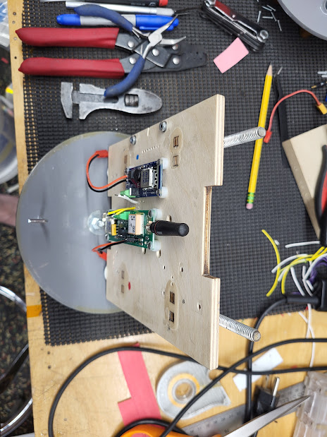
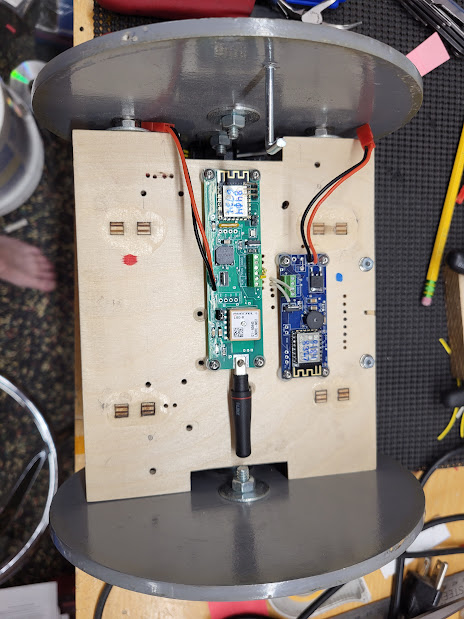
I'm thinking about a short-fat (Big Daddy in BT-80) rocket with a 29mm motor that's almost as long as the rocket. Total length of the rocket is about 16 inches and a 29/360 case is close to 13 inches. The plan for recovery is rear-ejecting the guts as a spool. Obviously, it needs tracking of some kind. I have a couple Eggfinder Minis, so that's the obvious choice. I'd like to mount the tracker down lower in the stack, keeping it out of the nose and out of the ejection blast zone (trying to make this work with motor eject). But that puts it alongside an aluminum case. How badly is that likely to fubar my transmission?
The Big Daddy being short and fat, from memory, could be very sensitive to additional masses, depending on where they are located along the central axis. So, be careful with its stability.
On the RF question, the installation of a tracker adjacent a 13" 29mm motor case is an interesting case study. With the tracker's monopole antenna probably 10-15mm from the Aluminium case (a passive radiator), there will be a detuning of the antenna's resonant frequency and efficiency reduction in the radiated power due to the effects on antenna impedance. Additionally, the presence of a large metal cylinder this close to the antenna will also distort the radiation pattern. To get an idea of what the radiation pattern might look like, I ran a few simulations.
In the attached PDF, Figure 1 displays the typical radiation pattern of a monopole in free space. On the left is the azimuthal pattern, looking down the rocket's main axis; on the right is the elevation pattern, looking from the side of the rocket. In the following figures, the monopole antenna (the short vertical element at the left) is installed about 10-15mm to the side of the motor case (the long vertical element on the left). The monopole is initially installed near the centre of the motor case; then near the bottom of the case; finally, near the top of the case.
If you look at the pattern pairs in Figures 2, 3 and 4, you will see that the azimuthal and elevation radiation patterns vary quite significantly, depending on where the monopole is located with respect to the motor case element. Additionally, you can see the respective 3D radiation patterns in Figures 5, 6, 7 and 8. Although this is a very basic analysis, you can see that the radiation pattern is distorted due to the presence of the motor case. If you must install the tracker beside the motor case, then try to install it where the antenna is around the midpoint along the length of the case. At least the resulting radiation pattern will be closer to symmetrical in the upper and lower elevations (see Radiation Pattern 2b).
The bottom line here, though, is the link budget. The link budget accounts for transmitter power, losses around the Tx/Rx end, antenna gains (Tx and Rx), path loss between Tx and Rx, etc. If there is a significant loss in Tx antenna gain due to a sub-optimal installation, then it could effect the received signal. Using a high gain Rx antenna (Yagi) can mitigate this loss. Typically, link budgets are pretty robust and line-of-sight reception in flight is generally very reliable. It's when the rocket has landed that this can make a big difference. However, even in flight, a rocket's orientation with respect to the Rx antenna might be such that you have reduced power from the Tx due to the radiation pattern distortions. Luckily (?), rockets typically rotate about their central axis, so this effect is mitigated to some extent.
What ever you choose to do with the tracker, it'll probably work just fine under ideal circumstances, but it might not be optimal. You might need to carefully consider where you place the tracker and its battery. The location of these along an offset main axis will effect your stability.
Good luck.