Eggfinder Quasar Antenna Proximity to Av-Bay Metal

The Rocketry Forum

Help Support The Rocketry Forum:

This site may earn a commission from merchant affiliate links, including eBay, Amazon, and others.

wonderboy

Well-Known Member
TRF Supporter
Joined
Jun 11, 2012
Messages
312
Reaction score
336
Location
S.E. Michigan
I'm installing my new Eggfinder Quasar and Quantum in the 7.5" LOC av-bay on my Doorknob. I was paying attention to the two long threaded rods that secure the av-bay bulkheads together and located the Quasar centered between the two (as far as I could from them). The thing I overlooked was the u-bolt that is in the center of the bulkhead that accepts the shock cord.

How bad is something at the tip of the antenna? I think from what I've read that the antenna signal propagates from the sides of the antenna, I'm hoping that the u-bolt at the tip of the antenna won't degrade things too much.

Should I find another arrangement for this, or should I be ok?

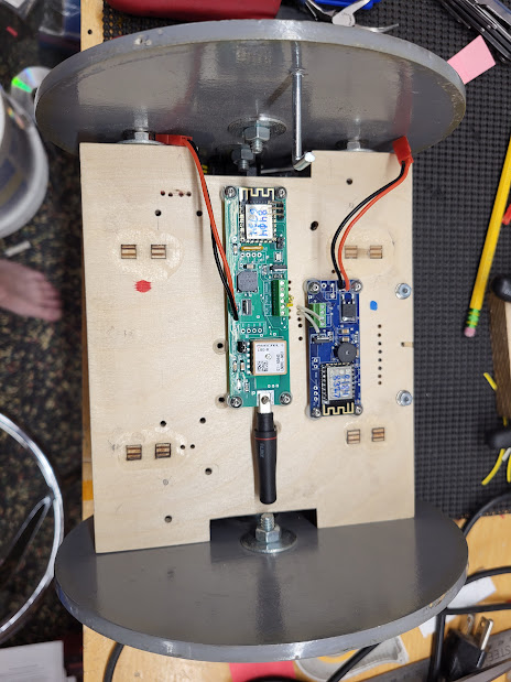
Here is the antenna relative to the threaded rods:
AIL4fc_InzM_xqmJgndCBPBtZRreItWM_8zzh-PWY68z0Akx6SLFmFNZaKqV_zSRFRrG10lgURxUWFZC_xAwll44jNbAPg8I2WPOOCyir1ZC_4iqvxUGtH1ZufxCLiebdDNw8xT5-8-A7tQmHU2Pq6aCcJxIkP9hwqfF275d1Uus4siQmkMcj8gdkP8XA2I23DW8XYOqm9tumAs75vtd214fX7EEuiPWGVYpXKZe-Ot6es1rVyxD5WMVp9_1WyY6PhXbi-3udLaxkuK6bnzi9_Yn1QVwvQpLyB76-Fwmk63-c8LDmqBvdOhhsjGTbpFhPC9QrTdkxVbzSP4lp-U3MwQl4EZj6bVAde3RConYMGtSxsp4msiYPrxp7Avq-5TSSo-WU9RvT6IdKyyT2fekIYSbqn7ENnUyKh5kkH8f6tzbHGGOaAZLbluNSjKRBKn9xxEyzQWA8t_fQEGChXmSdnPv9hgk0Z_o0n6xNrBqRjCap06wA5qKNVCMDcVAk_uqH0pVzMECYw-9CVfeePuYnitaMa38IfxvxR3mmfODrL435c63_mxUPfksNJ0UWN0XboVEII2GhrxV53GMpwsXmA4IZAz4zeuypdEhiIfdUQtW3rAqFdw13_YNn1Gr5P4Hcft4IKBAuVRYYkVlFHH8qrjYDFGQxgBapFxAWeHa_DXUxsAKsQF8RrOufNcci9hLEF2TGdBusJlNtP6oSv4oT_HJkSpT2eEy7XGhMuBr7uEuWC3TaVsx3cLi5lstmCVu8CFIDX8q6DkhvUFZp3C2238txwdUxLEKptCgW859RGkM15U3I7299YjyE1M8enVRbGkxUab83SHPitGl1emDEOETCrO2UwxA6OBGM0NaElau0xqJFic6rAjC_-xYjEW4gGPGbx8W1tUJDyvlzs7pqDQxYmM=w464-h619-s-no


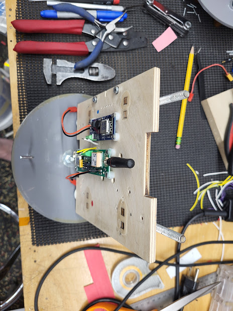
Here is the antenna relative to the u-bolt on the bulkhead:
AIL4fc9l9A3sZQlryp-l1zwfs3uV1nGSgJMEWL5LMddt1-xOITo6UofR9ZI2jvXgjkK8_bZJ-1wyumKPX-vQqYgZMAAVxYWsy1lF48V42mbJQR8RifU82aS010F3M-dVLnfLRibjsR96MYsFzErkdOGk54eUvi7ZI5LzrRitT8vgr3VRCaS3d6pApD_xpvjY5TMmM7SUGbBqzwoyd_-Q2ZtaS3IxMXBiurhroX1bs1Lm9RXb6jV6rGxzp-v3rQett6pypOPMKnoQmnJY5PasazlqOU9Rbbj1JiPkeAEacUp3a09CDYpggXaZIEaWSUxJK2yTSYdqY9uzu8Ckejpn99G4_Q8PfwBI6EgJ1SdBxGN--cFAMigWs3rorRZCoJ5BQftrvvYOsp1RViDq3KiKP_eLp_XKAG6VhBbq4nGt8OwHE0B2_qONN-zf0p3Rv4FlC8Rma9jafraIHm-qdFb4l_fVEN_e8J0lfSK-veUrPyVlNLUEx_dtg76zk1eMC4N3oMULeqL4_wXPZDbmTE8Lq5zYzw8FdkK8k2KakUkQUHoZA8yjXCyaT5ZTuhRmC4fOvK2xt24MfXum6ZaFz7jtqX0cW3rIPM5Z6Tqp3Jq8WJ-das_jeIXBwi6PwMaDEhqO1SJjc1dpJp-ku4kKtoFEKyqluKcdQ-joOkflukh85Ho7SYOW4P7HVB6s9G0-b51ZTo9Z1-6OZyjXoDUti8Lxc2mBr6jc3IQpEpYVT7T4ixb6Ftcb3dNLOCCqiZJ1LjoYv9CSuS8zAD9-3Hro5nUCgzVgx6mkkbyILGXIWz5dI9AGk-QBExHYlHGb9Id5TM4eTrEf69E7tbyDK4zzRq6rw3rEEU57oZcTiHFjai5N2LpJGhaIDm5J7uSi8w9hjyaWG2FrQNuxV4DYWgiqGCy7xQXeos0=w464-h619-s-no
 
The far field radiation pattern for a monopole antenna will exhibit nulls along the main axis. In your case, where the metal bolts are on this same axis, the effects are harder to predict, unless you use a decent EM field plotter. In my experience in lab measurements, there will be a minimal affect on the radiation pattern, perhaps more on antenna impedance due to the close proximity of the bolts. However, if you’re only expecting 2500’ for your flight, then you’ll probably not have any issues at all.

The other potential issue is with the metal allthread rods running parallel with the antenna. In your case the rods appear to be 2”-3” away from the antenna. Even at that distance, they will affect your radiation pattern, because they become passive radiators of the RF from your antenna. In flight up to 2500’ you probably wouldn’t notice anything because your link budget would provide more than adequate margin. It’s when the rocket lands that is more important because if there is a radiation pattern anomaly, then that might affect the chances locating the rocket, unless you were able to get a good fix just prior to landing. Again, if your link budget is good, then I agree with Cris that you shouldn’t have any issues.

Just out of curiosity, what are those bulkheads made of? Painted fibreglass or plywood?
 
Last edited:
Thanks for the explanation Voyager1!

The bulkheads are just plywood. I painted them just to make cleanup a bit easier.

I've been thinking about how to eliminate the all-thread rods that run through the av-bay, but I'm just not sure what non-metallic (or maybe more correctly specified as "RF immune") concept I can use to keep the av-bay lids together. The key is that these rods carry the recovery harness loads through the avbay. I found nylon and fiberglass threaded rods, but I can't imagine them being able to handle the loads.

Like has been stated, for now this rocket is only going a few thousand feet (visible the entire flight) and I expect I'll be able to get decent GPS info on the way down under chute. So I'm probably not going to have to worry... but I'll keep on thinking about how to eliminate those threaded rods.

Thanks again for the info!

Have you considered just buttoning up the avionics bay, turn on the GPS, and have someone drive
the bay about a mile down the road. That's how I test trackers that are mounted in the av-bay.

I live on the edge of town where it transitions from suburbs to rural. Plenty of 2-lane and 4-lane
county roads to give it a good test - with a rise or two between the two points.

All trackers do well with clear blue skies - even with threaded rods around them. I think the threaded
rod concern is only an issue once your rocket is down in the weeds. No telling which way the bay will
be resting. But a 1-mile test will give you some good info for addressing your concern.
 
All trackers do well with clear blue skies - even with threaded rods around them. I think the threaded rod concern is only an issue once your rocket is down in the weeds. No telling which way the bay will be resting. But a 1-mile test will give you some good info for addressing your concern.
Yep! If in doubt, try it out. A ground test when you, or someone else, knows where the rocket is, is a good way to confirm link reliability.
 
I vaguely remember that the ground distance will be 4X in the air. That's for RC planes and high up unobstructed rockets would be better. But the point you want the telemetry gps is just before it lands so back to the 4:1 Testing to 1 mile on the ground should give you a GPS location back on telemetry up to roughly 4 miles just before it lands---- ish. 2 miles on the ground would get you the GPS position up to 8 miles away-----ish
 
Thanks for the explanation Voyager1!

The bulkheads are just plywood. I painted them just to make cleanup a bit easier.

I've been thinking about how to eliminate the all-thread rods that run through the av-bay, but I'm just not sure what non-metallic (or maybe more correctly specified as "RF immune") concept I can use to keep the av-bay lids together. The key is that these rods carry the recovery harness loads through the avbay. I found nylon and fiberglass threaded rods, but I can't imagine them being able to handle the loads.

Like has been stated, for now this rocket is only going a few thousand feet (visible the entire flight) and I expect I'll be able to get decent GPS info on the way down under chute. So I'm probably not going to have to worry... but I'll keep on thinking about how to eliminate those threaded rods.

Thanks again for the info!
In all my avbays up to 54mm I use 6mm (~1/4”) Nylon allthread to keep the weight down. Larger avbays (75mm and 98mm) I use metal allthread. However, none of my avbays have RF modules installed in them. All my RF modules (telemetry and GPS) go in the nosecone. If I want to optimise the radiation/reception pattern, that’s where it goes.

I can understand that in some cases this might not be possible, but if it is, then why not! If there was a need for me to install an RF module in the avbay, then I would at least try to mount the antenna on the outside of the forward avbay bulkplate. That itself can be a challenge in some cases.
 
I vaguely remember that the ground distance will be 4X in the air. That's for RC planes and high up unobstructed rockets would be better. But the point you want the telemetry gps is just before it lands so back to the 4:1 Testing to 1 mile on the ground should give you a GPS location back on telemetry up to roughly 4 miles just before it lands---- ish. 2 miles on the ground would get you the GPS position up to 8 miles away-----ish

That calculation is only relevant if the base station is downwind of the rocket's location . . . .


(just messing with ya')
 
The only point you really need the location is when it lands away from you. The other times are useful. But not critical or expensive.

What's wind direction got to do with it? 😁
 
I'm thinking about a short-fat (Big Daddy in BT-80) rocket with a 29mm motor that's almost as long as the rocket. Total length of the rocket is about 16 inches and a 29/360 case is close to 13 inches. The plan for recovery is rear-ejecting the guts as a spool. Obviously, it needs tracking of some kind. I have a couple Eggfinder Minis, so that's the obvious choice. I'd like to mount the tracker down lower in the stack, keeping it out of the nose and out of the ejection blast zone (trying to make this work with motor eject). But that puts it alongside an aluminum case. How badly is that likely to fubar my transmission?
 
I'm thinking about a short-fat (Big Daddy in BT-80) rocket with a 29mm motor that's almost as long as the rocket. Total length of the rocket is about 16 inches and a 29/360 case is close to 13 inches. The plan for recovery is rear-ejecting the guts as a spool. Obviously, it needs tracking of some kind. I have a couple Eggfinder Minis, so that's the obvious choice. I'd like to mount the tracker down lower in the stack, keeping it out of the nose and out of the ejection blast zone (trying to make this work with motor eject). But that puts it alongside an aluminum case. How badly is that likely to fubar my transmission?
The Big Daddy being short and fat, from memory, could be very sensitive to additional masses, depending on where they are located along the central axis. So, be careful with its stability.

On the RF question, the installation of a tracker adjacent a 13" 29mm motor case is an interesting case study. With the tracker's monopole antenna probably 10-15mm from the Aluminium case (a passive radiator), there will be a detuning of the antenna's resonant frequency and efficiency reduction in the radiated power due to the effects on antenna impedance. Additionally, the presence of a large metal cylinder this close to the antenna will also distort the radiation pattern. To get an idea of what the radiation pattern might look like, I ran a few simulations.

In the attached PDF, Figure 1 displays the typical radiation pattern of a monopole in free space. On the left is the azimuthal pattern, looking down the rocket's main axis; on the right is the elevation pattern, looking from the side of the rocket. In the following figures, the monopole antenna (the short vertical element at the left) is installed about 10-15mm to the side of the motor case (the long vertical element on the left). The monopole is initially installed near the centre of the motor case; then near the bottom of the case; finally, near the top of the case.

If you look at the pattern pairs in Figures 2, 3 and 4, you will see that the azimuthal and elevation radiation patterns vary quite significantly, depending on where the monopole is located with respect to the motor case element. Additionally, you can see the respective 3D radiation patterns in Figures 5, 6, 7 and 8. Although this is a very basic analysis, you can see that the radiation pattern is distorted due to the presence of the motor case. If you must install the tracker beside the motor case, then try to install it where the antenna is around the midpoint along the length of the case. At least the resulting radiation pattern will be closer to symmetrical in the upper and lower elevations (see Radiation Pattern 2b).

The bottom line here, though, is the link budget. The link budget accounts for transmitter power, losses around the Tx/Rx end, antenna gains (Tx and Rx), path loss between Tx and Rx, etc. If there is a significant loss in Tx antenna gain due to a sub-optimal installation, then it could effect the received signal. Using a high gain Rx antenna (Yagi) can mitigate this loss. Typically, link budgets are pretty robust and line-of-sight reception in flight is generally very reliable. It's when the rocket has landed that this can make a big difference. However, even in flight, a rocket's orientation with respect to the Rx antenna might be such that you have reduced power from the Tx due to the radiation pattern distortions. Luckily (?), rockets typically rotate about their central axis, so this effect is mitigated to some extent.

What ever you choose to do with the tracker, it'll probably work just fine under ideal circumstances, but it might not be optimal. You might need to carefully consider where you place the tracker and its battery. The location of these along an offset main axis will effect your stability.

Good luck.
 

Attachments

  • Monopole Radiation Patterns.pdf
    370.6 KB · Views: 0
Last edited:
As Voyager1 noted. The length of your motor will have negative impacts on your CG location. Because the CG of the motor is itself in front of the CP, as it burns, the CG will move backward. So make sure you know where your CG is at all times and that it stays a caliber or 10% (depending on your club/arganisations/RSO policy) of the length of the rocket, in front of the CP.
Good luck with the flight.
Also interesting is that the motor's designated length doesn't match the actual length. In the 29mm Aerotech series, some are longer than the designation and some are shorter, like the 29/360.

https://www.rocketryforum.com/threads/aerotech-case-dimensions-18mm-to-75mm.27431/post-243785
 
Back
Top