

xenon
Well-Known Member
- Joined
- Jan 25, 2009
- Messages
- 701
- Reaction score
- 0
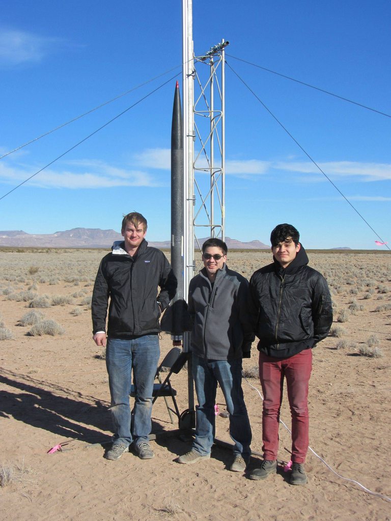
Team Last Minute Rocketry travelled to Tripoli Las Cruces the weekend of December 29th for a final attempt at CTIs N5800 Challenge. As our group name implies, we push things to the last minute, and this project was no exception. Construction started December 21 and was mostly finished by the 24th. A last minute 15 hour session on December 28-29 finished up the rocket in time for a 10:15 am launch at FLAREs West Mesa, Las Cruces launch site.
Im going to briefly cover the construction and flight in the same thread, with a few pictures.
Details on the rocket are as follows:
Pad weight: 43.2 lb
Dry weight: 10.5 lb
Max external diameter: 4.055
Length: 84.5
Expected Altitude: 51,700
Expected Max Velocity: 3,795 ft/s (Mach 3.55)
Burnout Altitude: 7,800
Launch system: 2x 10¹⁰ buttons, 10 rail
Subsonic (launch) stability margin: 1.91 calibers
Burnout stability margin: 2.43 calibers
The rocket was basically all composite and mostly carbon. From the top down:
The nose cone was a Performance Rocketry 4 FWFG nose cone with red anodized aluminum tip. The bulkplate holding the #10 screw that holds the tip in was glued in place with 5 minute epoxy. The area above this bulkhead was filled with ProLine 4500, and the tip was screwed on. Excess resin that squeezed out was cleaned up with a rag before it cured. The provided coupler tube/shoulder was glassed internally with 2 wide strips of 10oz glass. The coupler was then glued into the nosecone with 5 minute epoxy then the coupler-nose joint was glassed in a similar manner. The forward part of the nose was filled with Evercoat 2 part foam. A bulkhead with a piece of ⅜ threaded rod bolted to it and a large number of holes to allow foam flow was glued into the nosecone with 5 minute epoxy about 10 forward of the base of the nosecone-coupler joint. More foam was poured on top of this until the fiberglass from the nosecone-coupler joint was reached.
The electronics were mounted on a pair of ¼ plywood boards that were attached to a ~3.8 bulkhead. These would slide onto the threaded rod in the nose cone. The goal was to keep all of the electronics forward of the nose-tube joint; however, they ended up extending about 1 below that. Electronics consisted of the following:
-Beeline 70cm High Power GPS with Ublox 6 chip configured to transmit every 5 seconds on the 2 second time slot and store every second. A featherweight magnetic switch was used to power this.
-Beeline 70cm Normal GPS with Ublox 6 chip configured to transmit every 5 seconds on the 0 second time slot on the same frequency as the above one, and store every second. A featherweight magnetic switch was used to power this as well.
-Raven 3 configured to deploy at normal barometric apogee (C02), baro apogee + 3 (BP charge), 15k AGL (BP in drogue bay) and 2,000 (main).
-Stratologger configured for baro apogee and 700 main.
The avionics bay was vented aft into the main parachute bay to avoid drilling holes into the nose or near the nose-tube transition (more for structural than venting purposes). All of the avionics were powered by magnetic switches, also to avoid holes.
The upper tube consisted of a 30 section of 4 LOC tubing stripped down to a minimal amount of layers. Two layers of Soller Composites sleeve using Aeropoxy was applied to the tube. A spare motor case was used as a mandrel to keep the cardboard from deforming during layup. A 3oz layer of fiberglass was also applied as a veil layer. A bulkhead was glued in such that it rested on top of the eye bolt in the top of the motor. A Rouse-Tech CD3 system was installed in this bulkhead with a 16 gram cartridge.
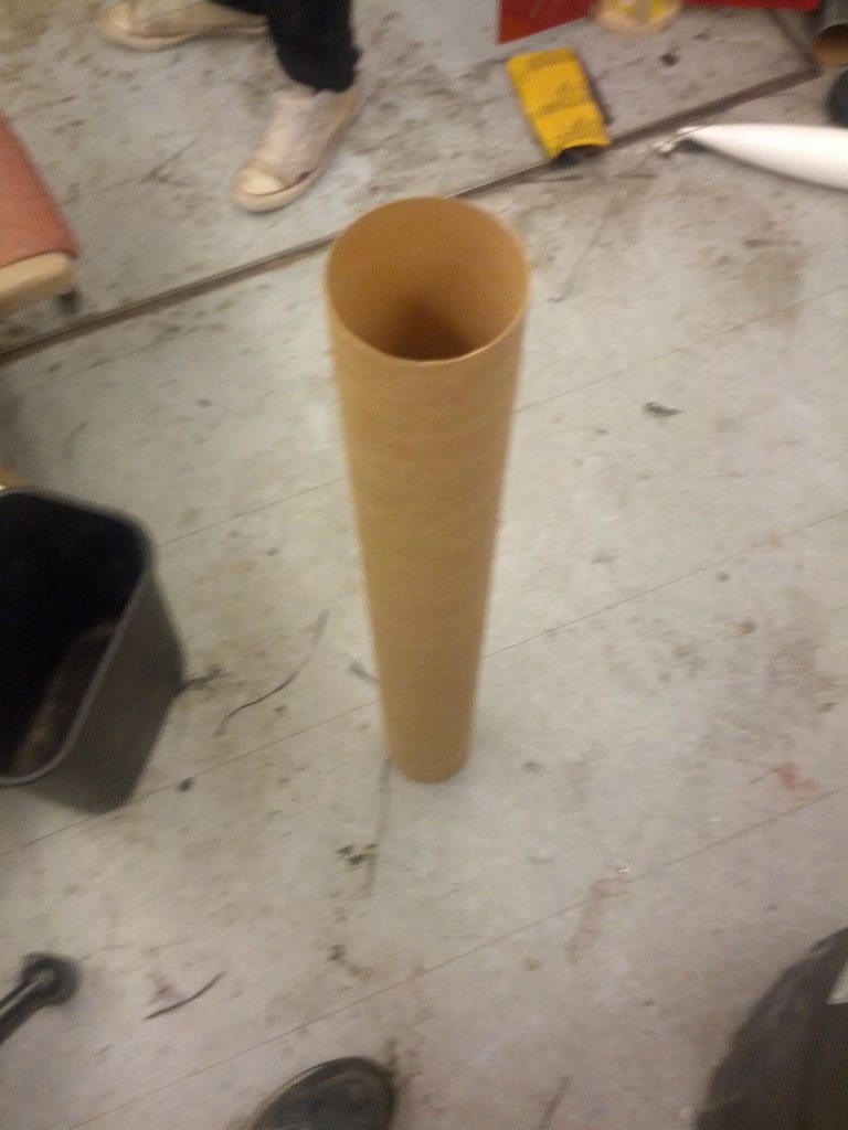
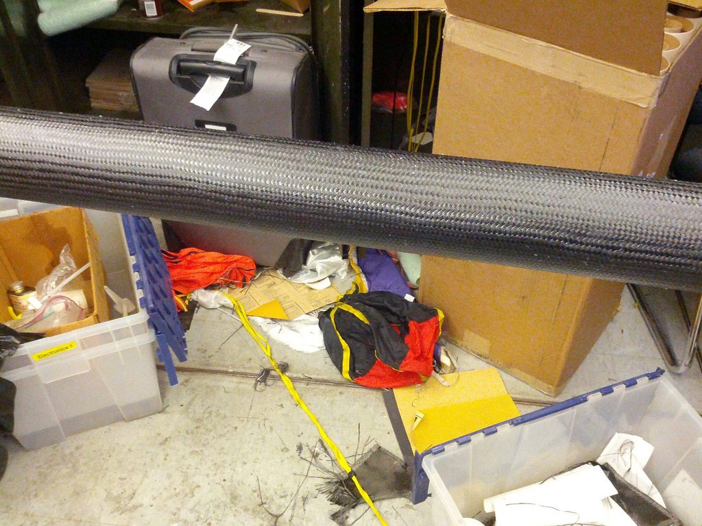
The lower tube was constructed similarly, except with a single layer of Soller sleeve and a single layer of 14oz or so carbon wrapped around it with no veil layer. It was also 30 long.
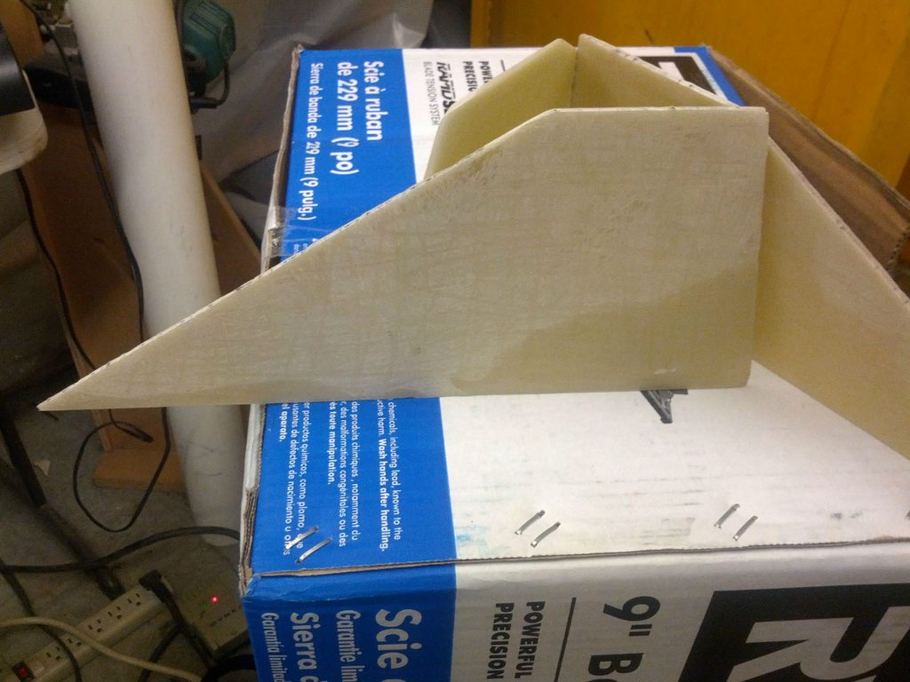
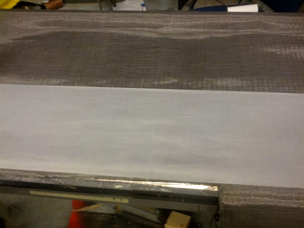
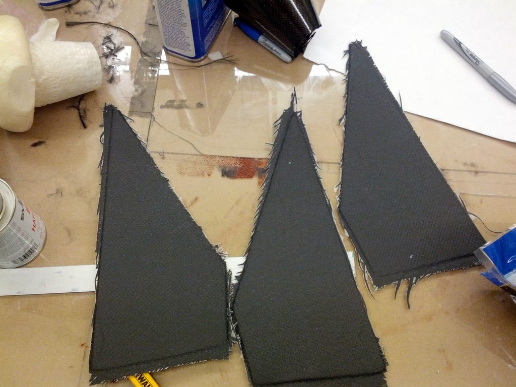
Fins were ⅛ G10 with a 12 root, 4.75 span, 8 sweep and 3 tip cord. They were laminated on each side with 3 layers of 14oz carbon using Aeropoxy, bringing their total thickness to approximately .21. They were tacked to the tube with 5 minute epoxy, filleted with ProLine 4500 and had 4 layers of tip to tip 14oz carbon of increasing length using West 206. Final measurements showed a 1.25 L.E. airfoil length, 1.0 on the T.E, a L.E radius of 0.035 and an average thickness of 0.30. The leading edges back to behind the outermost tip to tip ply were painted with Quick Weld (fast JB weld).
G10 Prepped
Wax paper on the carbon for tracing the profiles
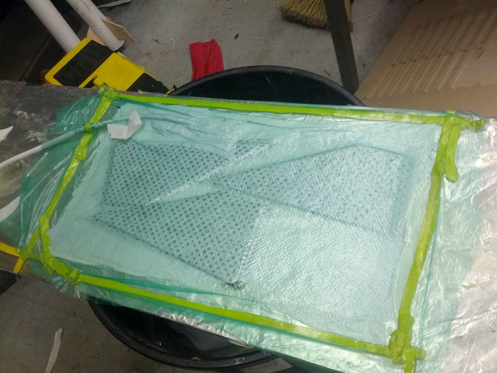
Vacuum Bagged
Fresh out of the bag
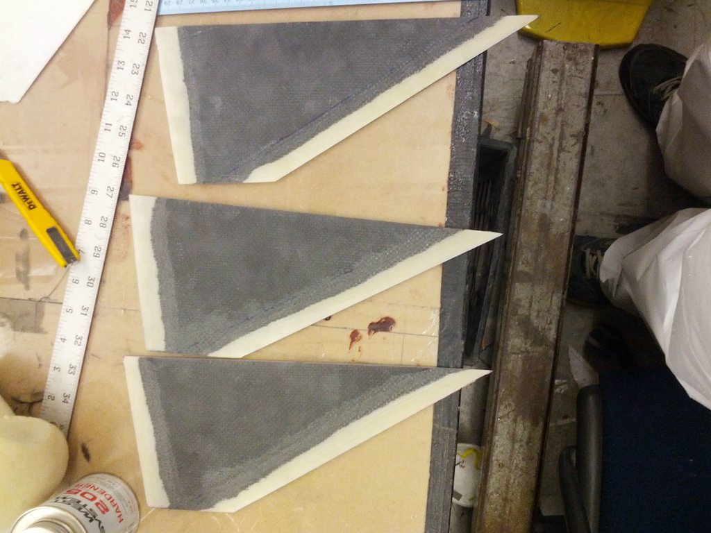
Cleaned up and tapered
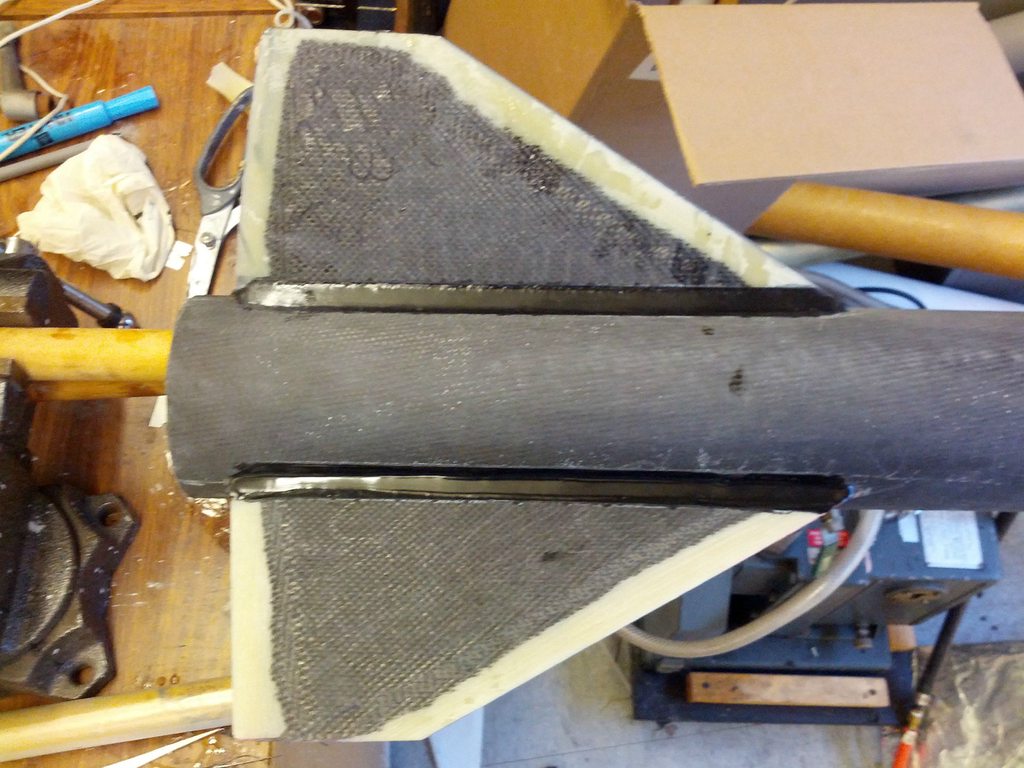
Fillets
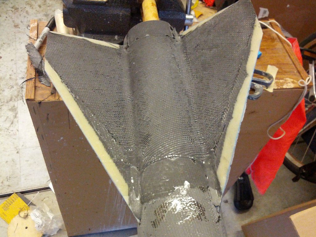
Tip to Tip
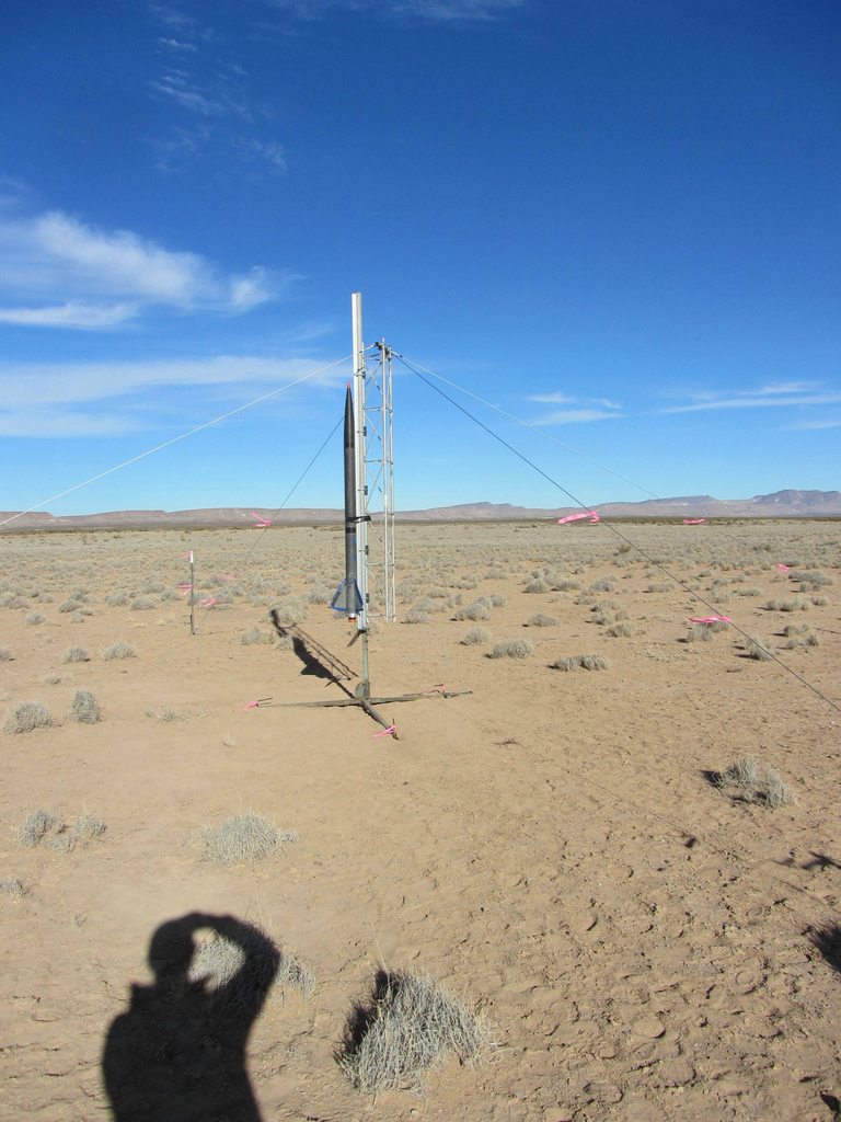
Recovery was drogueless at apogee with a 58 bright orange topflight parachute at 2,000. Lower tube rested (tightly) on the motor case, and the upper tube used the top 20 or so of the motor case as a coupler. This joint was to be separated at apogee, with the nose (using 2x 2-56 shear pins) coming off at 2,000. A 1010 rail button was installed in the upper tube, along with in a waterjetted and sanded aluminum ring that was slid on the aft end of the case. The tailcone that we initially intended to fly was not used due to manufacturing issues (ending with the TSA taking our foam and glue, but not beginning there), and the fact that we were satisfied with the simulated altitude without it. Finally, a 70cm GPS beacon was taped and wired to the forward closure of the motor.
Final on the pad weight was 42.3lb with a stability margin of 1.91 (based off fully loaded CG measurements).
Launch occurred during continuity checks at 10:14:38 Mountain Time, so unfortunately we dont have any pictures or video to show. Data shows a reasonably nominal flight until 2.43 seconds in. An increasing lateral acceleration that peaked at about 1.5gs (23 forward of the CG) began to occur. At 2.67 seconds in going M3.15 (3,400fps) and 4,400 or so (based off simulated data), the nosecone liberated itself from the rest of the rocket by some means. The nosecone decelerated rapidly, pegging both the axial and lateral accelerometers on the Raven simultaneously. The baro sensor reports that it reached an apogee of about 5,400. Total flight time on the nosecone was 62 seconds.
Other notes:
-The fins came off too. We didnt find them or get any pictures of them in flight
-The power wire on the HP GPS was cut on takeoff due to one of the boards shifting
-The GPS receiver antenna on the LP GPS was damaged on takeoff as well
-The transmit antenna on the LP GPS was damaged and stopped transmitting once it hit the ground
-The avionics bulkhead was cracked in half, and somehow managed to take the stratologger with it
-The only pieces we found were as follows:
Lower tube, sans fins, 1750, 323 degrees from the launch site
Lower 20 of upper tube
Nose cone, 1350 due north of the launch site
Nose cone coupler, 2 further out of the nosecone than it had been previously
Motor case
Part of the electrical tape that was holding the Beeline beacon to the motor.
The main parachute was seen drifting off
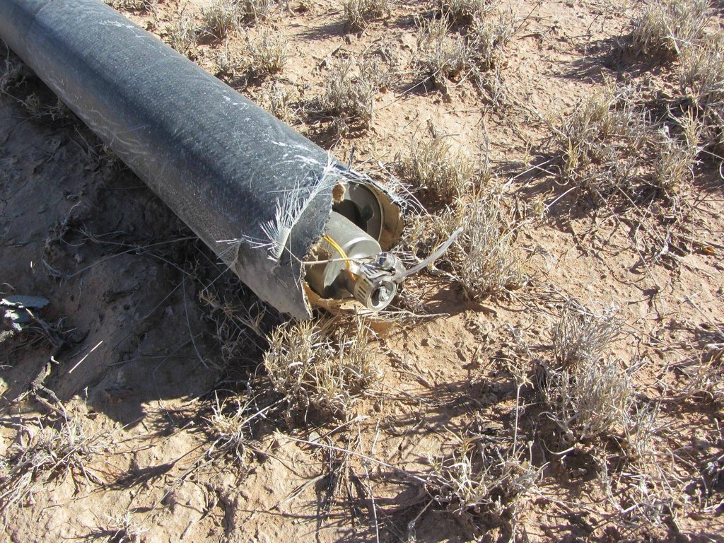
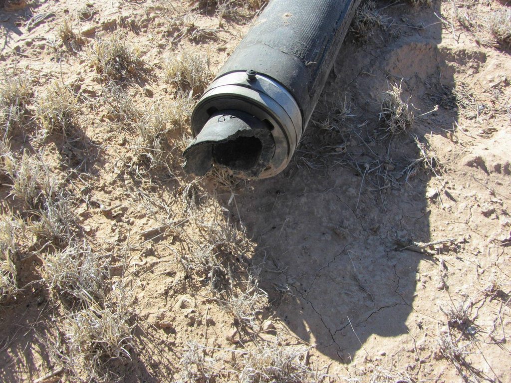
Front of the motor, missing the eye bolt
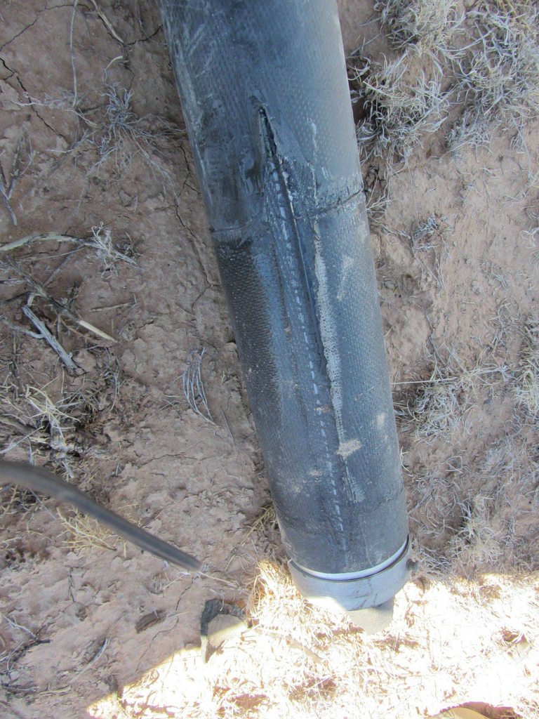
Other end of the motor
Used to be a fin there
Front again
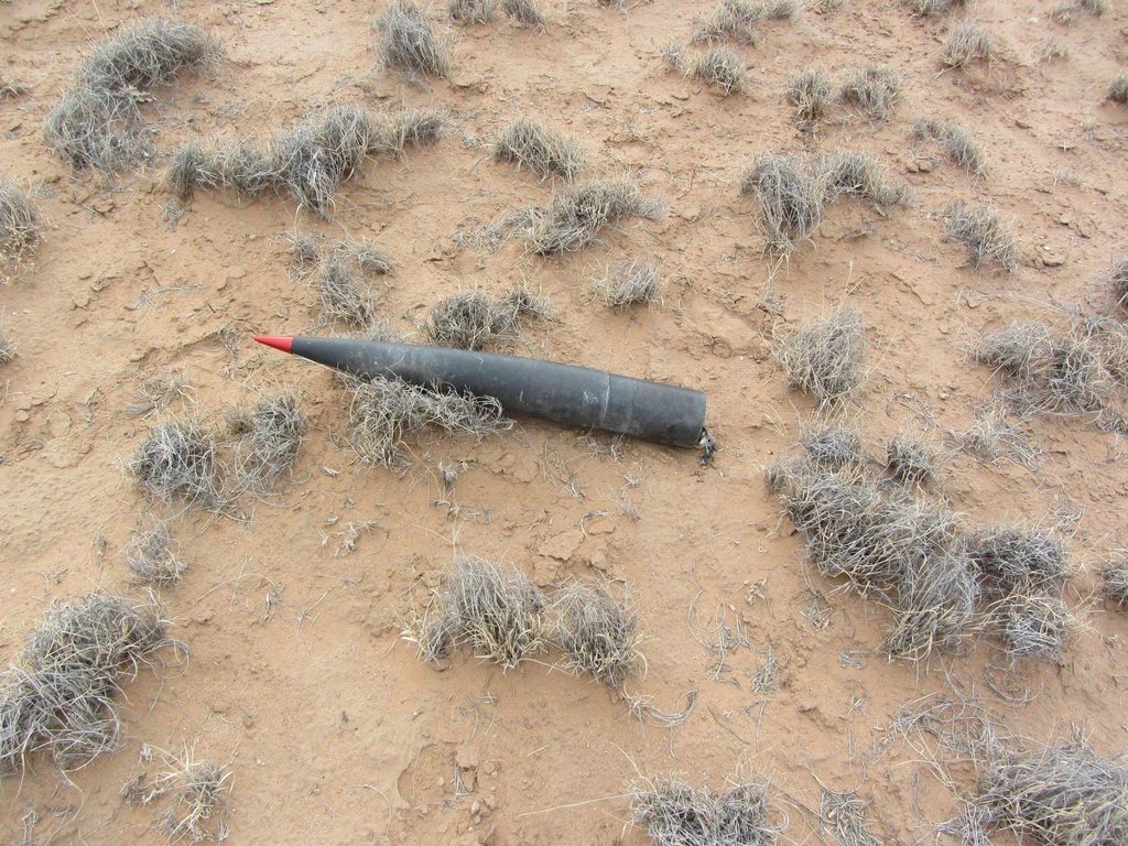
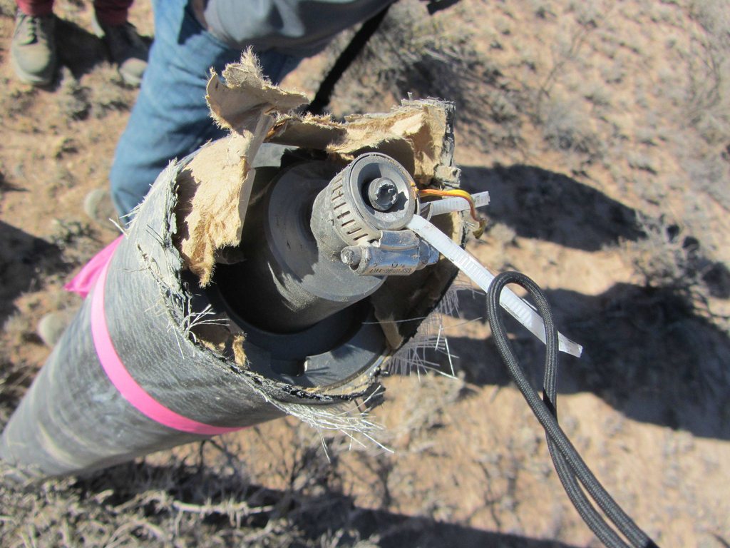
Nose as found
Internals, post flight
So what happened?
It broke.
A couple theories:
-Stratologger blew the drogue charge on the way up (see baro trace on Raven). This is unlikely due to the fact that the upper tube was still on the motor case when we got it back. The small dip in pressure just before breakup occurs while the slope of the baro pressure is approximately 2,300ft/sec. This implies that even if the stratologger had a clue what was going on and detected launch (who knows if it did or not), that it would have locked out due to the velocity. Also, the CO2 charge isnt much of a match against the 300lb of drag on the vehicle at that point
-A fin came off. Sure. Theres not much evidence for or against this other than it did happen at some point.
-The upper tube broke. See previous bullet point.
-Wind shear. Data from El Paso that morning supports a 10 knot shift in speed and 150 degree direction shift at the altitude where the breakup occurred. Observations at the launch site support stronger winds by the time launch occured. Rocksim simulations using 0 mph ground winds and similar speed (12mph) upper winds could result in oscillations that would create a lateral acceleration of similar size to that seen in the accelerometer data. This oscillation would nominally damp itself out, but for whatever reason (structural failure?) it didnt.
-Aliens. Wouldnt surprise me. We were in New Mexico after all.
Thanks to the New Mexico and Texas folks for helping with a place to finish up constrep (new term for construction/prep) and a great launch site and lunch.
View attachment Black Magic.FIPa
Im going to briefly cover the construction and flight in the same thread, with a few pictures.
Details on the rocket are as follows:
Pad weight: 43.2 lb
Dry weight: 10.5 lb
Max external diameter: 4.055
Length: 84.5
Expected Altitude: 51,700
Expected Max Velocity: 3,795 ft/s (Mach 3.55)
Burnout Altitude: 7,800
Launch system: 2x 10¹⁰ buttons, 10 rail
Subsonic (launch) stability margin: 1.91 calibers
Burnout stability margin: 2.43 calibers
The rocket was basically all composite and mostly carbon. From the top down:
The nose cone was a Performance Rocketry 4 FWFG nose cone with red anodized aluminum tip. The bulkplate holding the #10 screw that holds the tip in was glued in place with 5 minute epoxy. The area above this bulkhead was filled with ProLine 4500, and the tip was screwed on. Excess resin that squeezed out was cleaned up with a rag before it cured. The provided coupler tube/shoulder was glassed internally with 2 wide strips of 10oz glass. The coupler was then glued into the nosecone with 5 minute epoxy then the coupler-nose joint was glassed in a similar manner. The forward part of the nose was filled with Evercoat 2 part foam. A bulkhead with a piece of ⅜ threaded rod bolted to it and a large number of holes to allow foam flow was glued into the nosecone with 5 minute epoxy about 10 forward of the base of the nosecone-coupler joint. More foam was poured on top of this until the fiberglass from the nosecone-coupler joint was reached.
The electronics were mounted on a pair of ¼ plywood boards that were attached to a ~3.8 bulkhead. These would slide onto the threaded rod in the nose cone. The goal was to keep all of the electronics forward of the nose-tube joint; however, they ended up extending about 1 below that. Electronics consisted of the following:
-Beeline 70cm High Power GPS with Ublox 6 chip configured to transmit every 5 seconds on the 2 second time slot and store every second. A featherweight magnetic switch was used to power this.
-Beeline 70cm Normal GPS with Ublox 6 chip configured to transmit every 5 seconds on the 0 second time slot on the same frequency as the above one, and store every second. A featherweight magnetic switch was used to power this as well.
-Raven 3 configured to deploy at normal barometric apogee (C02), baro apogee + 3 (BP charge), 15k AGL (BP in drogue bay) and 2,000 (main).
-Stratologger configured for baro apogee and 700 main.
The avionics bay was vented aft into the main parachute bay to avoid drilling holes into the nose or near the nose-tube transition (more for structural than venting purposes). All of the avionics were powered by magnetic switches, also to avoid holes.
The upper tube consisted of a 30 section of 4 LOC tubing stripped down to a minimal amount of layers. Two layers of Soller Composites sleeve using Aeropoxy was applied to the tube. A spare motor case was used as a mandrel to keep the cardboard from deforming during layup. A 3oz layer of fiberglass was also applied as a veil layer. A bulkhead was glued in such that it rested on top of the eye bolt in the top of the motor. A Rouse-Tech CD3 system was installed in this bulkhead with a 16 gram cartridge.
The lower tube was constructed similarly, except with a single layer of Soller sleeve and a single layer of 14oz or so carbon wrapped around it with no veil layer. It was also 30 long.
Fins were ⅛ G10 with a 12 root, 4.75 span, 8 sweep and 3 tip cord. They were laminated on each side with 3 layers of 14oz carbon using Aeropoxy, bringing their total thickness to approximately .21. They were tacked to the tube with 5 minute epoxy, filleted with ProLine 4500 and had 4 layers of tip to tip 14oz carbon of increasing length using West 206. Final measurements showed a 1.25 L.E. airfoil length, 1.0 on the T.E, a L.E radius of 0.035 and an average thickness of 0.30. The leading edges back to behind the outermost tip to tip ply were painted with Quick Weld (fast JB weld).
G10 Prepped
Wax paper on the carbon for tracing the profiles
Vacuum Bagged
Fresh out of the bag
Cleaned up and tapered
Fillets
Tip to Tip
Recovery was drogueless at apogee with a 58 bright orange topflight parachute at 2,000. Lower tube rested (tightly) on the motor case, and the upper tube used the top 20 or so of the motor case as a coupler. This joint was to be separated at apogee, with the nose (using 2x 2-56 shear pins) coming off at 2,000. A 1010 rail button was installed in the upper tube, along with in a waterjetted and sanded aluminum ring that was slid on the aft end of the case. The tailcone that we initially intended to fly was not used due to manufacturing issues (ending with the TSA taking our foam and glue, but not beginning there), and the fact that we were satisfied with the simulated altitude without it. Finally, a 70cm GPS beacon was taped and wired to the forward closure of the motor.
Final on the pad weight was 42.3lb with a stability margin of 1.91 (based off fully loaded CG measurements).
Launch occurred during continuity checks at 10:14:38 Mountain Time, so unfortunately we dont have any pictures or video to show. Data shows a reasonably nominal flight until 2.43 seconds in. An increasing lateral acceleration that peaked at about 1.5gs (23 forward of the CG) began to occur. At 2.67 seconds in going M3.15 (3,400fps) and 4,400 or so (based off simulated data), the nosecone liberated itself from the rest of the rocket by some means. The nosecone decelerated rapidly, pegging both the axial and lateral accelerometers on the Raven simultaneously. The baro sensor reports that it reached an apogee of about 5,400. Total flight time on the nosecone was 62 seconds.
Other notes:
-The fins came off too. We didnt find them or get any pictures of them in flight
-The power wire on the HP GPS was cut on takeoff due to one of the boards shifting
-The GPS receiver antenna on the LP GPS was damaged on takeoff as well
-The transmit antenna on the LP GPS was damaged and stopped transmitting once it hit the ground
-The avionics bulkhead was cracked in half, and somehow managed to take the stratologger with it
-The only pieces we found were as follows:
Lower tube, sans fins, 1750, 323 degrees from the launch site
Lower 20 of upper tube
Nose cone, 1350 due north of the launch site
Nose cone coupler, 2 further out of the nosecone than it had been previously
Motor case
Part of the electrical tape that was holding the Beeline beacon to the motor.
The main parachute was seen drifting off
Front of the motor, missing the eye bolt
Other end of the motor
Used to be a fin there
Front again
Nose as found
Internals, post flight
So what happened?
It broke.
A couple theories:
-Stratologger blew the drogue charge on the way up (see baro trace on Raven). This is unlikely due to the fact that the upper tube was still on the motor case when we got it back. The small dip in pressure just before breakup occurs while the slope of the baro pressure is approximately 2,300ft/sec. This implies that even if the stratologger had a clue what was going on and detected launch (who knows if it did or not), that it would have locked out due to the velocity. Also, the CO2 charge isnt much of a match against the 300lb of drag on the vehicle at that point
-A fin came off. Sure. Theres not much evidence for or against this other than it did happen at some point.
-The upper tube broke. See previous bullet point.
-Wind shear. Data from El Paso that morning supports a 10 knot shift in speed and 150 degree direction shift at the altitude where the breakup occurred. Observations at the launch site support stronger winds by the time launch occured. Rocksim simulations using 0 mph ground winds and similar speed (12mph) upper winds could result in oscillations that would create a lateral acceleration of similar size to that seen in the accelerometer data. This oscillation would nominally damp itself out, but for whatever reason (structural failure?) it didnt.
-Aliens. Wouldnt surprise me. We were in New Mexico after all.
Thanks to the New Mexico and Texas folks for helping with a place to finish up constrep (new term for construction/prep) and a great launch site and lunch.
View attachment Black Magic.FIPa
Last edited:
")