[Acquisition] Flying Case 38 - CTI J150MY

The Rocketry Forum

Help Support The Rocketry Forum:

This site may earn a commission from merchant affiliate links, including eBay, Amazon, and others.

A5tr0 An0n

Well-Known Member
Joined
Sep 29, 2012
Messages
521
Reaction score
10
Intro:

ac·qui·si·tion: 2. the learning or developing of a skill, habit, or quality.

Since the grounding of my L3 flight due to weather, I have since scratched that vehicle and redesigned the L3. So I noticed that I had some 38mm and 54mm motors in the closet and thought why not scale the design down and burn some. I have helped build two other fin can on motor case designs and have been wanting to acquire more information on them, hence the name. Short of attaching the fins directly to the case, I am looking to see if this is a more efficient design vs a traditional MD design, and if in fact it is, by how much? My assumption says yes but empirical flight data seems like the quickest and easiest method of finding out. I see pros and cons to both methods and before starting to build the bird for the L3, I wish to acquire more information/experience with flying cases. I am also taking this as a chance to prefect the simulation tools. I have noticed that there are more than one ways to design a flying case and all of the ways produce different results, so I can use this to find the best method.

So here is how it is going to go - more or less. I will build a "flying case," and a conventional MD version of the same vehicle. The plan is for them to be identical to one another (except the obvious), and to fly on the same motor. I am starting with the flying case which this thread will cover and will address the conventional MD in a later thread (likewise with the 54s) .


Design:

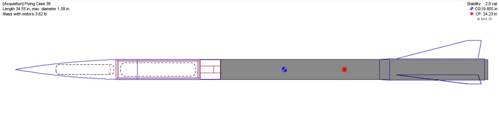
The design thoughts are to reduce the minimum diameter by a little as compared to a conferential minimum diameter… so perhaps a absolute minimum diameter is more appropriate. Furthermore the thoughts were to reduce materials and therefore overall mass, to do so the motor case is being used as the airframe. Thicknesses are down to lowest level I am comfortable with, including nose cone, upper airframe, fin can, couplers, and fins. Finally to build on the previous work of myself and others in the flying case arena. More technical details below.


15619090225_f42da103b3_b.jpg

15432961548_49fcf062d5_b.jpg

15433083877_d577392c9b_b.jpg

14998328004_d2c3d4272c_o.png


Technical Specifications:
14998924383_7d81fd08a9_o.png


**All laminated parts were done so with Proline 4100 Epoxy and structurally epoxied parts used Proline 4500.**


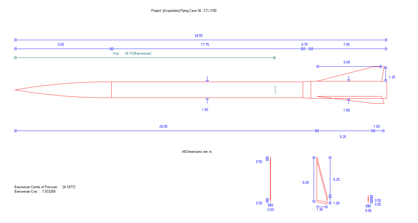
Nose Cone: 6:1 Ogive FWFG Nose Cone measuring 9" Length (6:1 duh), 1.5" Max OD, 1.42" Max ID, 0.04" Wall Thickness, and 0.075lb Mass. No permanently fixed coupler.

Payload: This is the electrical payload bay and also the NC/AF coupler. Hand laid fiberglass (S2) 301.76gsm 8 Harness Satin Weave measuring 6" Length, 1.379" OD, 1.225" ID, 0.077" Wall Thickness, and 0.129lb Mass. The Payload section will be shear pinned to the nose cone and bolted to the UAF/Motor Case Coupler.

Upper Airframe: Seeing as there is no airframe over the motor due to the motor being the airframe, I am calling the tube that couples to the top of the motor the "upper airframe." Hand laid Carbon Fiber 3k 7.5oz measuring 6.09" Length, 1.5" OD, 1.42" ID, 0.04" Wall Thickness, and 0.071lb. Payload tube utilizes standard bulkheads each 0.09" Thick x4 bulkheads, summing 0.032lb Mass.

Motor Adapter / Coupler: Motor Adapter is the Aeropack Delay/Eject-Closure Adapter (motor is plugged); this allows me to attach a bolt to the motor's forward closure, this will be used to secure the motor to the upper airframe. The coupler will rest over the adapter and on the motor case; the upper airframe slides over this and is countersunk into the coupler for security. Through the use of the adapter the closure is bolted into the top of the motor. The Coupler is hand laid Carbon Fiber 12k 19.9oz measuring 1.5" Length, 1.42" OD, 0.5" ID, 0.46" Wall Thickness, and 0.2lb Mass.

Lower Airframe / Motor Case: The lower airframe IS the motor case and is made from anodized 6061 Aluminum, I believe (?) and measures 19.71" Length, 1.5" OD, X" ID, X" Wall Thickness, and Xlb Mass (Loaded Mass = 2.10lb, Burnout Mass = 0.78lb).

Fin Can Transition/Shoulder: The fin can shoulder is a transitional part that transitions the motor case/airframe to the fin can. This should provide a more aerodynamic flow and should prevent a majority of the flow from going underneath the fin can. The should is a hand laid Carbon Fiber 3k 7.5oz that is actually a single part with the fin can, I have just separated the two parts for description purposes. The fin can shoulder is more or less conceal in shape and measures 0.75" Length, 1.5" Fore Diameter, 1.58" Aft Diameter, 0.04" Wall Thickness, and 0.009lb Mass.

Fin Can: The fin can slides over the motor casing until it reaches the motor aft closure, which prevents it from moving aft. The fin can will be friction fit into place, hopefully preventing any rotation of the fin can during flight. The fin can is made from hand laid Carbon Fiber 3k 7.5oz measuring 7" Length, 1.58" OD, 1.5" ID, 0.04" Wall Thickness, and 0.087lb Mass.

Fins: This vehicle utilizes a 3 fin design as opposed to a 4 fin design. The reasons for this is greater dynamic stability is not needed, the tower is designed for 3 fins, easier work, less materials, and possibly less drag. To negate the aforementioned I would need to make the 4 fins smaller, which is not really possible given the span as of now is already very small. The fins are a standard swept back clipped delta; this is my first time incorporating a swept back design. I have been reluctant to use swept back fins in the past for structural concerns, a lesser portion of the fin is supported. However after looking at other successful flights I feel quite confident in the design. The move for swept back fins was for the increase in performance that they are forecasted to bring, however at a trade off in slight overall stability. The fins are made from Quasi-isotropic Twill/Uni blend Carbon Fiber (yes they alternate by 0/90 degrees) and measure 6" Root Chord, 0.5" Tip Chord, 1.35" Span, 5.75" Sweep Length, 76.8 degree Sweep Angle, 0.043lb Mass, and 0.06" Thickness. The fins are located 28.05" from the tip of the nose cone.

Deployment / Recovery: Deployment will be via a cable cutter wrapped around the main parachute (only parachute) that is housed in the nose cone. At apogee the nose cone separates from the coupler/airframe via a Xg BP charge, pulling the wrapped parachute out into the atmosphere. At the designated main altitude (1500ft) the cable wrapping the parachute is sheared and the main unfolds and inflates slowing the vehicle down. Recovery Parachute size TBD.

Electronics: The flight computers will consist of a SL100 x1, and either a AIM XTRA x1 OR a TeleMega x1. The GPS tracking will consist of either AIM XTRA x1 OR a TeleMega x1. All electronics will be housed in the payload section.

Launch Method: This vehicle will be tower launched, meaning no rail buttons, struts, etc. The tower is a adjustable tower that I built previously and was designed for 3 finned vehicles (one of the reason this vehicle is 3 fins). If you would like more information, you can find it here -> https://www.rocketryforum.com/showthread.php?67902-Versatility-Adjustable-Launch-Tower.


Conclusion:
This will be a work in progress… coming soon.


Disclaimer:
If you have any thoughts or any papers to read on the subjects mentioned above please feel free to share. Also if you spot any mistakes in the above text or any to follow please let me know so I can edit it appropriately.
I will be added the actual metrics once I finish making the parts, so keep in mind the above listed is just the planned dimensions and they will more likely than not change.
 
Just FYI, I typed all this up now and I am tired so I will proof it tomorrow and post some updates.

Cheers.
 
Last edited:
Wow, your design are awesome and the detail and info that you put into your intros always amazes me. Good job! Cant wait to see more!
 
I like the design, the goals, and project.

I'm subscribed.


Alexander Solis

TRA - Level 1
Mariah 54 - CTI RedLightning- I-100 - 6,345 Feet
 
Very cool! Awesome to see more flying cases, especially with a cool motor like the J150! Is the 54mm design going to use the L265 then? :D

I am interested in the upper section, where the outside diameter is the same as the OD of the case. If there is no airframe sliding over the motor to couple the two, isn't all the force concentrated on the aeropack adapter that is screwed into the plastic charge well area of the CTI reload? I never used one of the aeropacks, but I would think a joint like that is going to need to be extremely strong and stiff, and intuitively I would think the plastic of the CTI reload would be the weak link. Have you maybe tested the strength of this attachment system already?

Since you are tower launching this, is it going to slide ok/not jam with only the 6'' long fincan making contact with the rails?

Lastly, I'm curious about your fin design - a long root, and actually quite overstable. I see so many min. diameter rockets with really long root edges, and I don't understand why shorter roots aren't used more often; you can save both weight and drag, and gain a bit of stability by decreasing the overall length of the fin.

EDIT: Do larger overall fins provide more stability at low speeds (more surface area, more corrective force) to make sure the rocket comes out of the tower straight while its airspeed is still relatively low? Because per openrocket my flying case would fly stable, above 1 caliber, with fins just 2'' long by 1'' tall, but there is no way those small of fins would keep it going straight out of the tower before it really got going.
 
Do larger overall fins provide more stability at low speeds (more surface area, more corrective force) to make sure the rocket comes out of the tower straight while its airspeed is still relatively low? Because per openrocket my flying case would fly stable, above 1 caliber, with fins just 2'' long by 1'' tall, but there is no way those small of fins would keep it going straight out of the tower before it really got going.

I don't know if this is right but i was told to try to keep my stability close or over to 2 calibers throughout the flights on high performance minimum diameter builds.
 
I am interested in the upper section, where the outside diameter is the same as the OD of the case. If there is no airframe sliding over the motor to couple the two, isn't all the force concentrated on the aeropack adapter that is screwed into the plastic charge well area of the CTI reload? I never used one of the aeropacks, but I would think a joint like that is going to need to be extremely strong and stiff, and intuitively I would think the plastic of the CTI reload would be the weak link. Have you maybe tested the strength of this attachment system already?

You raise a very good question there. As I recall you flew a 5G CTI load in yours, how did you transmit thrust to the upper section?


Sent from my iPhone using Rocketry Forum
 
You raise a very good question there. As I recall you flew a 5G CTI load in yours, how did you transmit thrust to the upper section?


Sent from my iPhone using Rocketry Forum

I had a 4'' section of carbon tube I made with an ID of 1.5'' (standard), with a bulkhead epoxied inside of it about 1.25'' deep. This end slid over the motor case until it butted up against the bulkhead. The two were connected with a short 1/4-20 bolt - the head of the bolt was epoxied into the ejection charge well and stuck through a hole in the bulkhead and a nut was tightened down over it, securing the carbon tube and motor case together. The bolt was also the recovery attachment point. So in my case, the carbon tube sliding over the motor took the aerodynamic bending loads, and the bolt only had to hold the force of being the recovery attachment point (pretty minimal in a <20 oz rocket for a nominal deployment, which my flight was not as it deployed at ~350 mph)

I tested the strength of the glued in bolt with a used CTI reload, and with a recovery harness tied around my waist I managed to eventually tear it off after about 6-7 yanks putting all my body weight into it. Granted, this was trying to pull it directly out - if you put a 12'' body tube resting just on that bolt, and tried to break it by bending from the end of the BT, your mechanical advantage goes way up and I bet it would have broken off very easy. The aeropack may be stronger though...
 
Thanks guys.

I am not ignoring you guys; I just got back from diving and I am getting ready to finish the last mixing session of another motor me and a buddy are making. I will try and answer the questions tonight.


Cheers.
 
I will be following this thread closely. I have been looking at doing a flying case rocket using stock Proline thin-wall tubing and one of the new CTI nose cones. My goals are a little different, as I am trying to hit maximum speed while keeping the peak altitude down for waiver reasons. I am finding that some of the sims show a very high sensitivity to the length of the transition from the tubing diameter to the case and back again at the fin can when it comes to altitude, but quite as high a sensitivity when it comes to maximum speed. It's my guess that they are not very good at handling short, high slope transitions.

Here's the concept of what a rocket similar to yours would look like done the way I am planning:

Comparable.png

One thing I notice is that your fins have a very small span at about 0.85D. Does your experience tell you that this is adequate?

Great work, by the way. I can't wait to see what you learn.
 
Funny, I am making a rocket to fly on that motor too. We sim to almost the same altitude, but you might beat my by about 100' or so.
 
I don't know if this is right but i was told to try to keep my stability close or over to 2 calibers throughout the flights on high performance minimum diameter builds.

Thats fine, but not necessary. I personally am no longer comfortable once the stability calibers drop below 1.25 (at Max V).


Funny, I am making a rocket to fly on that motor too. We sim to almost the same altitude, but you might beat my by about 100' or so.

Sounds like a fun little project, making a thread? I will be launching from a low elevation so you might have the advantage.
 
I will be following this thread closely. I have been looking at doing a flying case rocket using stock Proline thin-wall tubing and one of the new CTI nose cones. My goals are a little different, as I am trying to hit maximum speed while keeping the peak altitude down for waiver reasons. I am finding that some of the sims show a very high sensitivity to the length of the transition from the tubing diameter to the case and back again at the fin can when it comes to altitude, but quite as high a sensitivity when it comes to maximum speed. It's my guess that they are not very good at handling short, high slope transitions.

Here's the concept of what a rocket similar to yours would look like done the way I am planning:

View attachment 245376

One thing I notice is that your fins have a very small span at about 0.85D. Does your experience tell you that this is adequate?

Great work, by the way. I can't wait to see what you learn.

I was a bit conceded with the stock tubing because the ID is about 1.52", which may not sound like much over but the tube fits onto the case quite loosely. So you might want to use tape with that tubing. I was not aware that CTI makes nose cones&#8230; I would have to agree (at least in this case) that I have also found longer transitions better. Will be interesting to see if the flight data coincides with the simulated data.

Is that OR screenshot with the J530?
 
Last edited:
I was a bit conceded with the stock tubing because the ID is about 1.52", which may not sound like much over but the tube fits onto the case quite loosely. So you might want to use tape with that tubing. I was not aware that CTI makes nose cones&#8230; I would have to agree (at least in this case) that I have also found longer transitions better. Will be interesting to see if the flight data coincides with the simulated data.

Is that OR screenshot with the J530?


Yes, J530 (or other 38-6GXL motor). I am sure tape will be needed for a snug fit, and I am concerned about transmission of thrust to the forward section also, so that should help some.

The CTI nose cones are a new product and are really nice if the one I have is typical. Some kind of fiberglass-impregnated polycarbonate. Injection-molded and reportedly able to handle quite high speeds, perhaps Mach 3+. You can get them from Rocketry Warehouse, Wildman, AMWProx, and other CTI dealers. They are designed to fit the thin-walled tubing, are high quality, and reasonably-priced.

The trade-offs that I find interesting for my purpose are (a) The weight savings from not having a full-length tube vs. the drag of the transitions, and (b) The speed lost from shorter transitions vs. altitude lost.

As I said, I am trying to maximize speed and minimize altitude to stay under the waiver.

I am really looking forward to your build and your results. I hope you will eventually let us have a full set of data, ORK files, weights, flight data, etc. I would love to be able to correlate against the sims.


Oh yeah the plastic molded cones, I am aware of that but was not aware that CTI made them. I would imagine that they would be fine for every possible 38mm flight (as of now).

I forgot to previously mention that I am not sure what you meant about my span being 0.85D. Could you clarify that for me? FYI, I did shorten the tip cord to 0.75" but was to lazy to add new drawings. I will do that once I have the "as built," stuff together. I will certainly make everything I have done available to everyone&#8230; as soon as I am finished haha.

I tend to look at altitude more than velocity and found a longer transition will yield more altitude, at least in my current design. I can tell you I did look at the difference between having a conventional MD design and one with two transitions (as your) and I found that the two transitions yielded a higher overall velocity but a lower altitude. So basically it is a right choice for your goals. Good luck with your project and I look forward to the results as well. If you would like I can attach screenshots of the different sims.

I'm referring to fin height vs. airframe diameter. Looking through my boss's copy of Hoerner's book on lift, there is a pretty good discussion of longitudinal stability in there. I'll spare you most of it and summarize this way: the interaction between a long fuselage and small fins in a compressible-flow scenario is very complex. When you further complicate matters by putting a conical transition right in front of the fin, you have a lifting foil which could be operating in a somewhat difficult to predict region of flow near the airframe. So you may not get all the lift out of that foil that OpenRocket is predicting, because the portion of it close to the airframe may be in a place where the actual flow velocity is not necessarily behaving intuitively.

I've been working with the idea that I will keep a fin height to body diameter ratio of at least one just to try to keep enough of the fin out there where the flow is more stable (that's completely arbitrary, I admit, but I have seen it referred to elsewhere around here).

Does that make sense? In short - I don't really know what the right answer is, but I'm trying to play it safe there.

Here is the actual profile of the rocket I'm working on, although the payload section may get shorter when I get things in there and figure out how much space I truly need:

Lengths.png

Funny...you are of course very concerned about drag but not as concerned about weight because you want to go very high...I have the opposite problem because I can tolerate a little drag without hurting the max speed that much, but the weight just makes the rocket coast forever...
 
Last edited by a moderator:
I'm referring to fin height vs. airframe diameter. Looking through my boss's copy of Hoerner's book on lift, there is a pretty good discussion of longitudinal stability in there. I'll spare you most of it and summarize this way: the interaction between a long fuselage and small fins in a compressible-flow scenario is very complex. When you further complicate matters by putting a conical transition right in front of the fin, you have a lifting foil which could be operating in a somewhat difficult to predict region of flow near the airframe. So you may not get all the lift out of that foil that OpenRocket is predicting, because the portion of it close to the airframe may be in a place where the actual flow velocity is not necessarily behaving intuitively.

I've been working with the idea that I will keep a fin height to body diameter ratio of at least one just to try to keep enough of the fin out there where the flow is more stable (that's completely arbitrary, I admit, but I have seen it referred to elsewhere around here).

Does that make sense? In short - I don't really know what the right answer is, but I'm trying to play it safe there.

Here is the actual profile of the rocket I'm working on, although the payload section may get shorter when I get things in there and figure out how much space I truly need:

View attachment 245686

Funny...you are of course very concerned about drag but not as concerned about weight because you want to go very high...I have the opposite problem because I can tolerate a little drag without hurting the max speed that much, but the weight just makes the rocket coast forever...

Bill, you are dead nuts on. Many of the experienced fast movers have moved to 1+ calibers for the fin semi-span. Much less and the fins get blanked out at angle of attack, by nose shock cones, fincan transitions, etc. These phenomena are not well represented in many sim programs, some are worse than others (I'm holding my tongue!).

All I'm sayin' is lots of optimized rockets with tiny fins make unplanned turns mid flight and/or wobble off the pad affecting trajectory and/or do loops if several factors combine.

Cool project, but with a slow burner, you're going to want some fin sticking out into the air for low speed stability off the pad.

Good luck!:)

-Eric-
 
Last edited by a moderator:
Bill, you are dead nuts on. Many of the experienced fast movers have moved to 1+ calibers for the fin semi-span. Much less and the fins get blanked out at angle of attack, by nose shock cones, fincan transitions, etc. These phenomena are not well represented in many sim programs, some are worse than others (I'm holding my tongue!).

All I'm sayin' is lots of optimized rockets with tiny fins make unplanned turns mid flight and/or wobble off the pad affecting trajectory and/or do loops if several factors combine.

Cool project, but with a slow burner, you're going to want some fin sticking out into the air for low speed stability off the pad.

Good luck!:)

-Eric-

Eric, thanks for the voice of experience there! Compressible flow is not my personal sweet spot when it comes to fluid dynamics (I'm a Naval Architect. My rocket might not fly, but it will damn sure float).

This thread is proving to be most interesting and useful. I am looking forward to the build and flight that goes with it.
 
Much less and the fins get blanked out at angle of attack, by nose shock cones, fincan transitions, etc. All I'm sayin' is lots of optimized rockets with tiny fins make unplanned turns mid flight and/or wobble off the pad affecting trajectory and/or do loops if several factors combine.-

Very well put.


Alexander Solis

TRA - Level 1
Mariah 54 - CTI RedLightning- I-100 - 6,345 Feet
 
Here are some examples of rockets I've flown. All have 1+ fin spans.

5together.jpg
5" Min Dia

98mm.jpg
98mm min dia

75mm.jpg
75mm min dia

This last photo is right after losing one side of the exit cone of the nozzle. The fins were big enough to correct the flight back to straight. Fins that are marginal may not always be able to correct minor flight issues.
sp5.jpg

Tony
 
I'm referring to fin height vs. airframe diameter. Looking through my boss's copy of Hoerner's book on lift, there is a pretty good discussion of longitudinal stability in there. I'll spare you most of it and summarize this way: the interaction between a long fuselage and small fins in a compressible-flow scenario is very complex. When you further complicate matters by putting a conical transition right in front of the fin, you have a lifting foil which could be operating in a somewhat difficult to predict region of flow near the airframe. So you may not get all the lift out of that foil that OpenRocket is predicting, because the portion of it close to the airframe may be in a place where the actual flow velocity is not necessarily behaving intuitively.

I've been working with the idea that I will keep a fin height to body diameter ratio of at least one just to try to keep enough of the fin out there where the flow is more stable (that's completely arbitrary, I admit, but I have seen it referred to elsewhere around here).

Does that make sense? In short - I don't really know what the right answer is, but I'm trying to play it safe there.

Here is the actual profile of the rocket I'm working on, although the payload section may get shorter when I get things in there and figure out how much space I truly need:

View attachment 245686

Funny...you are of course very concerned about drag but not as concerned about weight because you want to go very high...I have the opposite problem because I can tolerate a little drag without hurting the max speed that much, but the weight just makes the rocket coast forever...

Thats what I thought but I was not sure what you meant by "0.85D." My span is actually 1.35". Shorter than 1 caliber on four finned rockets is OK, on three finned rockets there might be issues, I am trying to push this rocket to the edge in thickness and dimensions. We will see what happens; I think when flying a flight like this it is important to check the winds aloft data and the behavior as the vehicle leaves the tower (i.e. departure velocity). As far as having a step (transition from motor case to fin can) causing shocks that alter the stability, I do not think that will be the case. I do think there will be shocks but I do not see them altering stability, do not confuse that with the cone. Granted for the smaller span, I am assuming a "perfect," flight and anomalies.
 
Last edited by a moderator:
Here are some examples of rockets I've flown. All have 1+ fin spans.

View attachment 245745
5" Min Dia

View attachment 245746
98mm min dia

View attachment 245747
75mm min dia

This last photo is right after losing one side of the exit cone of the nozzle. The fins were big enough to correct the flight back to straight. Fins that are marginal may not always be able to correct minor flight issues.
View attachment 245748

Tony

On the very last photo, Tony brings up a great point. Should an anomaly happen there may not be enough corrective force with smaller spanned fins. Thank you for the post and on the second to last picture are the edges of your fins FG or some other material? It is hard to tell in the picture, but I am curious.
 
Bill, you are dead nuts on. Many of the experienced fast movers have moved to 1+ calibers for the fin semi-span. Much less and the fins get blanked out at angle of attack, by nose shock cones, fincan transitions, etc. These phenomena are not well represented in many sim programs, some are worse than others (I'm holding my tongue!).

All I'm sayin' is lots of optimized rockets with tiny fins make unplanned turns mid flight and/or wobble off the pad affecting trajectory and/or do loops if several factors combine.

Cool project, but with a slow burner, you're going to want some fin sticking out into the air for low speed stability off the pad.

Good luck!:)

-Eric-

I will take a guess&#8230;. RS?

I think that the longer root cord on shorter fins helps some with unplanned turns and/or out the pad as they add more dynamic stability.
 
Very cool! Awesome to see more flying cases, especially with a cool motor like the J150! Is the 54mm design going to use the L265 then? :D

I am interested in the upper section, where the outside diameter is the same as the OD of the case. If there is no airframe sliding over the motor to couple the two, isn't all the force concentrated on the aeropack adapter that is screwed into the plastic charge well area of the CTI reload? I never used one of the aeropacks, but I would think a joint like that is going to need to be extremely strong and stiff, and intuitively I would think the plastic of the CTI reload would be the weak link. Have you maybe tested the strength of this attachment system already?

Since you are tower launching this, is it going to slide ok/not jam with only the 6'' long fincan making contact with the rails?

Lastly, I'm curious about your fin design - a long root, and actually quite overstable. I see so many min. diameter rockets with really long root edges, and I don't understand why shorter roots aren't used more often; you can save both weight and drag, and gain a bit of stability by decreasing the overall length of the fin.

EDIT: Do larger overall fins provide more stability at low speeds (more surface area, more corrective force) to make sure the rocket comes out of the tower straight while its airspeed is still relatively low? Because per openrocket my flying case would fly stable, above 1 caliber, with fins just 2'' long by 1'' tall, but there is no way those small of fins would keep it going straight out of the tower before it really got going.


Thanks for the response. No, the 54mm flight will use the L935.

The upper airframe/coupler section is my biggest concern. The charge container on the J150 is a bit different than the other reloads, it resembles the charge containers on 54mm CTI reloads. Anyways it should prove to be more secure of a connection. Also that portion around will be reinforced with 0.5" thick CF. I will be testing it and putting up pictures of that area soon, if it proves to be no good then I will just lay up a airframe for this build instead. Or I might use the fore portion of the motor as the coupler but I am not sure that is worth it, in the sense of altitude. Time will tell.

As far as tower launching I am not concerned. I will be using dry lubricant to decrease the amount of friction, also.

Yes, the rocket is over-stable but I was uncomfortable making them any smaller, especially because of my chosen span. On your edit, my answer would be yes. Longer roots also add stability on faster flights where the CP/CG behaves differently than "normal."
 
I need to go back and look at mine with a four-fin configuration again


Sent from my iPhone using Rocketry Forum
 
I need to go back and look at mine with a four-fin configuration again


Sent from my iPhone using Rocketry Forum

I am not sure what the book will say, but four finned rockets will provide more dynamic stability than three finned vehicles. Regardless please quote the book, as it would be interesting to learn more on the subject. The whole 1 caliber thing seems to be an issue with amateurs pushing the envelope with the use of three fins. Thats why when you see professional sounding rockets and the like, they mostly all have four fins&#8230; it just makes more sense for faster flights. I have seen four finned rockets with a span smaller than 1 caliber have amazing flights and at very fast velocities.
 
Back
Top