Wireless, Modular, and Extendable launch controller

The Rocketry Forum

Help Support The Rocketry Forum:

This site may earn a commission from merchant affiliate links, including eBay, Amazon, and others.

tsai

Well-Known Member
Joined
Jul 22, 2010
Messages
254
Reaction score
10
Folks,

David (flight4) has a fantastic thread going on his wireless controller:
https://www.rocketryforum.com/showthread.php?t=20932

I'm starting a new thread, because I've been building one, also. I wasn't planning on starting this thread until I had gotten further along and had some photots, but after a couple posts in his thread, it seemed like I should start this now so as not to derail his thread any further.

These first few posts will cover all the design work to date, and the current plans.

That said, this design is still in flux, and can be fairly easily modified, so:

If you have a wishlist of what you would like to see in a wireless launch controller, NOW WOULD BE A GOOD TIME TO SPEAK UP! :y:

And with that... here we go.
 
Let's start with a quick history to show the path I've taken to get to this point.

Rev 1:
The first wireless system I built used rolling code garage opener type transmitters and receivers. It ran in the 433MHz band, and controlled 4 pads. It even had a code reserved to launch all 4 pads at once for a drag race. This was made from pre-built modules from China wired point to point in the box. The original ideas came from wireless fireworks controllers described on some of the fireworks forums. The biggest down side to this first effort, for me, was the lack of feedback to the remote control. This was strictly a trigger only system.

Rev 2:
In order to try and resolve the uni-directional issue in Rev 1, I put a transmitter in the pad and a relay system set up so an "arm" button on the remote would arm the pad, send a signal through the continuity circuit, and activate the pad side transmitter (if there was continuity), thus sending a signal back to the handheld.

Rev 3:
Downside to Rev 2 was that it used a ton of transmitters and receivers, and it was limited in terms of the signals that it could send (one). It was also starting to get expensive. Rev 3 marked the transition to using microcontrollers and modems for true 2-way communication and real message passing. This is where I'm at currently. This Rev 3 design may already be obsolete, pending the feedback from this thread...

Rev 4 ???

Up to this point, every wireless system I've built has been for my own amusement/usage. I've never done anything that would support more than the 4 pads in my original system. Why 4? Because I have 4 pads in my personal GSE: 1/8, 3/16, 1/4, and 1010 rail. When I go out and launch outside my club launches, that's what I bring.

However, a lot of folks are saying that a good, rugged, wireless system with proper safety controls is something that a lot of clubs would love to have, and so this Rev 4 design is my attempt to turn the Rev 3 design into something modular and expandable which could be used by any size club.

Next up. Design details...
 
Let's start high level and work down. These are basically design goals, and here's where everyone can help out by chiming in with info on whether these are adequate, or are insufficient to meet needs.


-----Pad Box-----
Each pad box contains a pad controller and 1-4 bank modules. Each bank module contains up to 4 relays. A minimal pad box would control a single rod. Fully built, a single pad box could manage 16 pads. The relay modules communicate to the pad controller via I2C. The address of each bank, and the number of relays on the bank are set via jumpers or dip switches.

Going the other direction, the pad controller communicates with the launch console via XBee wireless modem. All communication is secured via the XBee's internal protocols.

Battery status, local continuity checking, master enable status, and pad enable status are all available at the pad box.

What else would be useful at the pad box? Master enable is status only at the pad box. Only the console can arm the pad box. Ditto the pad enable.


-----Launch Console-----
The launch console follows a similar layout. A single microcontroller handles all the major functions, and communication with the XBee. The controller interfaces to the LED control modules via I2C. Each LED control module has a selector switch for pad box address, and bank module access. There are also 5 pad arm toggle switches. 4 switches correspond to the 4 relays on the bank module identified by the address selectors. If a bank module has less than 4 relays, the extra pad arm switches do nothing. The 5th pad arm switch is a special switch that enables the "Fire All" command to the pad box. This will enable all (16 maximum) pads connected to the selected box. The downside is that it will only show continuity for the pad and bank selected. Up to 4 LED control modules can be connected to a single console controller allowing for up to 16 individual pads to be selected. By using the "Fire All" switch on each module, up to 64 (4 LED modules = 4 pad box addresses, 16 pads per box) pads can be armed at once.

So... that's the design to this point.

Current ideas that I am still tossing around:
1) LCD screen for text status messages instead of/in addition to the LEDs
2) LCD touchscreen control for padbox/relay bank selection
3) How much data (eg: battery status) shoulb be sent back to the console, and how to display it?
 
Here is my wish list for a wireless launch system:

At the launch controller end (LCO):
- Support for multiple banks – e.g., each bank having 4 launch pads.
- Secure communication (coded to minimize possibility of interference).
- High contrast displays and/or super bright LED (better in bright sun).
- Remote arming of the selected bank.
- Continuity indication for the igniters at each pad. An actual resistance measurement would be best. It would be fantastic to be able to detect the difference between a normal igniter (e.g., 1-2 ohms) and a dead short.
- Drag race support (i.e., the capability to launch multiple pads on one bank as well as multiple pads on multiple banks).
- Feedback following the launch signal (e.g., current measurements).
- Fault detection (e.g., welded relay contact), battery voltage monitoring. It would be great to monitor the battery voltage at the pads during ignition (as opposed to just the no-load voltage). If the batteries out at the pad are dropping too low during ignition (i.e., brown out) then you know it’s time to re-charge.
- Data logging with the information above. For example: time stamp, pad(s) selected, resistance measurement(s) prior to launch, current measurements during launch (e.g., every 100ms), battery voltage pre-launch and perhaps a few measurements take during launch (e.g., every 100ms). Data could be stored on a removable media.
- Annotation capability so that you can add some additional information to the log.
- Option to use internal rechargeable batteries or an external power source available at the LCO table (i.e., single external connector 12v connector such as Neutrik PowerCon – idiot proof).
- Rugged weather resistant case – e.g. Pelican case.
- Small RF antenna that is internal or folds for storage (so that nobody removes the antenna and forgets to install).

At the pads:
- High contrast displays and/or super bright LED (better in bright sun).
- Continuity indication for each pad. Again, an actual resistance measurement is preferred.
- Momentary continuity test buttons – there should be zero current flowing though the igniter until the test button is pressed.
- Continuity test current should be very low (e.g., 500 ua).
- 12v strobe outputs that activate when the bank is remotely selected by the LCO.
- Option to use internal rechargeable batteries or an external automotive battery (i.e., single external high current connector such as Neutrik PowerCon – idiot proof).
- Relay - high current protection (e.g., digitally controlled, Polyswitch or other safety device).
- Sockets for easy replacement of relays.
- Rugged weather resistant case – e.g. Pelican case.
- Small RF antenna that is internal or folds for storage (so that nobody removes the antenna and forgets to install).

That is all I can think of at the moment. Some of this is overkill, but you asked.

Dan
 
Last edited:
Are you planning to use your XBee's in AT or API mode?

Haven't decided yet. I was thinking AT for simplicity and the fact that the libraries are all out there. The API libraries I've seen are not as polished/stable, and I didn't really want to right my own. :D
 
That is all I can think of at the moment. Some of this is overkill, but you asked.

Dan

Thanks for the input. All great stuff, and I did ask.

Resistance measurement will add some more chips to the circuit, but should be doable.

Data logging is an interesting idea. I'll have to ponder that one a bit. I do like the brown-out detection idea, as well.

Hrrmmm... this could quickly get out of control. Time to start planning Rev 5 and Rev 6, perhaps? :)

Cheers,
- Ken
 
Here is my wish list for a wireless launch system:

At the launch controller end (LCO):
- Continuity indication for the igniters at each pad. An actual resistance measurement would be best. It would be fantastic to be able to detect the difference between a normal igniter (e.g., 1-2 ohms) and a dead short.

At the pads:
- Momentary continuity test buttons – there should be zero current flowing though the igniter until the test button is pressed.

These two requirements conflict. You can't have both a real time resistance reading visible at the launch controller and current only when a pad button is pressed. My choice is to include a safe/arm switch for each pad. This disconnects your igniter from the electronics until you are ready and also protects you from that fat fingered idiot running the launch controller. :)

Resistance measurement isn't hard but you do have to make a choice: use a four wire (Kelvin) connection so all you measure is the igniter or just two and also measure the resistance of the wire to the pad.

I suspect that most people are not willing to put up with the extra complexity of the four wire connection.
 
Yep, I don't have all the logistics worked out. These features are just on my wish list. You could be correct that they can't all be implemented at once.

I want a "static" resistance measurement before the fire button is pressed. I want to be able to read this out at the pad and I also want to be able to read the resistance remotely at the LCO. This is just so the user or the LCO can tell whether the igniter needs to be changed. I don't need real-time resistance.

For logging purposes, the system could just take a snap shot of all pads upon selecting the bank. These values could then be saved in the log. I don't need any more resistance measurements after bank selection. The log can be closed once the bank is de-selected. If the fire button is not pressed, no need to log anything.

Once the fire button is pressed I want some real-time current measurements. I pretty much know what the resistance is going to be ... almost zero while the igniter burns. I am interested in seeing how high the current spikes. I suppose this same bit of firmware could be used for current limiting purposes.

Of course, I made all this up. But in my defense, I was a firmware guy back in the day. I wrote lots of assembly language "real-time" firmware (mostly 8-bit stuff - Intel 8051 and later 80286, 80386...). All of this sounds possible to me. On the other hand, the hardware is a bit above my skill level.

Dan
 
Haven't decided yet. I was thinking AT for simplicity and the fact that the libraries are all out there. The API libraries I've seen are not as polished/stable, and I didn't really want to right my own. :D

Understood. I wrote all my own code and went with API from the start due to its flexibility. Sounds like you are leveraging some of the work that was done for robotics? Very smart.
 
The brains.

I'll be using the Atmel ATMega series of microcontrollers for the project. Right now, it looks like 1 controller for the console, and 1 controller for the pad box will do nicely.

I'll be doing the software development work using the Arduino environment. See www.arduino.cc for more information, if interested. I haven't decided on if the final product will be built on top of the basic Arduino boards, built on custom PCBs, or a combination of the two.

Here's a quick photo of the development board, and a few of the I2C expander chips. The blue tube on the right is an 18mm motor tube for size comparison.

Cheers,
- Ken

Arduino.jpg
 
Those I2C expander chips, are they like character or message buffers to the I2C buss? I had a devil of a time writing native I2C drivers in C.
 
Those I2C expander chips, are they like character or message buffers to the I2C buss? I had a devil of a time writing native I2C drivers in C.

Neither. These are pure digital logic. In this case, 8 bits bi-directional, so I can set any of the 8 bits as input or output bits. Each of the relay bank modules will have 1 expander chip. The microcontroller receives the command via XBee serial, and if it's a "<PadArm,b1,p3>" command, for example, it will set high the bit on the expander that correlates to pad #3, bank #1. That action activates the relay and also completes the test circuit which will pull the input pin low indicating continuity.

None of this will actually trigger the igniter because it's a very low-current, independent test circuit, and the main 12V firing line is still behind the contactor which isn't engaged until the box receives a "<Fire>" command from the console.

Based on the feedback from DanG, I'm looking at replacing the digital I2C expander with an analog mux so that I can get igniter resistance measurements instead of just continuity.
 
Here's a question for the populace...

How many pad controllers are enough? Each remote pad box has an address assigned, which is read by the controller through some input pins.

3 pins would get us 8 addresses (0-7).

How many remote boxes should a system allow? Remember that each remote box can have up to 16 pads attached to it, though that would be a lot of wires. 16 might be reasonable for an LPR rack where the density is higher. 4-6 pads per box would be reasonble for MPR/HPR, and more inline with the whole wireless idea.

Anyways, 8 is probably not enough. 16 seems like plenty. Just talking through it aloud...

How much distance is between pads for the L+ motors (away cells)? Would a single pad box with 15' wires (~10-15' between pads) be good for 4 large pads? Is this a case where you want 1 box for each pad, with the pads 40-50' away from each other.

For H-K motors, 3 controllers each managing a bank of 4 pads gives a total of 12 HPR pads.

For MPR, 3 controllers with 8 relays gives 24 pads for MPR.

For LPR, 2 controllers with 16 relays would be 32 LPR pads.

Assuming 1 box for each away cell, this is 12 remote boxes controlling 72 pads in a fairly large launch configuration, and still has 4 more addresses available.

On the flip side, if a group were to standardize on the 4 pad controllers, the above scenario would require 21 pad controllers, and wouldn't be supportable with a 16 address limit. How about 128, and just not have to worry about it? Would it be worth an extra ~$30-50 per pad box for the additional chips, support circuitry, and PCB space to allow for really large numbers of pad boxes?

Cheers,
- Ken
 
Working through the use cases, and I've come up against some interesting problems based on the multi-bank design.

I'm getting closer to actual building, and this thread will get photos when that starts. I promise.

So, here's the basic issue.

The original design allows a pad controller to have 1-4 banks of 4 pads each, for a maximum of 16 pads per controller. The console is designed in 4 pad modules as well, with a selector for controller and bank.

So - what to do when an operator has armed some pads on bank 1, and then changes the selector to bank 2? Should all the bank 1 pads maintain their armed status, or should they reset to the disarmed state?

If they maintain status, then you could set up a drag race with every single pad using the base model 4-pad console. The downside is that you don't have any console indicators to tell you status except for the controller and bank that you currently have selected.

From a safety perspective, I think the proper choice is to disarm the pads, or to not allow changing the controller/bank selector while a pad is armed.

For the 4-pad console, this would limit drag races to a single controller/bank with the 4 individual pad arm switches, or to a single controller with the special "arm all" toggle switch.

Thoughts?
- Ken
 
Still moving forward. Man, the costs add up quick. It's one of those things where you just ignore the $10 here, and the $20 there, not wanting to face the truth.

If everything goes well, I should have the prototype boxes mocked up this weekend. I'll post photos of the prototypes when I finish. May even get them wired and working. Still, for those that are curious, here's the costs so far. Note that these aren't the best prices in the world on some of this stuff, because I am buying as needed rather than in a planned fashion.

Pad box:
Pelican case - $50
Aluminum Panel - $75 (I'm going wood on the prototype to save $$)
Core electronics - $85
Other electricals - $50 (resistors, caps, relays, etc..)
Switches, buttons, connectors - $50
Main contactor - $40
Custom PCBs - $30
Misc costs - $50 (shipping, wire, screws, solder, etc...)

So the 4 pad box is going to be ~$400-450 in parts. The good news is that the modularity plan is working, so an additional 4 pads in the same box should only add another $150-200 in parts.

The console box is roughly the same cost, so the prototype 4-ch that I'm currently working on is probably going to end up right at $1000. It's a huge investment, but for everything I've learned in this process, I think it's worth it.

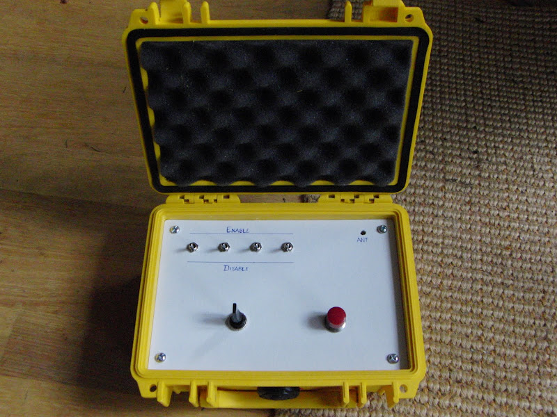
Functionally, I've abandoned the idea of multiple banks in a single-addressed pad control box. It works, but it makes things complicated. Instead, every bank will have an independent address. That means the big 16-pad box will actually have 4 addresses associated with it. Right now, the system can support 250 addresses for a total of 1000 ignition points.

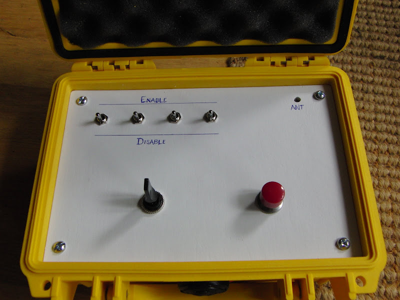
The console box has also evolved a bit. It's now a 1+ box solution. The base box can address up to 4 banks, and has 4 arm switches for the pads in each bank. The design also now sports an expansion plug. Expansion modules support 1-4 banks per module. Think of an operators phone at a receptionist's desk. There's the main phone, and a bunch of "add-on" modues that show all the lines in the system and can easily transfer calls from the main phone to any of the lines via push buttons.

I've also abandoned the idea that a small console could manage a 100 rocket drag race by addressing and arming individual pads. While I can have the microcontroller know which pads are armed, there's no way to easily convey that information to the operator. With this new "expansion module" design, only what's on the board is active. For example, assume the operator has bank 122 selected with pads A-C armed. If the operator were to change the bank selector to bank 128, all three pads on 122 would immediately disarm, and the corresponding pads on 128 would be armed/disarmed depending on the position of the switches.

A fully loaded console with 2 expansion modules can address up to 48 lines at once, and all the little lights will tell you pad status for each one. I think this makes a lot more sense from a usability perspective, and eliminates a huge potential mess regarding accidental launches because some pad was left armed, and there was no way to know it from glancing at the console.

Cheers,
- Ken
 
Here's a couple photos of the prototype 4-pad console. A few notes on this one:

1) This is a fixed address 4-pad. There's no address selector to manage multiple pad controllers.

2) The hole in the upper right is for the antenna. The panel mount bracket hasn't come in yet.

3) The lever on the lower left is getting replaced by a key switch. Didn't have a key switch handy, so I used the lever as a placeholder.

4) The launch button is a surplus button I happen to have around. The real button is on the way.

5) Battery for the unit is internal. Right now, you have to remove the front panel (4 screws in the corners) in order to access the battery. I'm not too happy with it. I'll probably add some external posts for an external battery unit, or to allow recharging of an internal battery, or something or that sort. For my own personal version, it will likely be an internal 3s LiPo with a charge plug exposed on the front panel.

6) Still needs indicator lights for status. Part of this first prototype build was to get through the initial layout and wiring to find all the pieces that I missed. Theory is great, but there's nothing like actual usage to figure out what still needs doing.

CIMG2261.JPG


CIMG2262.JPG
 
More for my own edifucation, but why use a mechanical relay for the firing circuits instead of an SCR? No mechanical contacts to weld, available in currents up to 100+ amps. All fire until the current stops flowing.

Chris.
 
More for my own edifucation, but why use a mechanical relay for the firing circuits instead of an SCR? No mechanical contacts to weld, available in currents up to 100+ amps. All fire until the current stops flowing.

Chris.

Mostly cost. Standard automotive relays can be had for as little $3-5 each. 30A SCRs/SSRs cost $25+
 
Back
Top