A5tr0 An0n
Well-Known Member
- Joined
- Sep 29, 2012
- Messages
- 521
- Reaction score
- 10
Introduction:
Seeing as I have been getting more and more into minimum diameter rockets, I felt it made more sense to start tower launching vs the traditional rail launching. So my thoughts on the tower were pretty simple and it took me about a day to design it; when designing it I had a couple of requirements in mind. I wanted it to be adjustable, mainly to fit 38mm and 54mm vehicles and I wanted it to be capable of breaking down and fitting in my SUV/trailer. I came up with a simple design and made a couple adjustments along the way. This tower has already been built and this thread is another one of my after the fact type build threads. With that being said I might have some documentation missing and therefore I am posting with what I got.
Below, this thread will be broken into 3 parts consisting of the design, assembly, and application. Now lets get to it.
Design:
A straight forward design that consist of 4 major components, all of which are listed below.
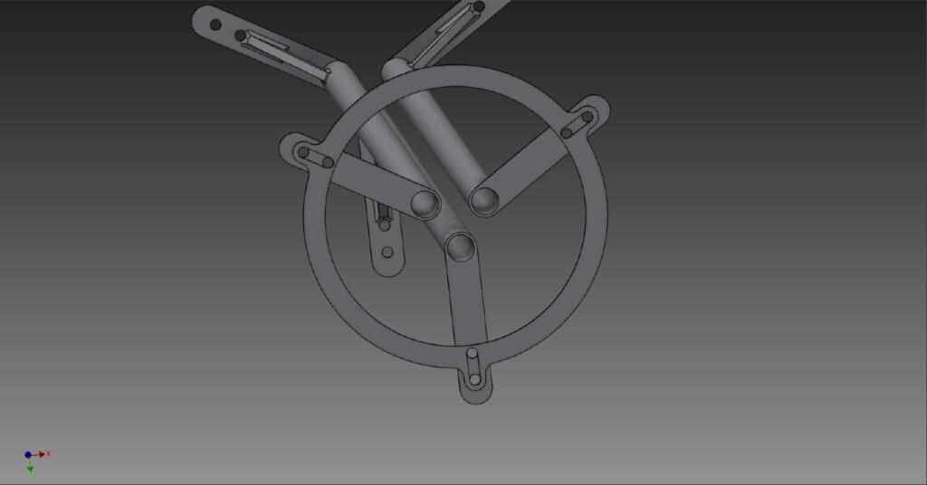
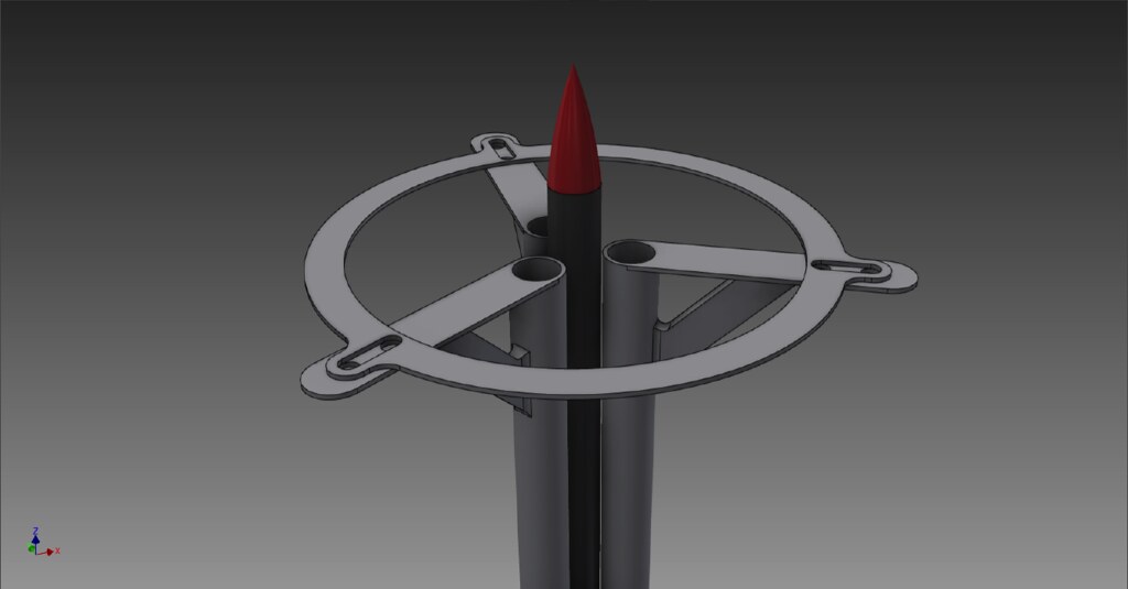
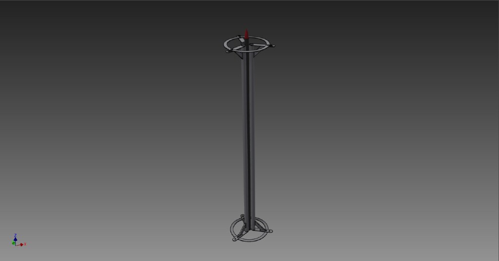
Main Structure:
This component should act as a means to structurally support the launch guides; there will be two of these, one placed aft and one fore of the guides. It is made of 0.125" thick Aluminum 6061-T6 and is cut into a circular shape that measures 12" ID, 14" OD, 2" width, and three 3" x 0.5" slots at 120 degree intervals.
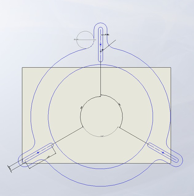
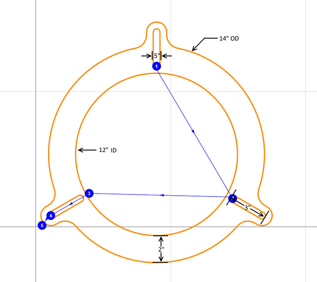
Some simple CAD pictures.
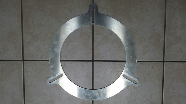
All finished.
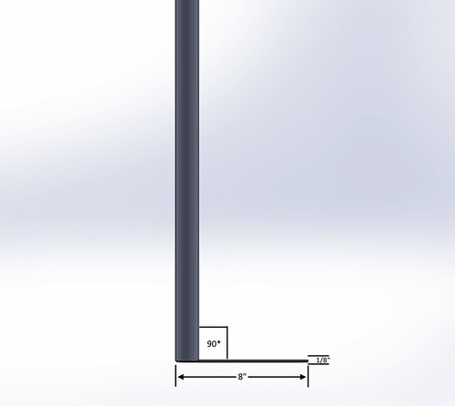
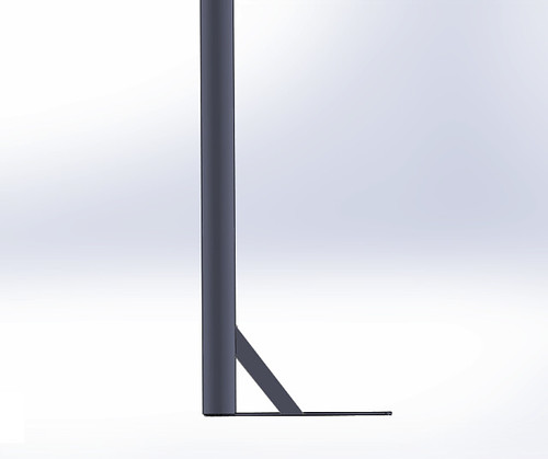
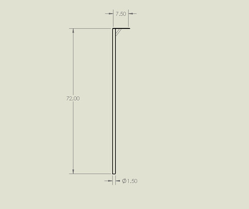
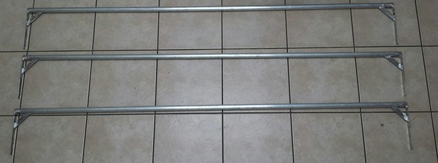
Launch Guides:
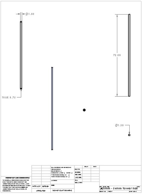
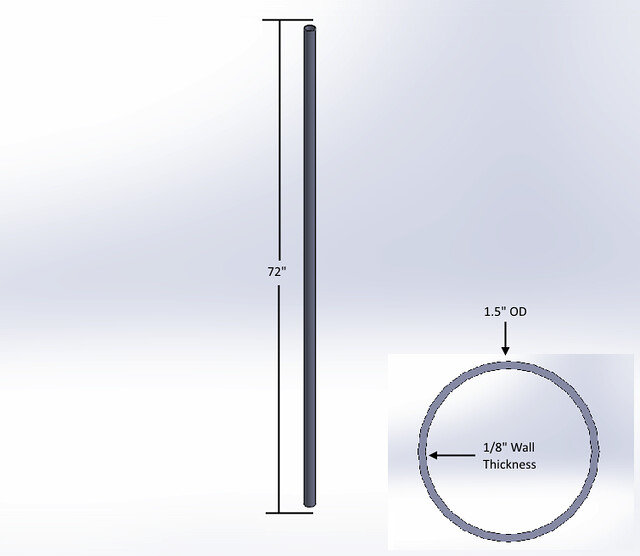
This components purpose is to provide a smooth and straight guide during the initial part of the boost. This allows a rail buttonless launch by guiding the rocket far enough/vertically straight until the fins become effective. The way this is achieved, is via a long tube (three of them to be exact) that are pressed against the vehicles sides. The guides are made from Aluminum 6063-T52 that measures 1.5" OD, 0.125" wall thickness, and 72" length. The reason I choose 6063 is because it has a surface finish that is far smoother than the other commercially available alloys. This made sense seeing as it will be pressed against the rocket.
These pictures speak for themselves.
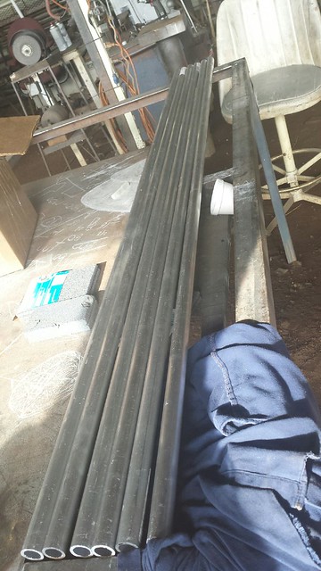
Launch guides acquired. Note that I only need 3 but I got six for another project.
Slot Profiles:
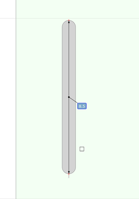
This components job is to connect the launch guides to the main structure. It is made of Aluminum 6061-T6 that measures 0.125" thick, 8.5" length, and 1" width; a total of 6 pieces are needed for this tower.
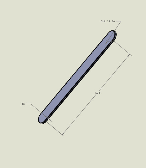
Speaks for itself.
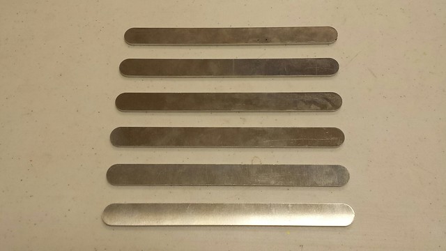
Done.
Gussets:
This components job is to structurally support the slot profiles. It is made from 0.125" thick Aluminum 6061-T6 and measures 4" length (from the longest point), 0.75" width, and is cut at 45 degree angles at each end. A total of six of these pieces are needed for the tower.
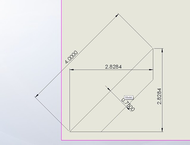
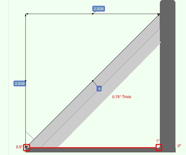
Pretty straight forward. In the second picture, forgot about the line done the middle of the gusset.
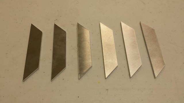
All done.
Assembly:
This section will describe the assembly of the tower. Some components will be permanently assembled where others are bolted together; I felt this allowed a mobile but sound construction technique. I will break this section into two parts, permeant and bolted assembly.
Permeant Assembly:
The launch guides, slot profiles, and gussets are all permanently joined together and thus become one piece. These components are permanently joined together via being welded into place. Below you can see how/where they are welded.
[Top and Bottom Left Photo: There is a error, the slot profile in both photos should measure 8.5". I am just to lazy to fix it.] First the slot profiles are welded to the launch guides and then the gusset is welded to the slot profile and launch guide. There are a total of two slot profiles per launch guide and also two gussets per launch rail. The slot profiles are welded onto the launch rails at 90 degrees inline with one another.
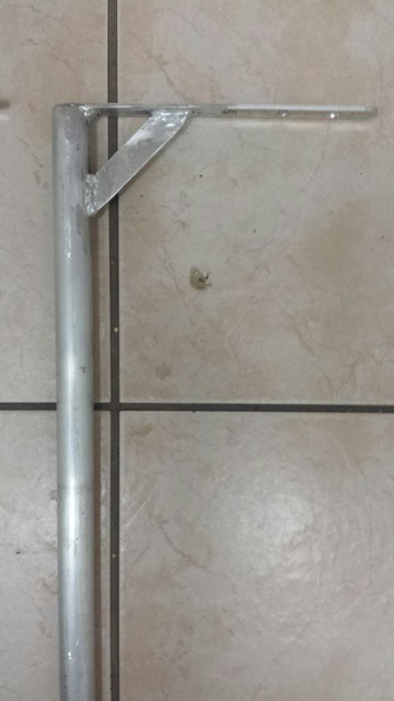
Here you can see the launch rail welded to the slot profile and then reinforced with the gusset. Now to repeat this 5 more times.
All done, pieces are now welded together.
Bolted Assembly:
With the launch guides, slot profiles, and gussets becoming one assembly, this leaves two components to be assembled on the field. These two components are the main structure and the guide assembly. These two parts are bolted together and thus are not permeant and allow for the mobile aspect of this tower. To bolt these two parts together I use a mixture of bolts, eyebolts, washers, rubber washers, and nuts. The eyebolts are to allow for this tower to be secured via ratchet tie downs and the rubber washers are used to mainly cause more friction, thus requiring more effort to be applied to move the guide assembly once it is tighten onto the main structure. All bolts are 5/16" x 1" and 3 out of the 6 eyebolts are 5/16", with the other 3 being 3/8", all washers are accordingly.
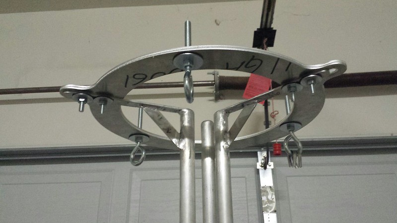
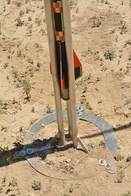
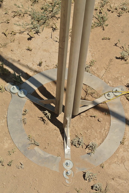
Here you can see it all bolted together. Note that this particular photograph has two main structures on top, this is for a modification that will be disclosed later. It is not for a single vehicle configuration.
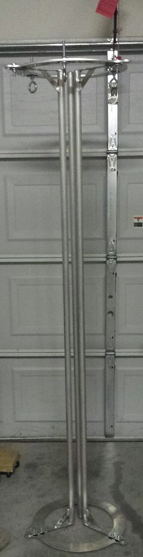
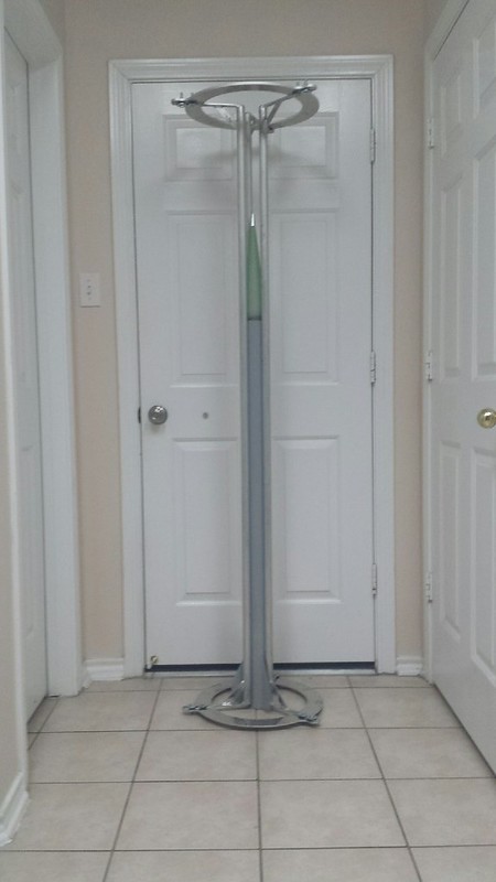
LEFT: Quickly assembled and not tightened down. Even so, seems to be pretty rugged. RIGHT: Assembled with a 54mm vehicle inside; simply center the vehicle and then adjust the rails and tighten. All else that needs to be done is the ratchet tie downs and the stakes. Note that prior to actual launch the vehicle is elevated off the ground and is not resting on the surface.
Application:
This section of the thread is dedicated to the use of the tower. You will see how it is ratcheted down with the vehicle inserted and ready for launch. I used three 1-1/4" X 16' ratchet tie downs to secure the tower. These tie downs have a working load of 700lbs. and a breaking strength of 2200lbs., so more than enough. The top main structure has three eyebolts that are equally spaced at 120 degree intervals; these serve as an anchor point for the tie downs. I also used three 18" metal stakes (pet stakes) that were screwed into the ground, yes these stakes have an inclined plane in the shape of a helix, wrapped around an axis or cylinder lol. So not so typical. They worked OK… I did manage to snap one but once they were in they worked fine.
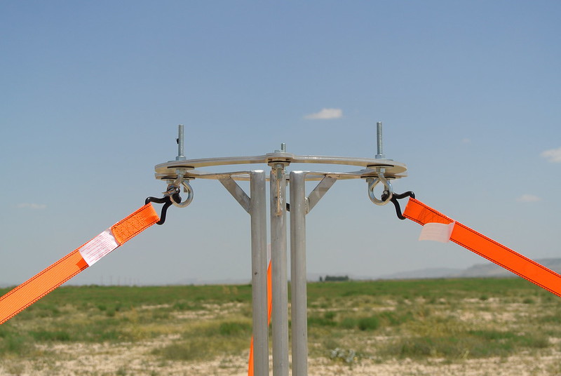
All ratcheted down and the tower is pretty firm. The tie downs connect via three different points equally placed at 120 degree intervals.
All assembled and ready to go.
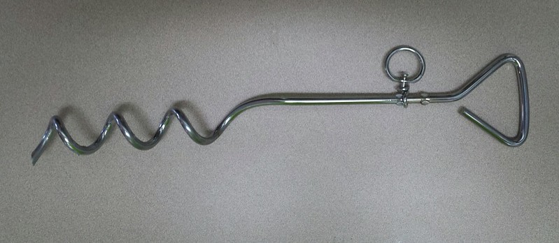
18" pet stakes that are used as the other anchor points for the ratcheted tie downs.
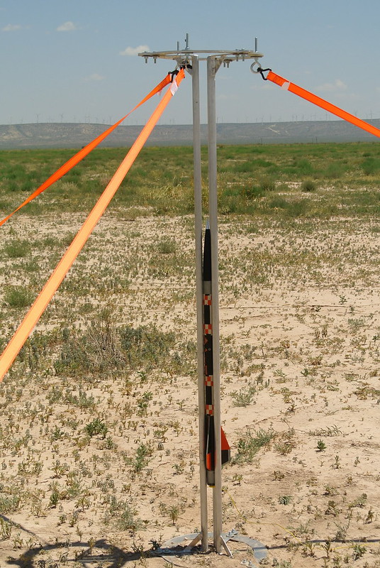
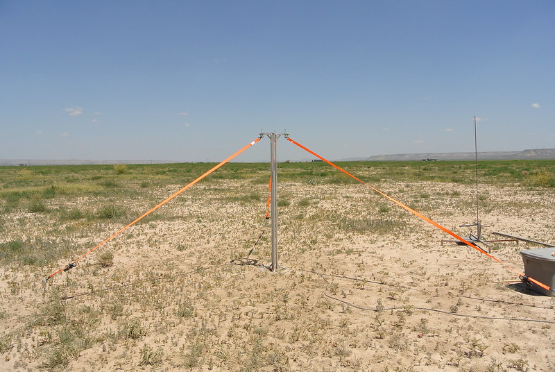
The vehicle is inserted and elevated off the ground about 1'. This gives 5' of tower that the vehicle is in.
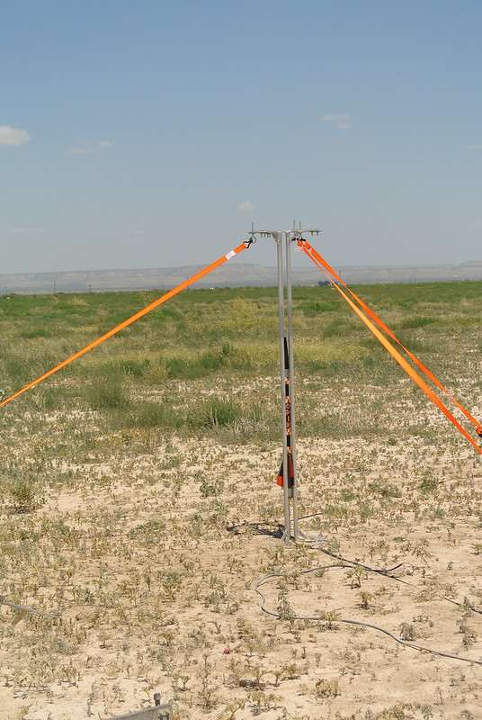
Another shot slightly farther away.
Conclusion:
Seeing as this was my first tower design and all in all, I am happy with the results. It works well, travels well, and is light and simple. With all of that being said there are some slight modifications that I plan on making in the future on my next tower (75mm - 98mm). I think this thread makes it kind of straight forward and hopefully easy to follow along. If not then please feel free to comment with anything that you may have.
Notes:
- Have some more CAD files that I need to find and upload.
- When using this tower for 38mm vehicles it is a little harder to setup and a little wobbly while setting up; I mostly designed it for 54mm vehicles but it works nonetheless.
- One modification that I am thinking about making is to add 3 legs to the bottom main structure. This would allow the tower to be elevated about 8"-12" off the ground without having to sacrifice launch guide length. The legs that I am envisioning would be the above mentioned length and about 1.5"-1.875" OD and cut to a slight angle allowing them to add more support to the tower vs having the three legs going straight down at 90 degrees.
Mat
Seeing as I have been getting more and more into minimum diameter rockets, I felt it made more sense to start tower launching vs the traditional rail launching. So my thoughts on the tower were pretty simple and it took me about a day to design it; when designing it I had a couple of requirements in mind. I wanted it to be adjustable, mainly to fit 38mm and 54mm vehicles and I wanted it to be capable of breaking down and fitting in my SUV/trailer. I came up with a simple design and made a couple adjustments along the way. This tower has already been built and this thread is another one of my after the fact type build threads. With that being said I might have some documentation missing and therefore I am posting with what I got.
Below, this thread will be broken into 3 parts consisting of the design, assembly, and application. Now lets get to it.
Design:
A straight forward design that consist of 4 major components, all of which are listed below.
Main Structure:
This component should act as a means to structurally support the launch guides; there will be two of these, one placed aft and one fore of the guides. It is made of 0.125" thick Aluminum 6061-T6 and is cut into a circular shape that measures 12" ID, 14" OD, 2" width, and three 3" x 0.5" slots at 120 degree intervals.
Some simple CAD pictures.
All finished.
Launch Guides:
This components purpose is to provide a smooth and straight guide during the initial part of the boost. This allows a rail buttonless launch by guiding the rocket far enough/vertically straight until the fins become effective. The way this is achieved, is via a long tube (three of them to be exact) that are pressed against the vehicles sides. The guides are made from Aluminum 6063-T52 that measures 1.5" OD, 0.125" wall thickness, and 72" length. The reason I choose 6063 is because it has a surface finish that is far smoother than the other commercially available alloys. This made sense seeing as it will be pressed against the rocket.
These pictures speak for themselves.
Launch guides acquired. Note that I only need 3 but I got six for another project.
Slot Profiles:
This components job is to connect the launch guides to the main structure. It is made of Aluminum 6061-T6 that measures 0.125" thick, 8.5" length, and 1" width; a total of 6 pieces are needed for this tower.
Speaks for itself.
Done.
Gussets:
This components job is to structurally support the slot profiles. It is made from 0.125" thick Aluminum 6061-T6 and measures 4" length (from the longest point), 0.75" width, and is cut at 45 degree angles at each end. A total of six of these pieces are needed for the tower.
Pretty straight forward. In the second picture, forgot about the line done the middle of the gusset.
All done.
Assembly:
This section will describe the assembly of the tower. Some components will be permanently assembled where others are bolted together; I felt this allowed a mobile but sound construction technique. I will break this section into two parts, permeant and bolted assembly.
Permeant Assembly:
The launch guides, slot profiles, and gussets are all permanently joined together and thus become one piece. These components are permanently joined together via being welded into place. Below you can see how/where they are welded.
[Top and Bottom Left Photo: There is a error, the slot profile in both photos should measure 8.5". I am just to lazy to fix it.] First the slot profiles are welded to the launch guides and then the gusset is welded to the slot profile and launch guide. There are a total of two slot profiles per launch guide and also two gussets per launch rail. The slot profiles are welded onto the launch rails at 90 degrees inline with one another.
Here you can see the launch rail welded to the slot profile and then reinforced with the gusset. Now to repeat this 5 more times.
All done, pieces are now welded together.
Bolted Assembly:
With the launch guides, slot profiles, and gussets becoming one assembly, this leaves two components to be assembled on the field. These two components are the main structure and the guide assembly. These two parts are bolted together and thus are not permeant and allow for the mobile aspect of this tower. To bolt these two parts together I use a mixture of bolts, eyebolts, washers, rubber washers, and nuts. The eyebolts are to allow for this tower to be secured via ratchet tie downs and the rubber washers are used to mainly cause more friction, thus requiring more effort to be applied to move the guide assembly once it is tighten onto the main structure. All bolts are 5/16" x 1" and 3 out of the 6 eyebolts are 5/16", with the other 3 being 3/8", all washers are accordingly.
Here you can see it all bolted together. Note that this particular photograph has two main structures on top, this is for a modification that will be disclosed later. It is not for a single vehicle configuration.
LEFT: Quickly assembled and not tightened down. Even so, seems to be pretty rugged. RIGHT: Assembled with a 54mm vehicle inside; simply center the vehicle and then adjust the rails and tighten. All else that needs to be done is the ratchet tie downs and the stakes. Note that prior to actual launch the vehicle is elevated off the ground and is not resting on the surface.
Application:
This section of the thread is dedicated to the use of the tower. You will see how it is ratcheted down with the vehicle inserted and ready for launch. I used three 1-1/4" X 16' ratchet tie downs to secure the tower. These tie downs have a working load of 700lbs. and a breaking strength of 2200lbs., so more than enough. The top main structure has three eyebolts that are equally spaced at 120 degree intervals; these serve as an anchor point for the tie downs. I also used three 18" metal stakes (pet stakes) that were screwed into the ground, yes these stakes have an inclined plane in the shape of a helix, wrapped around an axis or cylinder lol. So not so typical. They worked OK… I did manage to snap one but once they were in they worked fine.
All ratcheted down and the tower is pretty firm. The tie downs connect via three different points equally placed at 120 degree intervals.
All assembled and ready to go.
18" pet stakes that are used as the other anchor points for the ratcheted tie downs.
The vehicle is inserted and elevated off the ground about 1'. This gives 5' of tower that the vehicle is in.
Another shot slightly farther away.
Conclusion:
Seeing as this was my first tower design and all in all, I am happy with the results. It works well, travels well, and is light and simple. With all of that being said there are some slight modifications that I plan on making in the future on my next tower (75mm - 98mm). I think this thread makes it kind of straight forward and hopefully easy to follow along. If not then please feel free to comment with anything that you may have.
Notes:
- Have some more CAD files that I need to find and upload.
- When using this tower for 38mm vehicles it is a little harder to setup and a little wobbly while setting up; I mostly designed it for 54mm vehicles but it works nonetheless.
- One modification that I am thinking about making is to add 3 legs to the bottom main structure. This would allow the tower to be elevated about 8"-12" off the ground without having to sacrifice launch guide length. The legs that I am envisioning would be the above mentioned length and about 1.5"-1.875" OD and cut to a slight angle allowing them to add more support to the tower vs having the three legs going straight down at 90 degrees.
Mat
Last edited:
 NC… :|