The Build
There is a caveat in regards to this build thread. Since this is the first of its kind for me, I will be taking this build rather slow. This is good for me in a way, because I tend to get complacent and this kit will force me to slow down and be a little more thoughtful in my procedures. Please indulge me in my pace. Also, I know this kit is designated a mid-power, but since it will fly on Ds, I thought I would leave it in this group. If you feel it should be moved I understand.
The Kit
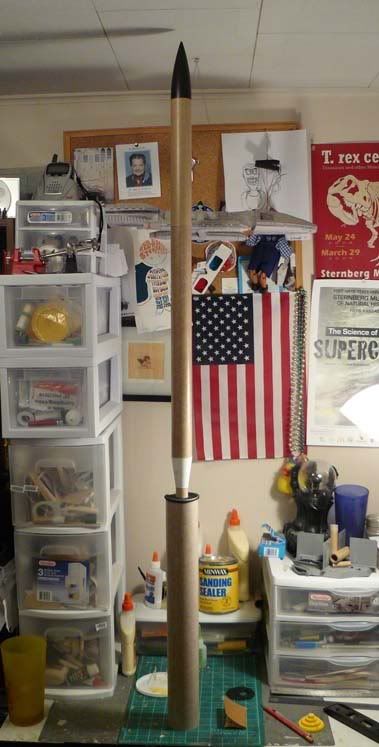
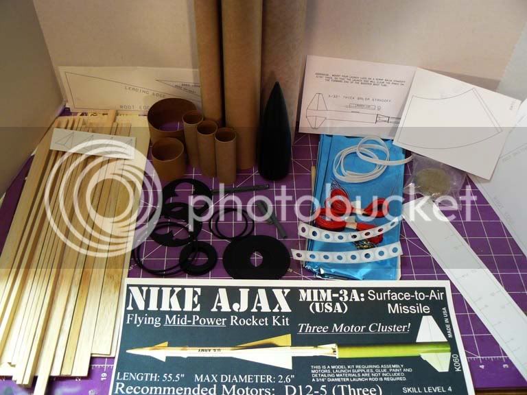
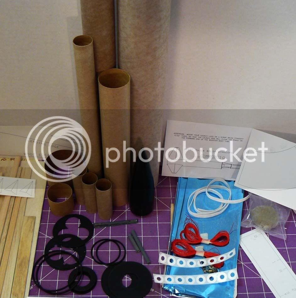
This is The Launch Pads Nike Ajax, mid-power, level four rocket, designed to fly on a cluster of three D12-5 motors. When completed, the rocket will measure 55.5 inches in length with a 2.6-inch diameter. Upon first inspection of the kit, you will notice it contains numerous parts and a veritable balsa lumberyard! You will notice that the fins are not precut and require the use of fin templates to trace-out the fins and cut them from the supplied balsa sheets. In addition to the fin templates, there is a paper transition for the booster and sustainer interstage and templates to create the antennas for the Nike missile. (The arrowhead shapes located to the left on the balsa pile) The kit also includes two 18 by 30 Mylar chutes that can be sized to two 24 inch octagonal chutes. The instructions are well written and I have only run across a procedural example or two that seemed vague. However, if you take your time, read the instructions carefully, dry-fit the sub assemblies and compare it to the diagrams I do not believe that you will have problems with the construction of this kit.
The kit layout:
Step 1.
As per of the instructions the first step is to break the clay into pellets and tamp them into the nose for weight. However, I chose to bypass this step for now. I ran across another build review on a TLP kit and one concern was that the clay was dry and per the instructions, the builder added water to return the clay to its original pliability. However, the reviewer stated that after doing this, it made the situation worse by turning the clay into a slimy unusable mess. In the end, they resorted to replacing the kits clay with modeling clay. In my example, the clay is dried- out as well and I suspect that I will weigh-out some modeling clay to replace the kits clay.
The Business End
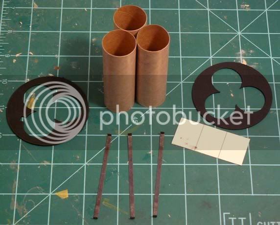
Since for now, I have bypassed step1 we will move into step 2, which concerns the construction of the cluster assembly. The build is straightforward and the assembly includes three motor tubes, three metal motor retainers, two centering rings, and card stock that is to be cut into three tabs to hold the metal retainers in place on the side of the motor tubes. TLP suggest the use of CA or concentrated white glue for the construction. I chose to use carpenters glue due to my lack of faith in a CA bond under extreme stresses. (maybe its just the CA that I use, I dunno)
Components of the cluster assembly:
Metal motor retainers in place
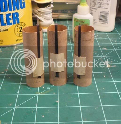
In addition, I have scrounged thrust rings from my spares box to add to this assembly because the retainer clips seem a bit light and I would feel better about that extra measure to prevent a motor from shooting out of the top of my rocket. After a few hours of gluing, fiddling, and drying, you have a completed, three -motor cluster assembly. An important note, the instructions are adamant that you DO NOT seal the gap between the three motor tubes. This gap serves as relief for overpressure of the tubes during the ejection charge and care must be taken when gluing this assembly together and avoid obstructing this gap. With my modification, the completed assembly weighs 0.5 oz or 16 grams. The only other modification I would have preferred to make is the shock cord. This kit uses the Estes (as I have heard it referred to and seems appropriate) tea bag shock cord mount. (Which I am not a big fan of.) I would rather had ran a length of Kevlar cord from the motor assembly to the shock cord up through the interstage tubing into the upper body tubing. Unfortunately I did not have that much Kevlar laying around and towards the top of the upper body tube there is a semi-bulkhead made of one of the smaller rings to serve as a divider for a chute compartment. I am unsure if this modification would have interfered with the ejection charge and deployment of the recovery device and with that, I will just stick with the instructions on this.
Dry fitting the assembly
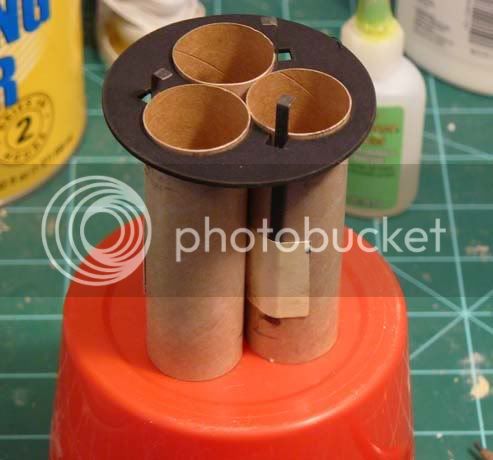
Assembly glued and drying:
Modification with the addition of thrust rings
Step 3, The Interstage Thrust Assembly
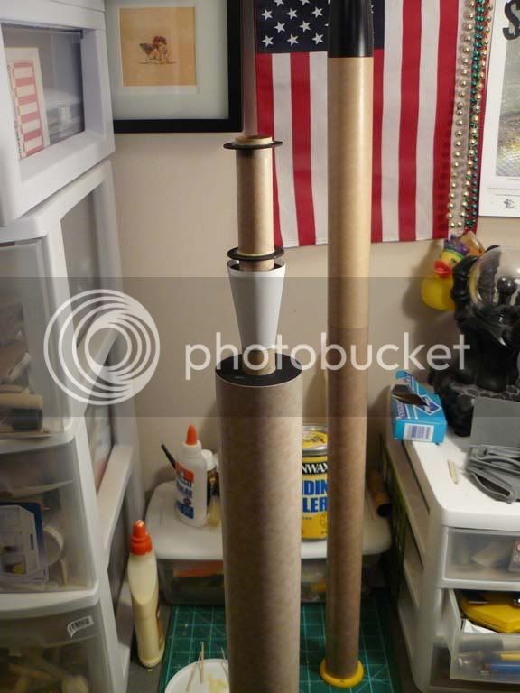
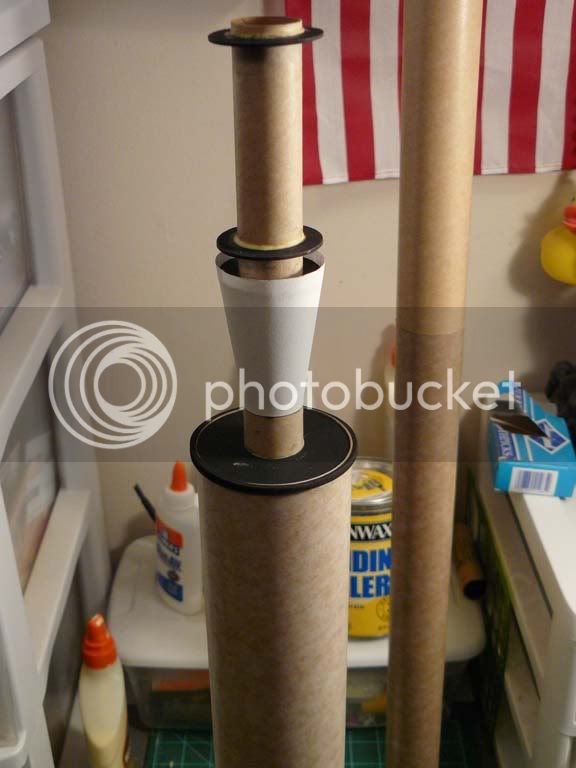
After completing the motor assembly, the next step is the construction of the interstage assembly which consists of a 12 inch- 1.0 diameter tube, a paper transition, 3/32 balsa and 1/16th balsa, two large centering rings and three small centering rings. Construction begins by cutting out the paper transition and gluing it in place at the 6-inch mark of the 12-inch tube. It is at this point, that I have not glued anything into place, but I have dry-fitted most of the assembly to give you an idea of how it will look. In review, the build, thus far, has not been difficult or complicated. If you take your time, dry-fit your parts, and compare it to the diagrams, you should be good to go.
Completed transition and dry-fitted interstage assembly
And this completes the first installment of this thread. I will try to have another ready by next week.
Thanks for your time.
Steve
There is a caveat in regards to this build thread. Since this is the first of its kind for me, I will be taking this build rather slow. This is good for me in a way, because I tend to get complacent and this kit will force me to slow down and be a little more thoughtful in my procedures. Please indulge me in my pace. Also, I know this kit is designated a mid-power, but since it will fly on Ds, I thought I would leave it in this group. If you feel it should be moved I understand.
The Kit
This is The Launch Pads Nike Ajax, mid-power, level four rocket, designed to fly on a cluster of three D12-5 motors. When completed, the rocket will measure 55.5 inches in length with a 2.6-inch diameter. Upon first inspection of the kit, you will notice it contains numerous parts and a veritable balsa lumberyard! You will notice that the fins are not precut and require the use of fin templates to trace-out the fins and cut them from the supplied balsa sheets. In addition to the fin templates, there is a paper transition for the booster and sustainer interstage and templates to create the antennas for the Nike missile. (The arrowhead shapes located to the left on the balsa pile) The kit also includes two 18 by 30 Mylar chutes that can be sized to two 24 inch octagonal chutes. The instructions are well written and I have only run across a procedural example or two that seemed vague. However, if you take your time, read the instructions carefully, dry-fit the sub assemblies and compare it to the diagrams I do not believe that you will have problems with the construction of this kit.
The kit layout:
Step 1.
As per of the instructions the first step is to break the clay into pellets and tamp them into the nose for weight. However, I chose to bypass this step for now. I ran across another build review on a TLP kit and one concern was that the clay was dry and per the instructions, the builder added water to return the clay to its original pliability. However, the reviewer stated that after doing this, it made the situation worse by turning the clay into a slimy unusable mess. In the end, they resorted to replacing the kits clay with modeling clay. In my example, the clay is dried- out as well and I suspect that I will weigh-out some modeling clay to replace the kits clay.
The Business End
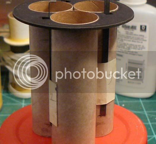
Since for now, I have bypassed step1 we will move into step 2, which concerns the construction of the cluster assembly. The build is straightforward and the assembly includes three motor tubes, three metal motor retainers, two centering rings, and card stock that is to be cut into three tabs to hold the metal retainers in place on the side of the motor tubes. TLP suggest the use of CA or concentrated white glue for the construction. I chose to use carpenters glue due to my lack of faith in a CA bond under extreme stresses. (maybe its just the CA that I use, I dunno)
Components of the cluster assembly:
Metal motor retainers in place
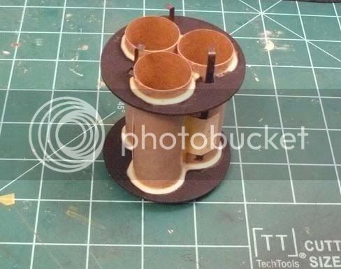
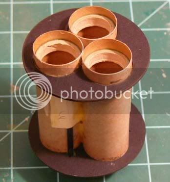
In addition, I have scrounged thrust rings from my spares box to add to this assembly because the retainer clips seem a bit light and I would feel better about that extra measure to prevent a motor from shooting out of the top of my rocket. After a few hours of gluing, fiddling, and drying, you have a completed, three -motor cluster assembly. An important note, the instructions are adamant that you DO NOT seal the gap between the three motor tubes. This gap serves as relief for overpressure of the tubes during the ejection charge and care must be taken when gluing this assembly together and avoid obstructing this gap. With my modification, the completed assembly weighs 0.5 oz or 16 grams. The only other modification I would have preferred to make is the shock cord. This kit uses the Estes (as I have heard it referred to and seems appropriate) tea bag shock cord mount. (Which I am not a big fan of.) I would rather had ran a length of Kevlar cord from the motor assembly to the shock cord up through the interstage tubing into the upper body tubing. Unfortunately I did not have that much Kevlar laying around and towards the top of the upper body tube there is a semi-bulkhead made of one of the smaller rings to serve as a divider for a chute compartment. I am unsure if this modification would have interfered with the ejection charge and deployment of the recovery device and with that, I will just stick with the instructions on this.
Dry fitting the assembly
Assembly glued and drying:
Modification with the addition of thrust rings
Step 3, The Interstage Thrust Assembly
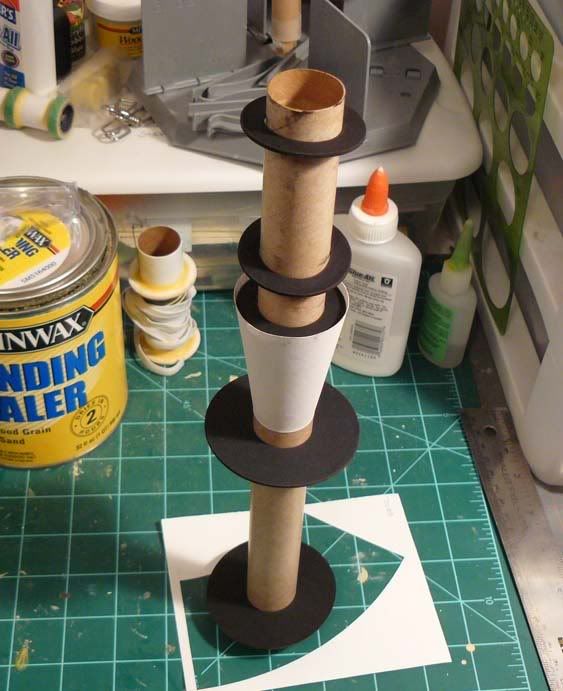
After completing the motor assembly, the next step is the construction of the interstage assembly which consists of a 12 inch- 1.0 diameter tube, a paper transition, 3/32 balsa and 1/16th balsa, two large centering rings and three small centering rings. Construction begins by cutting out the paper transition and gluing it in place at the 6-inch mark of the 12-inch tube. It is at this point, that I have not glued anything into place, but I have dry-fitted most of the assembly to give you an idea of how it will look. In review, the build, thus far, has not been difficult or complicated. If you take your time, dry-fit your parts, and compare it to the diagrams, you should be good to go.
Completed transition and dry-fitted interstage assembly
And this completes the first installment of this thread. I will try to have another ready by next week.
Thanks for your time.
Steve

 op:
op: