Charles_McG
Ciderwright
Rather than to stuff info into one of my other builds, or derail one of @Ez2cDave 's data threads, I'll start a new one for my current project.
Mind you - I'm not a crazy detail scale person. And I'm not a 'looks good at the M pad' modeler, either. I'm my own version of a happy medium.
At 1/5.2, a Malemute sounding rocket looks suspiciously like a Leviathan with smaller fins. My Nike Apache is a PSII Nike Smoke and a scratch built Apache. My Nike Tomahawk-12 uses the same booster with a modified Ventris. Building a scratch booster and modifying a Leviathan just seems to be the next step.
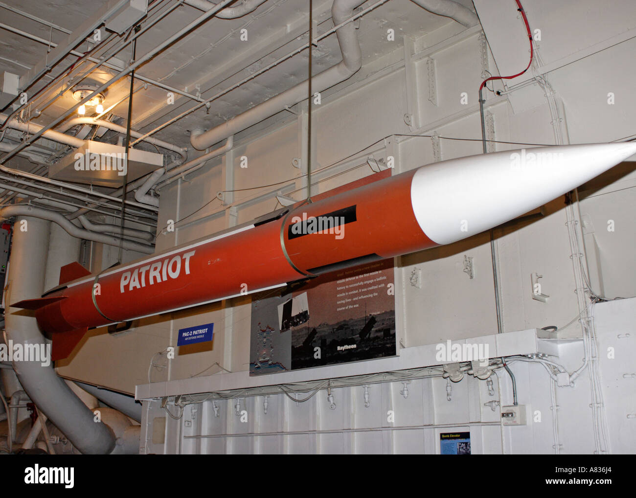
@PeterAlway covered the Terrier Malemute in the 2001 Supplement. Hi-Vis Dave has passed along other documents, including the academic paper covering the development of the Malemute motor. Those are great for the sustainer. I see references that the 'Improved Malemute' motor is supposed to be about 2" longer IRL. And that it's also supposed to be a Patriot missile motor. I've also seen references to NASA flights that seem to refer to the Improved Malemute with the same Thiokol motor designation as the original. Peter's write up says it's for the first flight. The biggest changes I see in later flight photos are the orange/white stripe Improved motor, a much longer payload, and often a conical nosecone instead of a 3:1 ogive.
Well, a longer payload suits - scale would be 7.75" and given the shoulders for an avbay and a big Daddy/Leviathan nosecone, there's not much room for a chute in there. And I might make more than one payload section and print me up another nosecone, just to get more rockets out of one build. I'm not going to try to model a specific flight.
Then my attention turned to the Terrier booster. At 1/5.2, my 3.44" made wrapped body tube is a nice match. And I can print up an interstage with one of @vcp 's SCAD generators and some tinkercad tinkering. But -which- fins. All the later pics show different fins than Peter, and a couple early pics, do.
I'm still collecting Terrier info, but I did find this high res photo from a Terrier Orion flight with is filling in gaps. I rotated upside down so I could read the printing on it.

Handily, there is a manufacturer's label on the fin. This is a 4.8 sq ft version - I think the original was 2.6.
I'm also working on the side label:

So far, I think I've got everything but one word.
NAVAL ORDNANCE STATION
INDIAN HEAD MARYLAND 11/82
BOOSTER GUIDED MISSILE MARK 12 MOD 1 S/N 9164/C-5738 R
??ORD DWG NO 173858 AA
PROPELLENT GRAIN GUIDED MISSILE MARK 73 MOD 0 LOT -35
IGNITER BOOSTER GUIDED MISSILE MARK 200 MOD 0
FIRING TEMPERATURE LIMITS 20 F TO 110F
STORAGE TEMPERATURE LIMITS 0 F TO 120 F
SEE PROPULSION UNIT DATA SHEET FOR EXPIRATION DATE OF PROPELLANTS
Mind you - I'm not a crazy detail scale person. And I'm not a 'looks good at the M pad' modeler, either. I'm my own version of a happy medium.
At 1/5.2, a Malemute sounding rocket looks suspiciously like a Leviathan with smaller fins. My Nike Apache is a PSII Nike Smoke and a scratch built Apache. My Nike Tomahawk-12 uses the same booster with a modified Ventris. Building a scratch booster and modifying a Leviathan just seems to be the next step.
@PeterAlway covered the Terrier Malemute in the 2001 Supplement. Hi-Vis Dave has passed along other documents, including the academic paper covering the development of the Malemute motor. Those are great for the sustainer. I see references that the 'Improved Malemute' motor is supposed to be about 2" longer IRL. And that it's also supposed to be a Patriot missile motor. I've also seen references to NASA flights that seem to refer to the Improved Malemute with the same Thiokol motor designation as the original. Peter's write up says it's for the first flight. The biggest changes I see in later flight photos are the orange/white stripe Improved motor, a much longer payload, and often a conical nosecone instead of a 3:1 ogive.
Well, a longer payload suits - scale would be 7.75" and given the shoulders for an avbay and a big Daddy/Leviathan nosecone, there's not much room for a chute in there. And I might make more than one payload section and print me up another nosecone, just to get more rockets out of one build. I'm not going to try to model a specific flight.
Then my attention turned to the Terrier booster. At 1/5.2, my 3.44" made wrapped body tube is a nice match. And I can print up an interstage with one of @vcp 's SCAD generators and some tinkercad tinkering. But -which- fins. All the later pics show different fins than Peter, and a couple early pics, do.
I'm still collecting Terrier info, but I did find this high res photo from a Terrier Orion flight with is filling in gaps. I rotated upside down so I could read the printing on it.
Handily, there is a manufacturer's label on the fin. This is a 4.8 sq ft version - I think the original was 2.6.
I'm also working on the side label:
So far, I think I've got everything but one word.
NAVAL ORDNANCE STATION
INDIAN HEAD MARYLAND 11/82
BOOSTER GUIDED MISSILE MARK 12 MOD 1 S/N 9164/C-5738 R
??ORD DWG NO 173858 AA
PROPELLENT GRAIN GUIDED MISSILE MARK 73 MOD 0 LOT -35
IGNITER BOOSTER GUIDED MISSILE MARK 200 MOD 0
FIRING TEMPERATURE LIMITS 20 F TO 110F
STORAGE TEMPERATURE LIMITS 0 F TO 120 F
SEE PROPULSION UNIT DATA SHEET FOR EXPIRATION DATE OF PROPELLANTS
")