


Stanchion, mount or post might work.Sticky-out things?
You are using an out of date browser. It may not display this or other websites correctly.
You should upgrade or use an alternative browser.
You should upgrade or use an alternative browser.
More Half-Baked Designs Thread
- Thread starter jqavins
- Start date
Help Support The Rocketry Forum:
This site may earn a commission from merchant affiliate
links, including eBay, Amazon, and others.
- Joined
- Aug 27, 2011
- Messages
- 11,638
- Reaction score
- 6,285
“Suspenders” doesn’t jive with my vision if what these do, but that’s just my take.We've called them fins, spokes, struts and now pylons. How about suspenders?
View attachment 480712
Experimental bamboo parts - called wing struts in the RC airplane realm - measure 1/16" x 3/16", and are of an aerofoil or streamline cross-section.
i intuitively can visualize them as
pylons
spoke fins
struts
all these imply the part Functions as an attachment of one piece to another.
of these, especially if structure is elongated in tail to nose direction so intended or not it ALSO DOES function as fin stabilizing the rocket, “Spoke Fin” or perhaps “Pylon Fin” or “Strut Fin” would convey the most descriptive definition, IMO.
”sticky-out things” is to broad and doesn’t have the specific connotation that these parts attach “something” to either a body tube, wing, or fin.
- Joined
- Aug 27, 2011
- Messages
- 11,638
- Reaction score
- 6,285
A purist looking to emphasize only the ring fin would attach it with stiff wires or small dowels.
I are a engineer, so using fins seems like the ”best way”,
I are a engineer, so using fins seems like the ”best way”,
- provides a lot of surface area, so attachment is easy AND strong.
- can but doesn’t have to be through the wall (wires or dowels likely would require this at the body attachment)
- contributes positively to the stability of the rocket (again, violates the ”purist” ethic, but seems like a nice bonus with little added drag or weight)
- if shaped and attached right (not all that difficult), automatically aligns the ring perfectly.
I strongly agree that any method chosen needs to deliver nearly perfect alignment of the ring with the body. I've found several ways to get it wrong, and the consequences are serious!A purist looking to emphasize only the ring fin would attach it with stiff wires or small dowels.
I are a engineer, so using fins seems like the ”best way”,
- provides a lot of surface area, so attachment is easy AND strong.
- can but doesn’t have to be through the wall (wires or dowels likely would require this at the body attachment)
- contributes positively to the stability of the rocket (again, violates the ”purist” ethic, but seems like a nice bonus with little added drag or weight)
- if shaped and attached right (not all that difficult), automatically aligns the ring perfectly.
Note:
A nice photo of a ring tail is featured on page 12 of Sport Rocketry magazine, September/October edition. The rocketeer is Mark Rapf and his rocket is called Kickstarter.
Alright, alright, "sticky-outy support thingies" then.”sticky-out things” is to broad and doesn’t have the specific connotation that these parts attach “something” to either a body tube, wing, or fin.
")
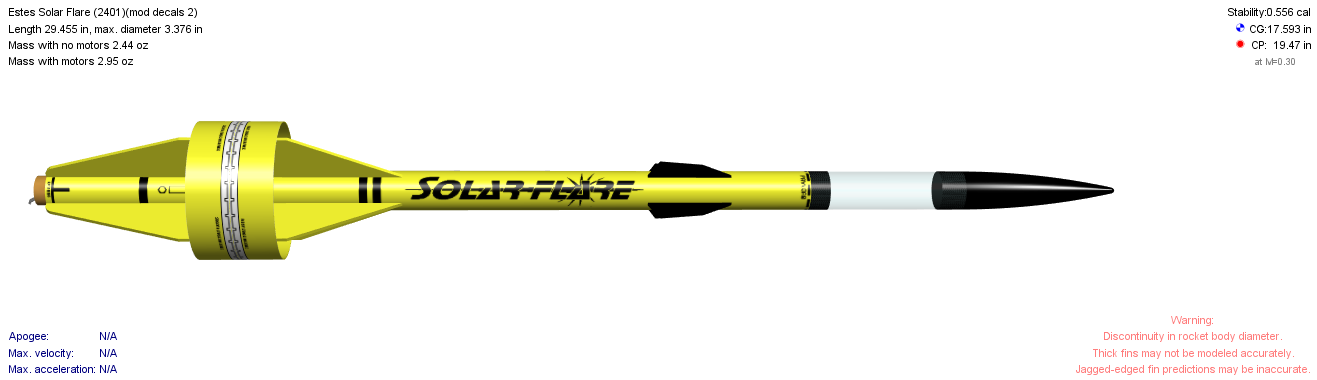
But seriously, while many angels can, indeed, dance on the head of a pin, this angel is sticking with "pylon". With any contribution to stability considered incidental, there's no need for different terms in different designs, except in extreme cases like the Estes Solar Flare; in that case, the items in question are so large that the rings are largely cosmetic, and it's their effect on stability that's incidental, so I'd call the sticky-outy support thingies fins. But that's the oddball. (I went looking for a picture, and this from our very own @K'Tesh is the best one out there.)
Attachments

I would suggest that the rings on the Solar Flare are indeed contributing a large amount to stability, regardless of the size of the other fins.But seriously, while many angels can, indeed, dance on the head of a pin, this angel is sticking with "pylon". With any contribution to stability considered incidental, there's no need for different terms in different designs, except in extreme cases like the Estes Solar Flare; in that case, the items in question are so large that the rings are largely cosmetic, and it's their effect on stability that's incidental, so I'd call the sticky-outy support thingies fins. But that's the oddball.
But anyway, the reason I don't use "pylons" is that it sort of implies fins whose primary (or perhaps sole) purpose is just to hold the ring. That does not apply to either of my ring designs, where the fins are proper fins that also just happen to serve as a point of attachment for a ring.
Now @Dotini 's latest with what appear to be chopsticks as supports of the ring... well, those would seem to have earned the use of "pylons".
This is the final hair that I will split on this topic.
I don't doubt that that rings on the Solar Flare move the CP substantially. I seriously doubt, however, that such movement is important, as the CP would be in a completely acceptable place without them. And the rings appear, to me, to be intended merely as style elements. So I would call their effect both substantial and incidental, and thus call the connecting members fins.
I have now proven, to my own satisfaction at least, that the matter is completely subjective.
"Incidental" is not the same as "small". I would call the effect that something has incidental if it is not the purpose for which the thing is there and it is not necessary regarding the overall function of whatever it is the effect affects. In the case of most ring tail designs, that is, the effect of the connecting members between the body tube and ring may be substantial, but it it's not the reason those members are present (the reason being to connect the ring) and it is not needed to make the rocket stabile, as the ring would do that even if held only by taught fishing line. So the members' effect may be substantial, but is never the less incidental. Thus, in my opinion, they are pylons, not fins. (Note, I did say in most ring tail designs. Your designs are often anything but typical.)I would suggest that the rings on the Solar Flare are indeed contributing a large amount to stability, regardless of the size of the other fins.
I don't doubt that that rings on the Solar Flare move the CP substantially. I seriously doubt, however, that such movement is important, as the CP would be in a completely acceptable place without them. And the rings appear, to me, to be intended merely as style elements. So I would call their effect both substantial and incidental, and thus call the connecting members fins.
I have now proven, to my own satisfaction at least, that the matter is completely subjective.
- Joined
- Aug 27, 2011
- Messages
- 11,638
- Reaction score
- 6,285
A rose by any other name…..
Joe -- sorry, realized after seeing Neil's half-baked design thread and re-reading the intro to this thread that this was YOUR half-baked design thread. I thought it was a general half-baked design thread. Should I make my own half-baked design thread or is there a general one???
No, no. It is a general half-baked design thread.
OK, Neil, two can play at this game. Or more than two... After this, everyone (except Neil
Thanks for all the kind words and ideas on my half (or less) baked ideas. Now come on, folks, let's have someone else's!
No, no. It is a general half-baked design thread.
Ah great!!!
Well another half baked design I am trying is version 2 of a mini-engine powered F-117 Nighthawk. This is fully baked in real life and as a MUCH larger rocket glider but I decided I would try a 3D printed version for mini-engines. This small version is appealing since the whole design only takes like 5 hours to print (I know that seems like a long time to those of you who do not get stuck doing 20+ hour prints). My original design tried to use a sled to pop out the engine and weight so the model might conceivably glide down... Instead the engine got stuck and the ejection charge ripped the front end of the design off and cracked the 3D print in a number of places.
I also needed more weight to [possibly] make this stable. So I decided why fight it and try a traditional nose cone ejection with 1/2oz of weight in nose (about 2x what I had originally and puts CG at about halfway point in model). This is very close to the weight limit for a mini engine so if this does not work I will likely scrap this until I can try a full-sized boosted glider version.


Here's one that's "half-baked", but more in the sense of "I didn't put a lot of thought into this and realized that it was probably a bad/impossible idea." It's a stock Estes Star Orbiter loaded with the most powerful motor (by total impulse) that will fit in the stock 29mm mount: the Ratt I90L hybrid motor.

The first problem is pretty obvious: There's not enough room for that huge oxidizer tank. I ended up deciding it wasn't really a big deal, the main obstruction being the bottom of the nose. Removing the bottom edge creates enough room for it, and there might be room around the oxidizer tank for the shock cord and parachute (just work with me here, alright?)
Second problem: Obviously that long motor would put a lot of stress on the motor mount from not having a centering ring towards the front end. I just decided to ignore this for now. If I were to actually build this, I could slide a removable one in and have it rest on top of the tube coupler.
Third problem: The 2D flight profile indicated that the rocket would likely shake itself apart. I was initially puzzled by this, until I consulted Stine's book and realized that this configuration perfectly matched his description of a statically stable but dynamically unstable model. The fins are too small to produce sufficient restoring force for that heavy motor.
I set to work increasing the fin area. I didn't bother with making the through-the-wall tabs physically compatible with stock body tube and motor mount, I just wanted to see what external modifications it would take to bring about dynamic stability. After some assistance from @kuririn I was able to rapidly throw together some simulations with fins of increasing upscale factors over the original. I ended up discovering that the minimum upscale required to dynamically stabilize the rocket was a factor of 16 by area, 4 by linear dimensions. This was the result.

That, of course, is just silly. It's probably also completely infeasible with 1/8th inch balsa, and it would be statically unstable on other I-type motors that don't have that oxidizer tank to push the CG forward. The Cesaroni I243, for example, would have the CG over an inch aft of CP.
So I drew the conclusion that I had at the start: this one will definitely remain a paper project. Fun to think about but entirely impractical to actually build and fly. I can probably think of about a dozen other things wrong with a design like this, and I'm sure others can think of a dozen more, but this was enough to convince me to abandon it.
The first problem is pretty obvious: There's not enough room for that huge oxidizer tank. I ended up deciding it wasn't really a big deal, the main obstruction being the bottom of the nose. Removing the bottom edge creates enough room for it, and there might be room around the oxidizer tank for the shock cord and parachute (just work with me here, alright?)
Second problem: Obviously that long motor would put a lot of stress on the motor mount from not having a centering ring towards the front end. I just decided to ignore this for now. If I were to actually build this, I could slide a removable one in and have it rest on top of the tube coupler.
Third problem: The 2D flight profile indicated that the rocket would likely shake itself apart. I was initially puzzled by this, until I consulted Stine's book and realized that this configuration perfectly matched his description of a statically stable but dynamically unstable model. The fins are too small to produce sufficient restoring force for that heavy motor.
I set to work increasing the fin area. I didn't bother with making the through-the-wall tabs physically compatible with stock body tube and motor mount, I just wanted to see what external modifications it would take to bring about dynamic stability. After some assistance from @kuririn I was able to rapidly throw together some simulations with fins of increasing upscale factors over the original. I ended up discovering that the minimum upscale required to dynamically stabilize the rocket was a factor of 16 by area, 4 by linear dimensions. This was the result.
That, of course, is just silly. It's probably also completely infeasible with 1/8th inch balsa, and it would be statically unstable on other I-type motors that don't have that oxidizer tank to push the CG forward. The Cesaroni I243, for example, would have the CG over an inch aft of CP.
So I drew the conclusion that I had at the start: this one will definitely remain a paper project. Fun to think about but entirely impractical to actually build and fly. I can probably think of about a dozen other things wrong with a design like this, and I'm sure others can think of a dozen more, but this was enough to convince me to abandon it.
Yeah, we rarely need to think about dynamic flight characteristics like restoring torque over moment of inertia and damping ratio.
And this brings up an old question in my head: if I understand this right, the CG of a hybrid moves aft during its burn, since the oxidizer tank is forward of the fuel grain and the oxidizer weighs more than the fuel.
(It might even change direction at some point during the flight. Consider letting the liquid out of a bottle, where the liquid initially weights more than the bottle does. (The figure is based on initial liquid weight being four time the bottle weight.)


And this brings up an old question in my head: if I understand this right, the CG of a hybrid moves aft during its burn, since the oxidizer tank is forward of the fuel grain and the oxidizer weighs more than the fuel.
- With end burners, the motor CG moves forward during the burn, while the motor weight is decreasing, and both of those move the rocket CG forward.
- With core burners, the motor CG doesn't move appreciably, and the decreasing weight of the motor still causes the rocket CG to move forward.
- But with a hybrid, which has the motor CG moving aft while the motor total weight is decreasing, these two things work against each other.
(It might even change direction at some point during the flight. Consider letting the liquid out of a bottle, where the liquid initially weights more than the bottle does. (The figure is based on initial liquid weight being four time the bottle weight.)
That sounds about right to me. I can’t really think of anything wrong with it.Yeah, we rarely need to think about dynamic flight characteristics like restoring torque over moment of inertia and damping ratio.
And this brings up an old question in my head: if I understand this right, the CG of a hybrid moves aft during its burn, since the oxidizer tank is forward of the fuel grain and the oxidizer weighs more than the fuel.
So which way does one expect the rocket CG to move? Obviously that depends on the fraction of the total rocket weight that's in the motor, and in a case like this one it will surely be going the wrong way. But in a more typical case, what does one expect?
- With end burners, the motor CG moves forward during the burn, while the motor weight is decreasing, and both of those move the rocket CG forward.
- With core burners, the motor CG doesn't move appreciably, and the decreasing weight of the motor still causes the rocket CG to move forward.
- But with a hybrid, which has the motor CG moving aft while the motor total weight is decreasing, these two things work against each other.
(It might even change direction at some point during the flight. Consider letting the liquid out of a bottle, where the liquid initially weights more than the bottle does. (The figure is based on initial liquid weight being four time the bottle weight.)
View attachment 481984
View attachment 481985
For the dynamic stability question, I’ve started thinking about it in terms of the INTENSITY of the pressure that’s centered on the CP point. With small fins and not a lot of restoring force it
might be like this:

While for a rocket with better dynamic stability it might be like this:

A much stronger restoring force that can prevent it from tumbling under thrust.
I’m on the go at the moment but when I get home I’ll check the stability of the airframe, both empty and with a burned out casing.
boatgeek
Well-Known Member
- Joined
- Dec 27, 2014
- Messages
- 7,414
- Reaction score
- 7,964
@Nytrunner did a Star Orbiter on a large motor recently. I don't remember if it used the 29mm motor mount or was assumed to be a 38mm mount. IIRC, it rekitted itself shortly into flight.Here's one that's "half-baked", but more in the sense of "I didn't put a lot of thought into this and realized that it was probably a bad/impossible idea." It's a stock Estes Star Orbiter loaded with the most powerful motor (by total impulse) that will fit in the stock 29mm mount: the Ratt I90L hybrid motor.
The first problem is pretty obvious: There's not enough room for that huge oxidizer tank. I ended up deciding it wasn't really a big deal, the main obstruction being the bottom of the nose. Removing the bottom edge creates enough room for it, and there might be room around the oxidizer tank for the shock cord and parachute (just work with me here, alright?)
Second problem: Obviously that long motor would put a lot of stress on the motor mount from not having a centering ring towards the front end. I just decided to ignore this for now. If I were to actually build this, I could slide a removable one in and have it rest on top of the tube coupler.
Third problem: The 2D flight profile indicated that the rocket would likely shake itself apart. I was initially puzzled by this, until I consulted Stine's book and realized that this configuration perfectly matched his description of a statically stable but dynamically unstable model. The fins are too small to produce sufficient restoring force for that heavy motor.
I set to work increasing the fin area. I didn't bother with making the through-the-wall tabs physically compatible with stock body tube and motor mount, I just wanted to see what external modifications it would take to bring about dynamic stability. After some assistance from @kuririn I was able to rapidly throw together some simulations with fins of increasing upscale factors over the original. I ended up discovering that the minimum upscale required to dynamically stabilize the rocket was a factor of 16 by area, 4 by linear dimensions. This was the result.
That, of course, is just silly. It's probably also completely infeasible with 1/8th inch balsa, and it would be statically unstable on other I-type motors that don't have that oxidizer tank to push the CG forward. The Cesaroni I243, for example, would have the CG over an inch aft of CP.
So I drew the conclusion that I had at the start: this one will definitely remain a paper project. Fun to think about but entirely impractical to actually build and fly. I can probably think of about a dozen other things wrong with a design like this, and I'm sure others can think of a dozen more, but this was enough to convince me to abandon it.
Personally, if I was headed this direction, I'd choose either a reinforced 29mm model (an excuse to get a 6XL case!) or go whole hog and do it minimum diameter. The 38mm MD options would get you above the altitude from the Rattworks motor, and you have more DMS options in case you don't want to risk a casing in that kind of rocket.
The stock mount is 29mm but the body tube is 42, so a 38mm mount could hypothetically work. But I’m not surprised about that result, some simulations had the thing tumbling rapidly at ~400 ft, too violently to possibly stay together.@Nytrunner did a Star Orbiter on a large motor recently. I don't remember if it used the 29mm motor mount or was assumed to be a 38mm mount. IIRC, it rekitted itself shortly into flight.
Personally, if I was headed this direction, I'd choose either a reinforced 29mm model (an excuse to get a 6XL case!) or go whole hog and do it minimum diameter. The 38mm MD options would get you above the altitude from the Rattworks motor, and you have more DMS options in case you don't want to risk a casing in that kind of rocket.
I’m currently working on one, almost all stock except using 24-hour epoxy for everything and papering the fins. I’m almost certain that I’m going to shred it at some point but I’m hoping I can get it to the top of the F range before it disintegrates.
boatgeek
Well-Known Member
- Joined
- Dec 27, 2014
- Messages
- 7,414
- Reaction score
- 7,964
I forgot that it was 42mm instead of 38mm. That has the added "benefit" of removing all motor length limitations since the 38mm motor could slide inside the coupler. J anyone?The stock mount is 29mm but the body tube is 42, so a 38mm mount could hypothetically work. But I’m not surprised about that result, some simulations had the thing tumbling rapidly at ~400 ft, too violently to possibly stay together.
I’m currently working on one, almost all stock except using 24-hour epoxy for everything and papering the fins. I’m almost certain that I’m going to shred it at some point but I’m hoping I can get it to the top of the F range before it disintegrates.

I'm guessing that your limiting factor will be the body tube crumpling rather than the fins coming apart, though I could certainly be wrong. If you go as gentle as you can on average thrust, you should be able to get up into the G range. A G33 Mellow from CTI would take it well out of sight.
J anyone?
Loki apparently manufactures two different K motors in that diameter, if you want it to actually orbit a star. Or crush the body tube under 140 pounds of thrust.
But if you really do go with those huge fins in 1/8" balsa, they'd flutter in in the merest zephyr. Since you plan to paper them, they might survive a modest breeze.
Oh hell no I’m not building those fins. I’m just going stock, it’s not worth the trouble.But if you really do go with those huge fins in 1/8" balsa, they'd flutter in in the merest zephyr. Since you plan to paper them, they might survive a modest breeze.
I've generally not had much interest in rocket gliders, but this is a cool looking concept that I think could be trimmed to work. I need someone with experience to weigh in.
All shapes and relative sizes are are preliminary. The wing planform, especially, is not really what I want, but just something of the right type that I could draw quickly.
Here are the top and side views in launch configuration:

The ejection charge kicks the spent motor back but not out, shifting the CG aft. I know that's a tried and true method.

Two things: Yes, I know, the forward tips are very breaky. And yes, I know, they'd not be so breaky if the body tube went all the way up. But I don't want that. I like the gap between the forward parts. That's part of what makes it different and cool.
The big question is can I make the engine kicking back cause a sufficient CG shift without also making the breaky tips so light that they are super-duper breaky. Or am I all wet in the first place thinking that this could ever be trimmed to glide at all?
It's all because Cylon Raider designs from posts 225 to 233 have been kicking around in my head until it hit me: that thing might glide!"
All shapes and relative sizes are are preliminary. The wing planform, especially, is not really what I want, but just something of the right type that I could draw quickly.
Here are the top and side views in launch configuration:
The ejection charge kicks the spent motor back but not out, shifting the CG aft. I know that's a tried and true method.
Two things: Yes, I know, the forward tips are very breaky. And yes, I know, they'd not be so breaky if the body tube went all the way up. But I don't want that. I like the gap between the forward parts. That's part of what makes it different and cool.
The big question is can I make the engine kicking back cause a sufficient CG shift without also making the breaky tips so light that they are super-duper breaky. Or am I all wet in the first place thinking that this could ever be trimmed to glide at all?
It's all because Cylon Raider designs from posts 225 to 233 have been kicking around in my head until it hit me: that thing might glide!"
Last edited:
mjennings
Well-Known Member
- Joined
- Jan 17, 2009
- Messages
- 2,114
- Reaction score
- 389
Hmmm if you made the fwd spikes T sections they might be less breaky. There's a lot of aft weight there, just a gut feel but just the weight of the spent casings might not be enough. Might have to get real crazy with some elastic and weights that move from far forward for boost and go way back for glide.
Another option for the breakiness would be to make them out of plywood. Of course, that increases the mass and makes moving the CG harder, so maybe do it in two pieces, with balsa most of the way up and plywood where it counts. I'd have to be using multiple pieces of balsa anyway, for grain direction.
And I could make the big lobes at the rear smaller to save weight. As I said, all the particular shapes and sizes are subject to change..
I was also thinking, over the weekend, that while the ellipses intersecting the lobes give yaw stability, nothing here would give roll stability. Maybe I should slant the ellipses symmetrically to get some dihedral. But then, what looks like dihedral on "top" is anhedral on the bottom, so maybe it wouldn't work. At this point, I have just passed from "only know a little" to "totally out of my depth". I might have to split the elliptical pieces to get dihedral on both sides.
I observed an excellent example last week of a rocket with only two fins demonstrating excellent stability in both yaw and roll. The rocketeer, a young lad of perhaps 12, forced his rocket to spin on ascent by glueing fairly small "ailerons" onto the traillng edges of his two fins.Another option for the breakiness would be to make them out of plywood. Of course, that increases the mass and makes moving the CG harder, so maybe do it in two pieces, with balsa most of the way up and plywood where it counts. I'd have to be using multiple pieces of balsa anyway, for grain direction.
And I could make the big lobes at the rear smaller to save weight. As I said, all the particular shapes and sizes are subject to change..
I was also thinking, over the weekend, that while the ellipses intersecting the lobes give yaw stability, nothing here would give roll stability. Maybe I should slant the ellipses symmetrically to get some dihedral. But then, what looks like dihedral on "top" is anhedral on the bottom, so maybe it wouldn't work. At this point, I have just passed from "only know a little" to "totally out of my depth". I might have to split the elliptical pieces to get dihedral on both sides.
But that's the opposite of roll stability. Rocket spin and glider roll are the same thing. (For a typical rocket, i.e. one with circular symmetry, pitch and yaw are equivalent.)
Thanks everyone -- somehow I missed the follow-up conversation about the Raider rocket... I really appreciate the thinking / effort to help make that thing stable.
I have been using 2mm basswood for all my fins these days (mainly because I wound up with 40x 200mmx300mm sheets of it (Amazon sent me my order 2x when they could not track the first shipment - which finally also arrived like a month later). These are less than $1 per sheet (well less than $.50 per sheet when you get a double order) and I have also found that the 2mm basswood is amazingly durable for larger fins, wings, etc... (at least for LPR)). The sheets can warp a little and I have had that issue to some extent with larger fins. However, I am amazed at how well the massive fins on my R1 Rocket worked or how the wings on the Boeing Bomarc worked out. They also work well on the Raider.
I think I just need to commit to making a slightly larger version of this rocket with a pair of mini-engines in the rear that are canted to make it spin/roll. One of my bigger issues was jamming a recover device in there and my little mylar streamer did not deploy well in my earlier tests. Larger rocket would help. Having the weights or engines eject w/ their own recovery device would be a good approach.
I also have some interest (but not enough knowledge) to make a glider rocket. The only forward-flying prototype I have ever flown actually seem to glide pretty well late in the launch / after engines were spent -- just unstable on launch / did not ascend enough (hence the goal of spinning it). It may have been more stable after the initial engine burn so more weight further forward might help (the smoke plume fake fins I thought about adding aft of engines might help also).
Another option for the breakiness would be to make them out of plywood. Of course, that increases the mass and makes moving the CG harder, so maybe do it in two pieces, with balsa most of the way up and plywood where it counts. I'd have to be using multiple pieces of balsa anyway, for grain direction.
I have been using 2mm basswood for all my fins these days (mainly because I wound up with 40x 200mmx300mm sheets of it (Amazon sent me my order 2x when they could not track the first shipment - which finally also arrived like a month later). These are less than $1 per sheet (well less than $.50 per sheet when you get a double order) and I have also found that the 2mm basswood is amazingly durable for larger fins, wings, etc... (at least for LPR)). The sheets can warp a little and I have had that issue to some extent with larger fins. However, I am amazed at how well the massive fins on my R1 Rocket worked or how the wings on the Boeing Bomarc worked out. They also work well on the Raider.
I observed an excellent example last week of a rocket with only two fins demonstrating excellent stability in both yaw and roll. The rocketeer, a young lad of perhaps 12, forced his rocket to spin on ascent by glueing fairly small "ailerons" onto the traillng edges of his two fins.
I think I just need to commit to making a slightly larger version of this rocket with a pair of mini-engines in the rear that are canted to make it spin/roll. One of my bigger issues was jamming a recover device in there and my little mylar streamer did not deploy well in my earlier tests. Larger rocket would help. Having the weights or engines eject w/ their own recovery device would be a good approach.
I've generally not had much interest in rocket gliders, but this is a cool looking concept that I think could be trimmed to work. I need someone with experience to weigh in.
I also have some interest (but not enough knowledge) to make a glider rocket. The only forward-flying prototype I have ever flown actually seem to glide pretty well late in the launch / after engines were spent -- just unstable on launch / did not ascend enough (hence the goal of spinning it). It may have been more stable after the initial engine burn so more weight further forward might help (the smoke plume fake fins I thought about adding aft of engines might help also).
Last night while looking for inspiration for my next rocket I stumbled on a really sleek looking rocket shape on Thingiverse so decided to design / build something along those lines to see if it could be made into a stable rocket.
This has a very minimalistic ring tail built into a boat tail with ring tail sticking out behind engine (brown cylinder is engine location in pictures further down). It brings up an issue from the thread on the coke bottle rocket -- what are the aerodynamics of a ring tail that is similar sized to / overlaps with body.

Was originally contemplating a cardboard ring tail but I think I will 3D print the whole thing (bit of extra rear weight but will look better). Designed for a 18" BT60 tube since I just got 6 tubes in my last ACSupply order. If I can make the tube a bit shorter I think it might look better but will need more nose weight (pic above has 18" tube mocked up).

I recall reading somewhere that a rocket with no fins can fly stable if you put enough nose weight in it (which makes sense given my understanding of CG/CP). I also know that most people who try to do something like this are shooting for maximum altitude; I do not care so much about altitude (just trying to do something different) so can add extra nose weight - I am guessing 1 oz or so will do it.
This has a very minimalistic ring tail built into a boat tail with ring tail sticking out behind engine (brown cylinder is engine location in pictures further down). It brings up an issue from the thread on the coke bottle rocket -- what are the aerodynamics of a ring tail that is similar sized to / overlaps with body.
Was originally contemplating a cardboard ring tail but I think I will 3D print the whole thing (bit of extra rear weight but will look better). Designed for a 18" BT60 tube since I just got 6 tubes in my last ACSupply order. If I can make the tube a bit shorter I think it might look better but will need more nose weight (pic above has 18" tube mocked up).
I recall reading somewhere that a rocket with no fins can fly stable if you put enough nose weight in it (which makes sense given my understanding of CG/CP). I also know that most people who try to do something like this are shooting for maximum altitude; I do not care so much about altitude (just trying to do something different) so can add extra nose weight - I am guessing 1 oz or so will do it.
I recently tried something like that, but I had the ring tail completely overlapping the boat tail. RockSim said it was stable. I did an extra challenging swing test* and that succeeded after I added a bunch of nose weight. I launched it and it went sky writing. Moving the ring back by sweeping the pylons is just what I think to do next, so I am very interested to see what happens with yours.
Since the ring tail and body tube are the same size, I didn't want to ruin the look with a launch lug. I used a fly-away rail guide. If I get a successful BT-60 prototype then I plan to upsize it to 3" and make a tube launcher. The failed prototype was called Fire One!, and I will continue the torpedo naming.
* Once it was swinging and going nose first, I dipped it to just brush the grass and start tumbling, and it righted itself. that seemed conclusive to me but, alas, it was not so.
Last edited:
Hypothesis: at low speeds, the airflow was able to stay attached to the body, and flow across the ring, lending stability. At higher speeds, the airflow detached from the body and kind of missed the ring.I recently tried something like that, but I had the ring tail completely overlapping the boat tail. RockSim said it was stable. I did an extra challenging swing test* and that succeeded after I added a bunch of nose weight. I launched it and it went sky writing. Moving the ring back by sweeping the pylons is just what I think to do next, so I am very interested to see what happens with yours.
Apologies for all my high falutin' technical jargon.
That seems like a reasonable hypothesis to this dumb yokel.
One remedy I've contemplated is to use a much longer, more gradual boat tail that is also smaller at the aft end. But making swept pylons will be easier, I think.
The one I used was a stock V2 boat tail for BT-60 and an18 mm motor from BMS. So the aft diameter was somewhat greater in diameter than the motor mount. I'd try one that goes all the way down in diameter and is twice as long. But I don't know where to buy that, and I'm not prepared to attempt to make it. so swept pylons it'll be, at least for prototype number two.
Similar threads
- Replies
- 11
- Views
- 370