As an added point of strength for this rocket, I decided to use fin pockets instead of internal fillets. Although I could have used internal fillets in this rocket without too much difficulty, I wanted the experience and added strength of the fin pockets.
Essentially, the fin pocket allows the fin to be placed essentially blindly on the motor tube. It replaces the internal fillet and provides a very strong bond. Fin pockets are especially useful in rockets where placing an internal fillet would be difficult.
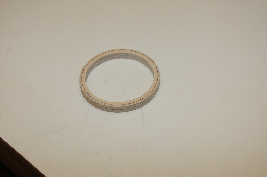
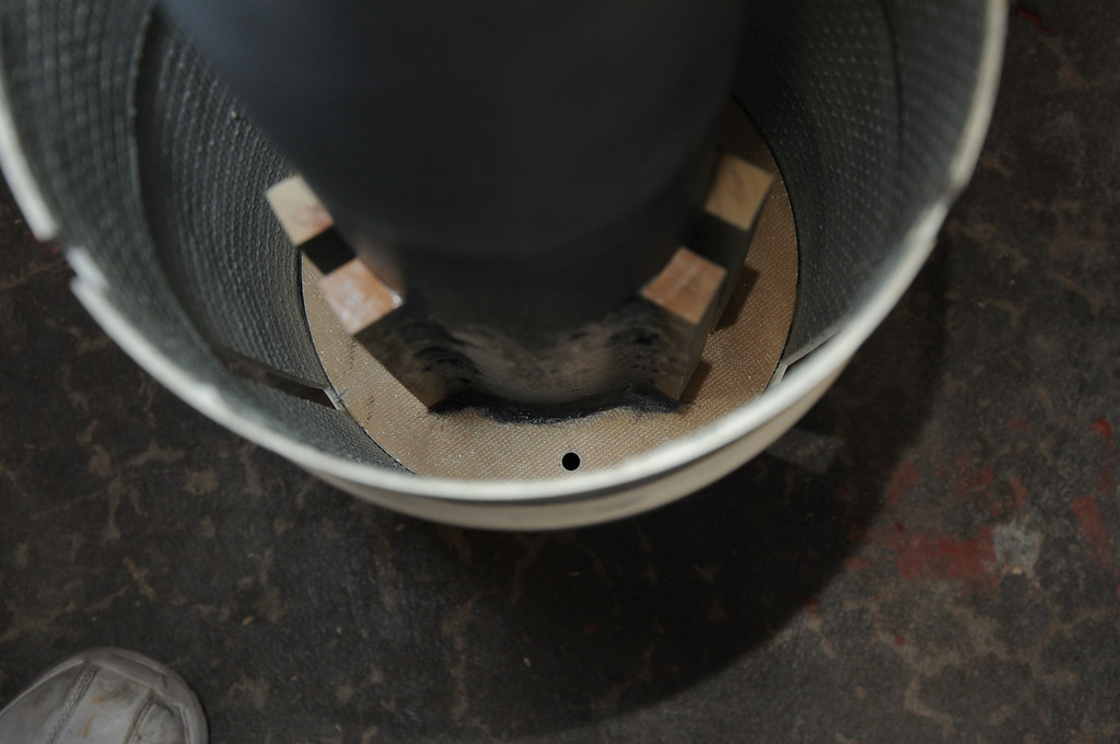
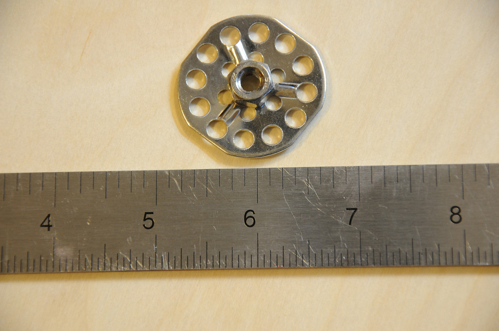
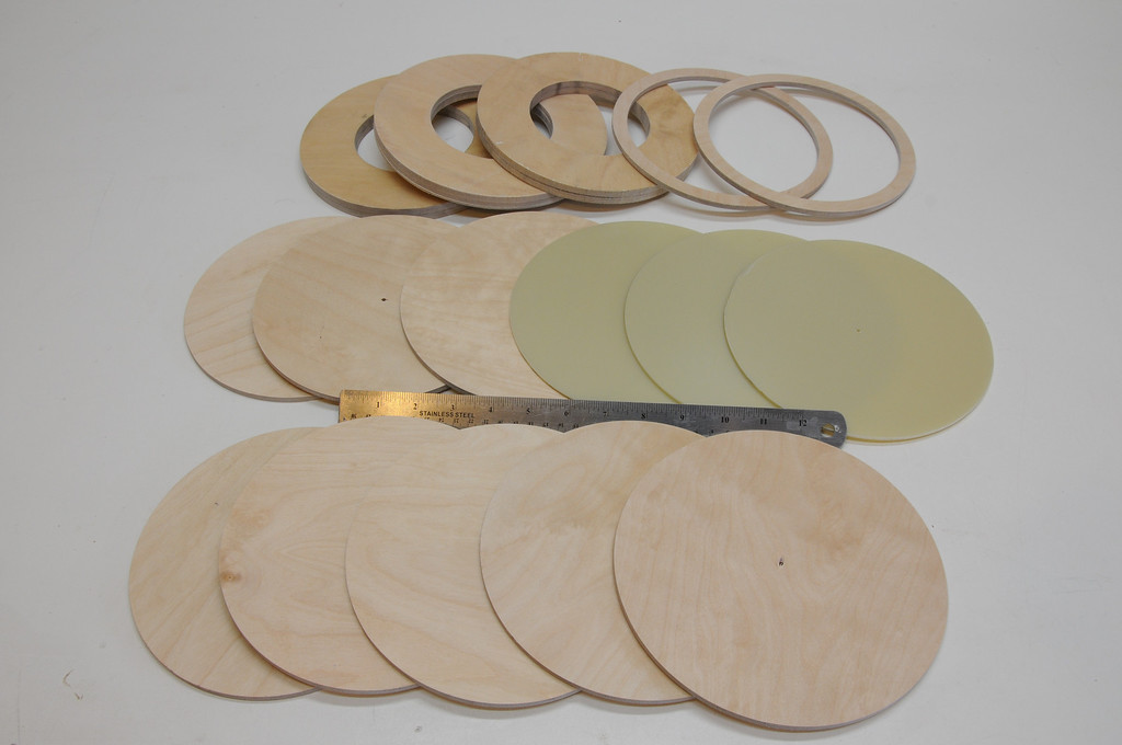
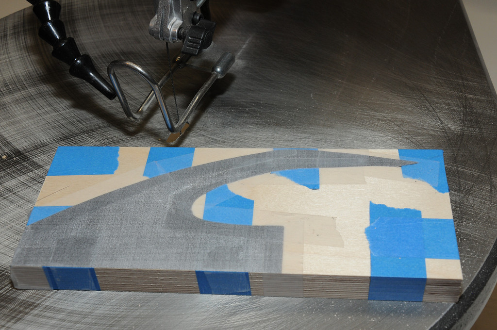
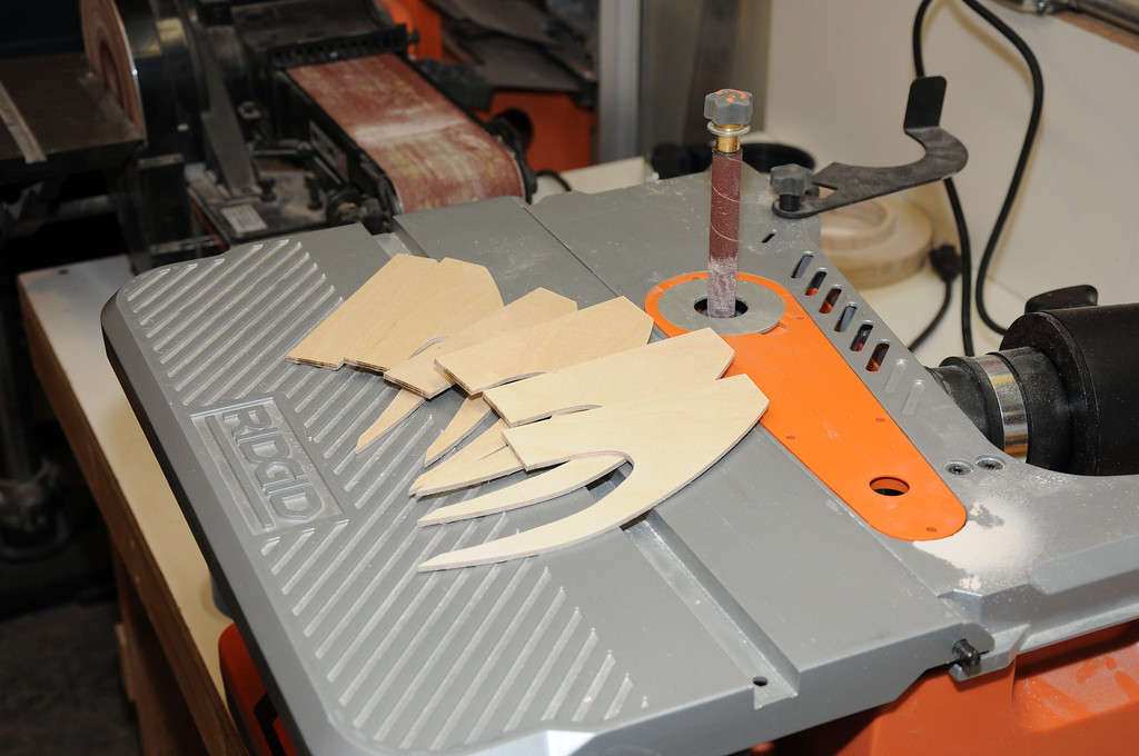
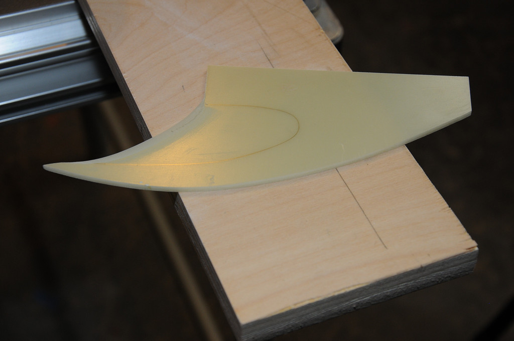
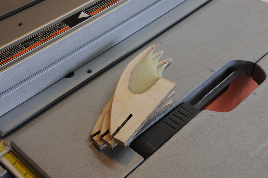
The pocket is constructed of hardwood square stock. As this photo shows, the square stock is not a particularly suitable shape for the 4" diameter motor tube.
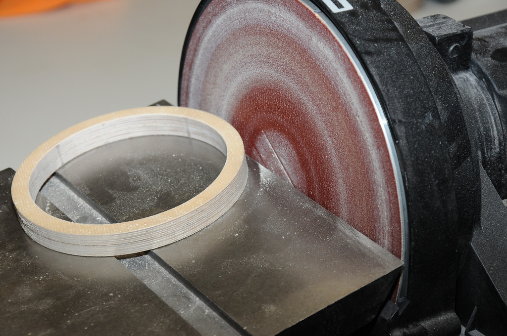
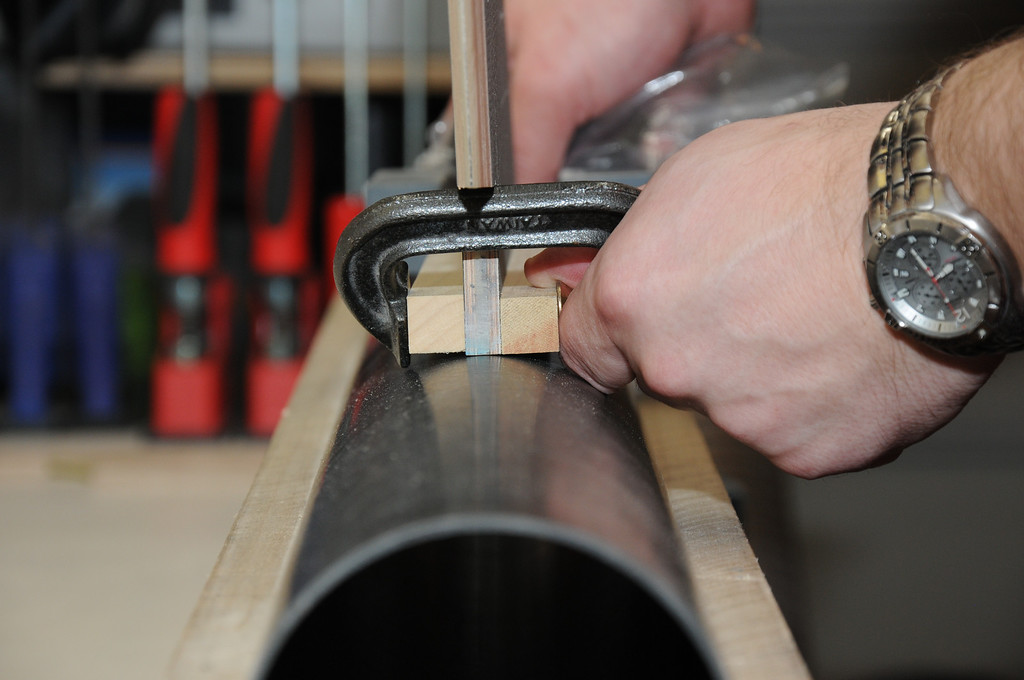
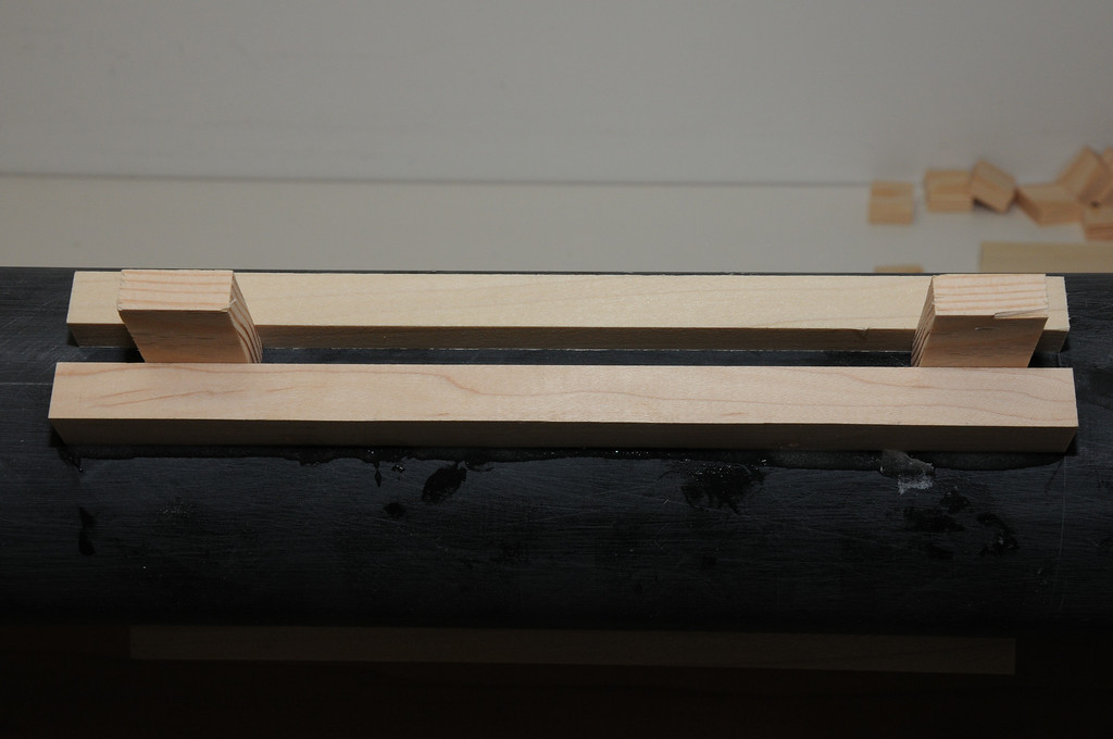
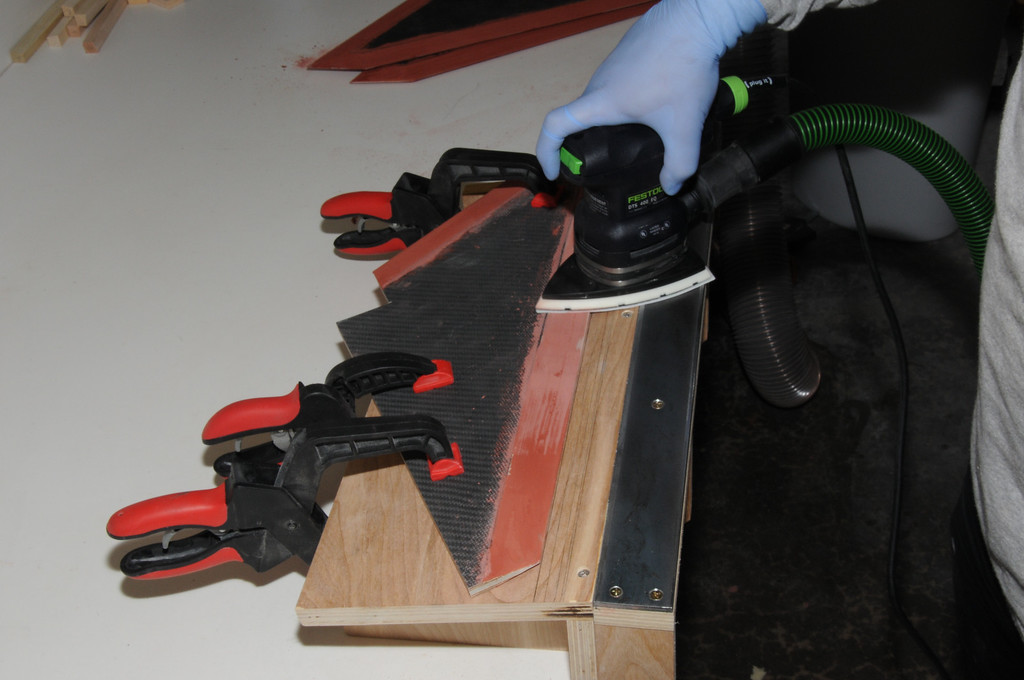
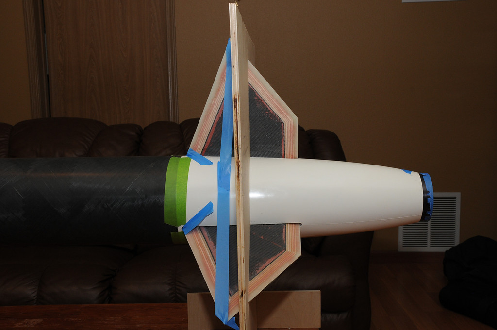
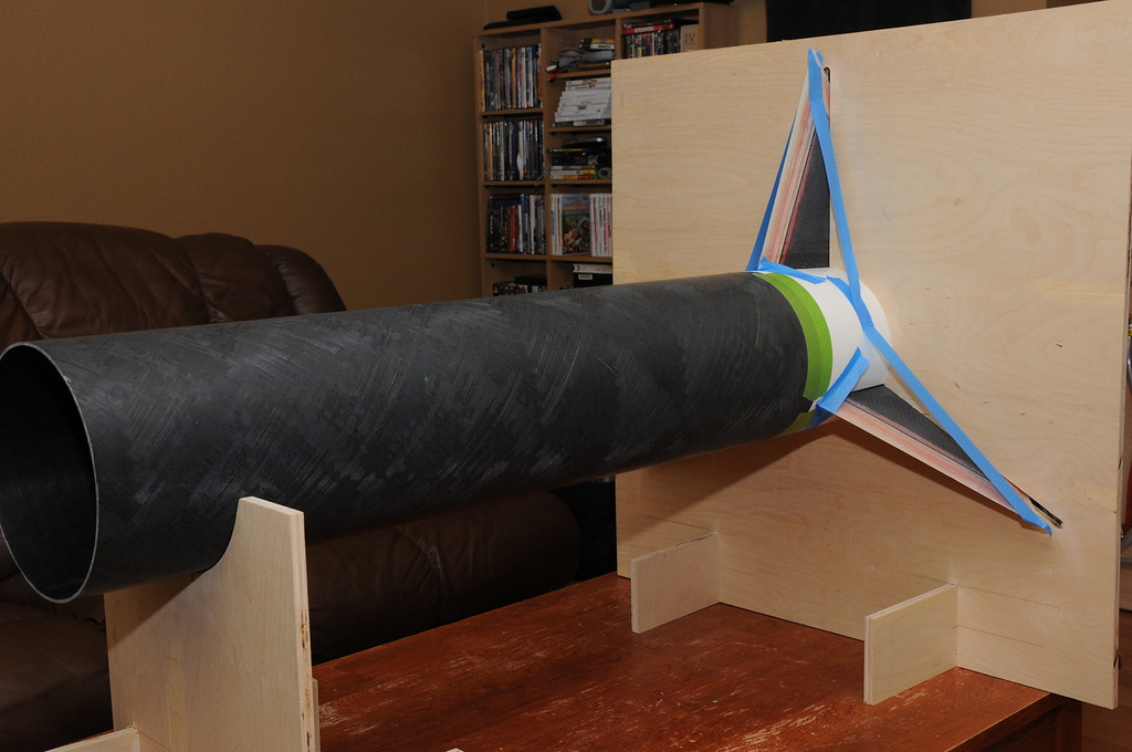
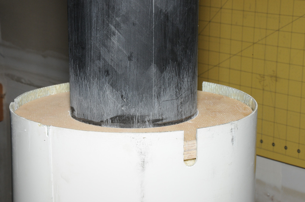
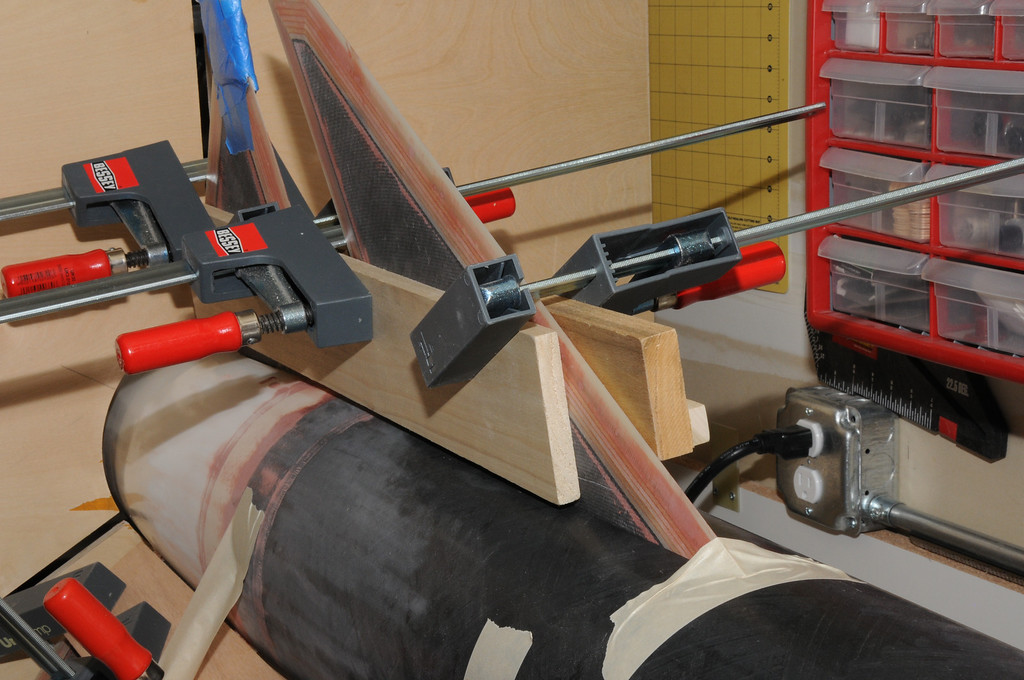
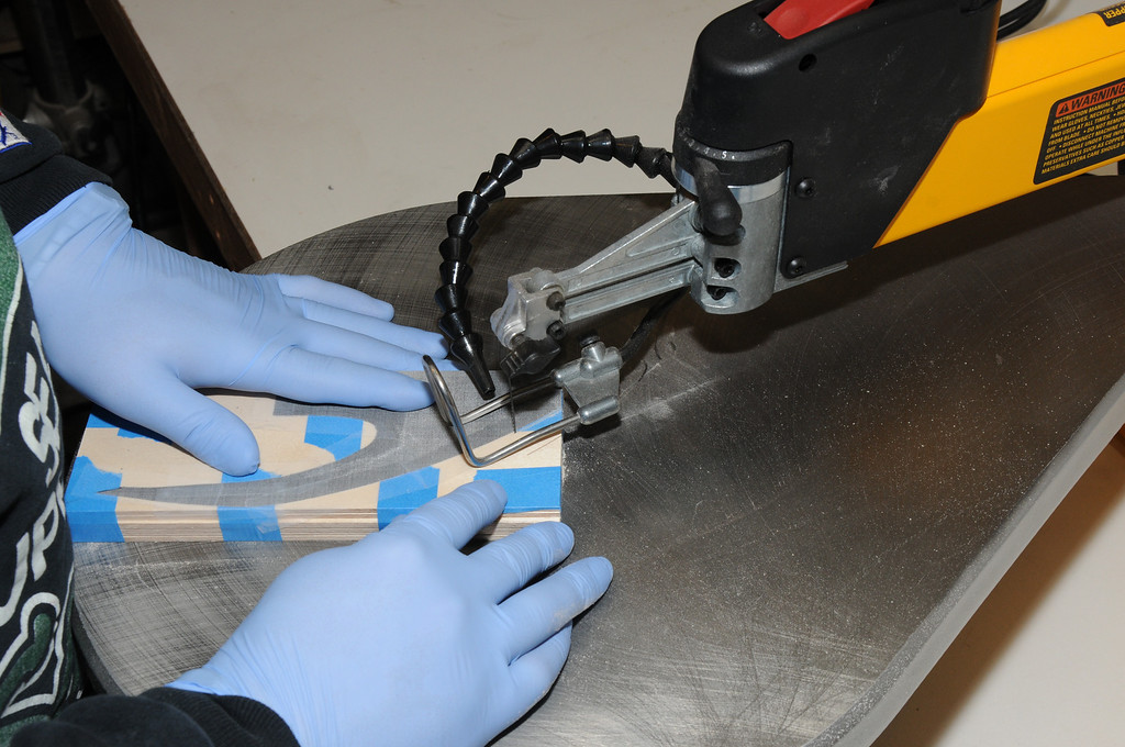
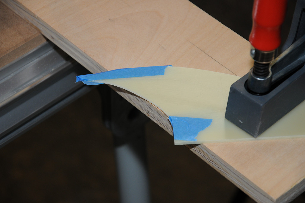
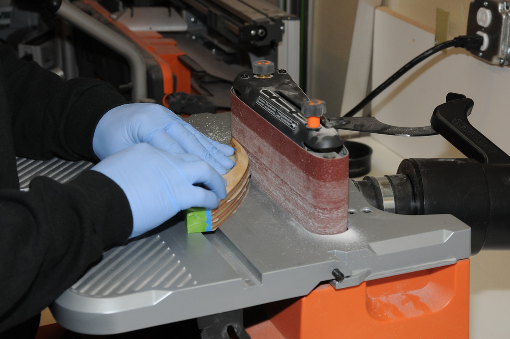
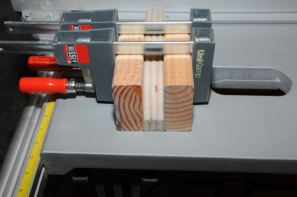
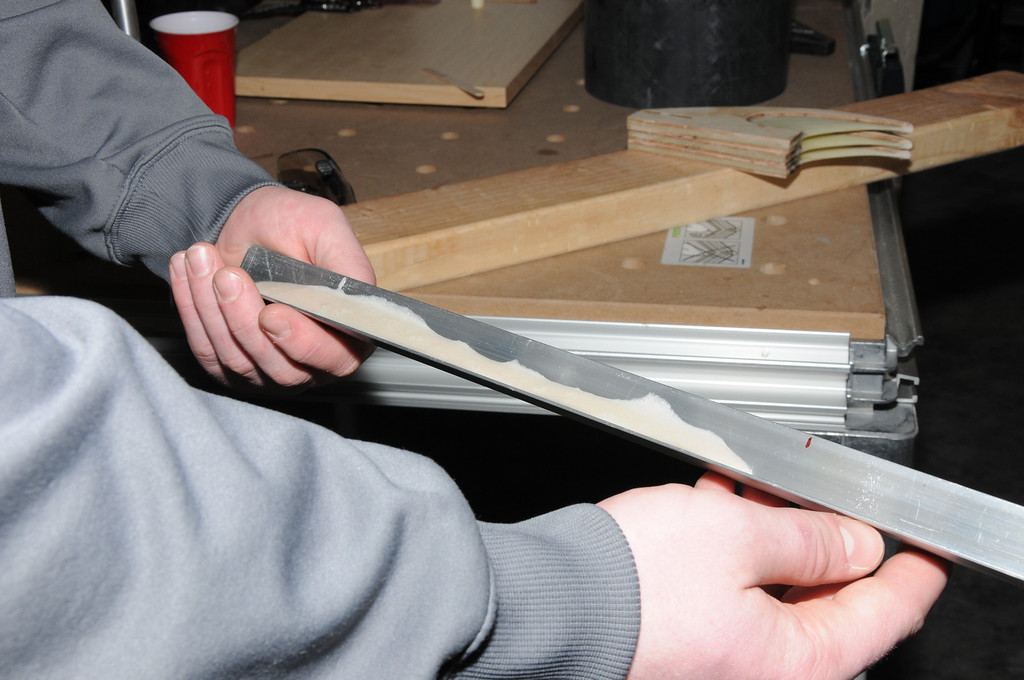
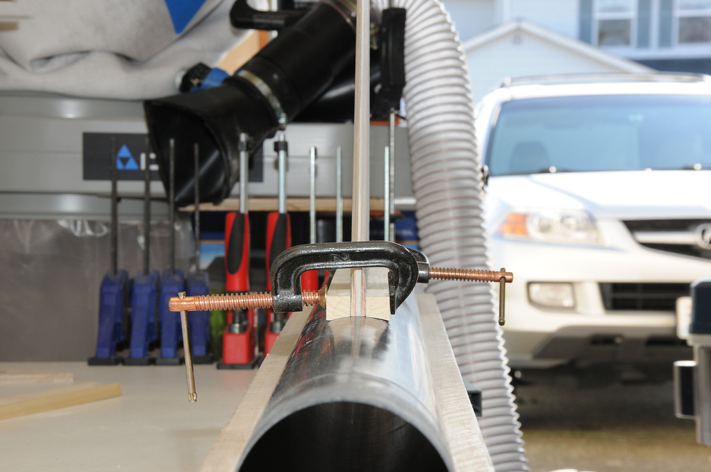
To form the square stock to the motor tube, I clamped a scrap piece of fin material between two pieces of stock cut to the proper length for the aft fins. Because I did not want to sand down the root edge of the scrap material (which would have been a ton more work), I elevated the fin stock and clamped the assembly tightly. This provided proper spacing while assuring I was only sanding the square stock and not the fin edge.
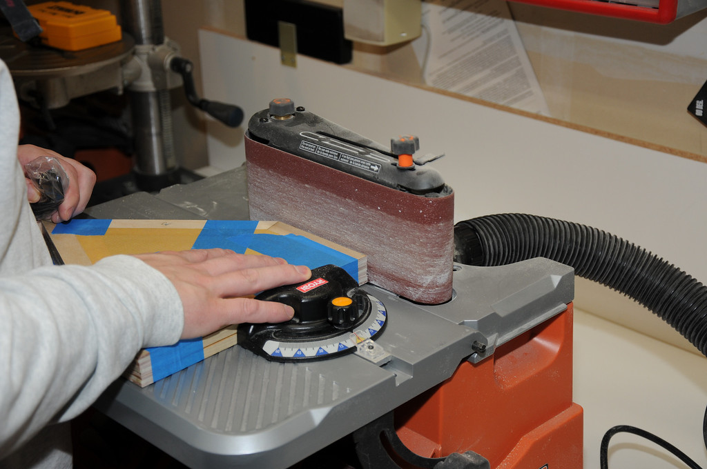
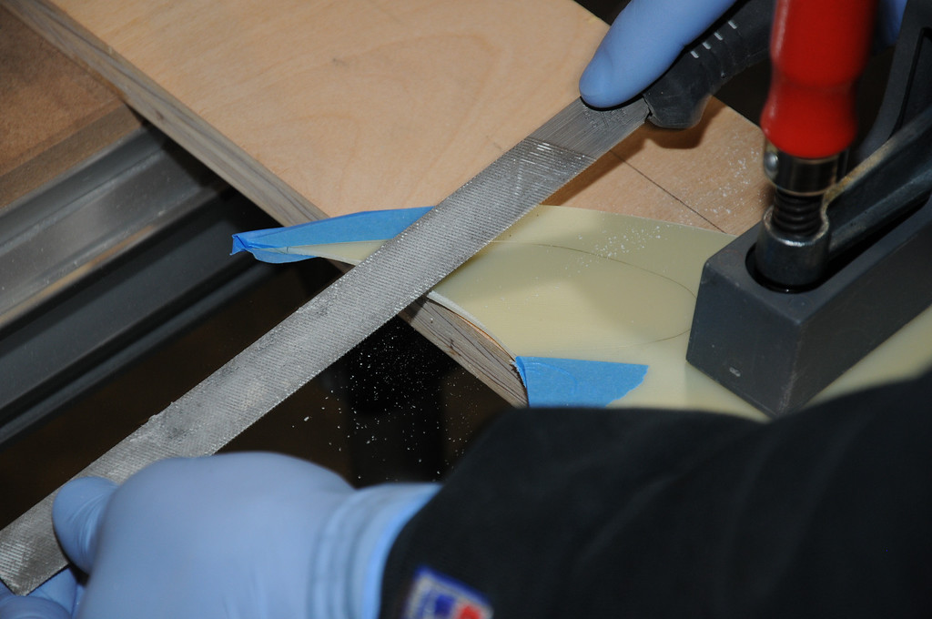
The entire assembly was then sanded along the motor tube wrapped with 60 grit sandpaper. This was more work than I anticipated and I decided that next time, a softer wood like basswood would work just fine and be easier to sand.
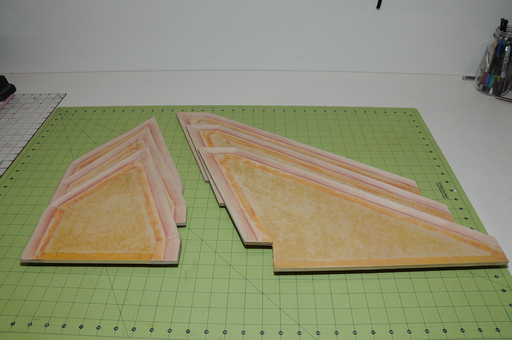
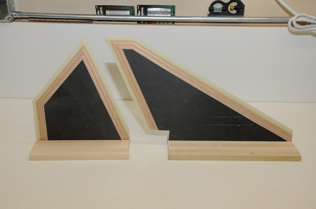
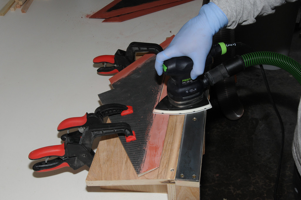
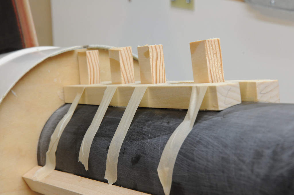
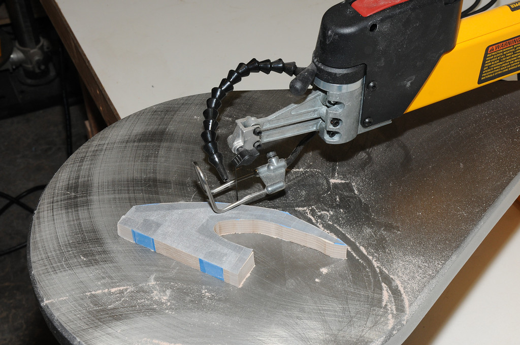
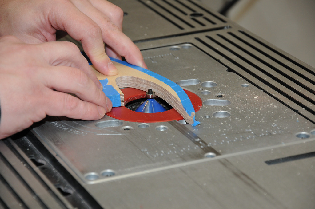
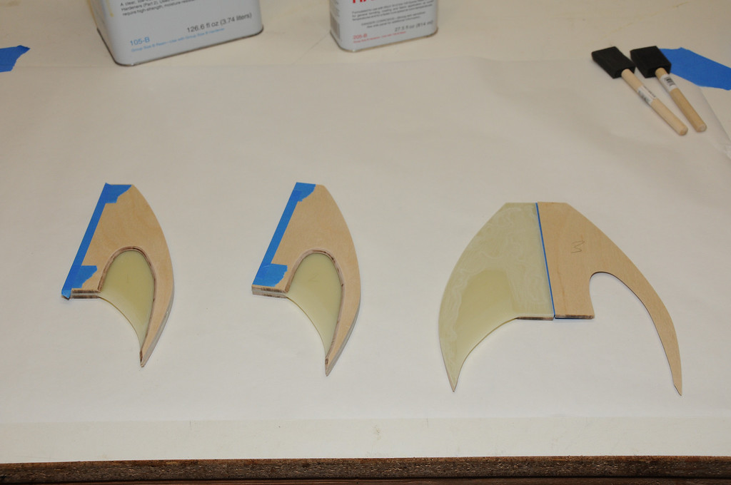
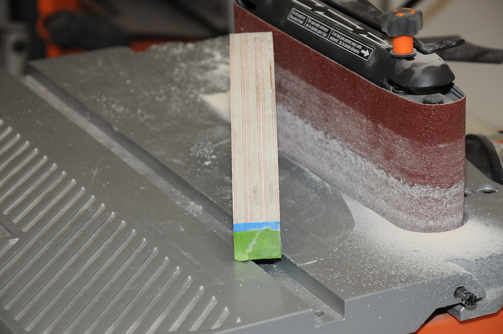
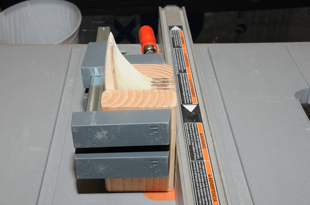
This photo shows a fin with the two formed pocket pieces held on either side. The sanding produced a much better fit. Each pair of stock pieces was sanded together and labeled to theoretically provide the best fit when making the pockets.
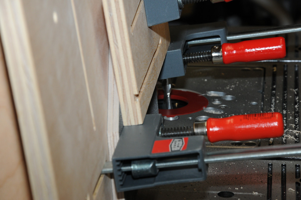
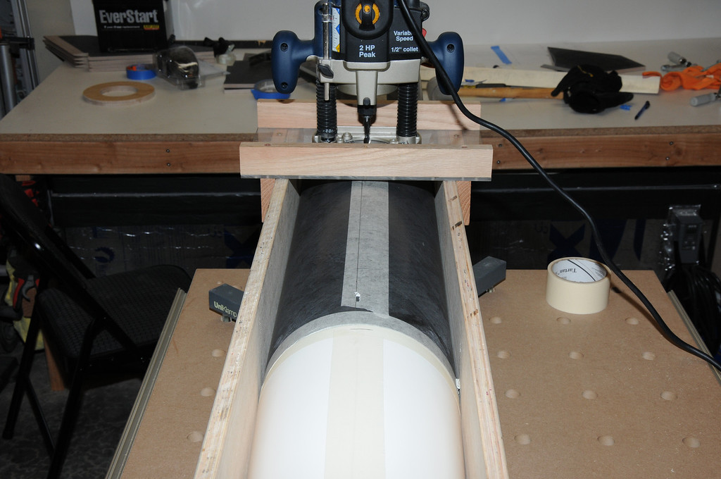
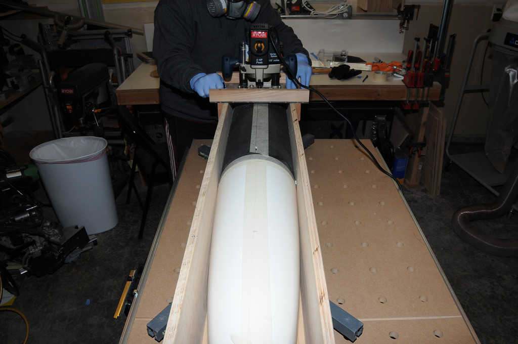
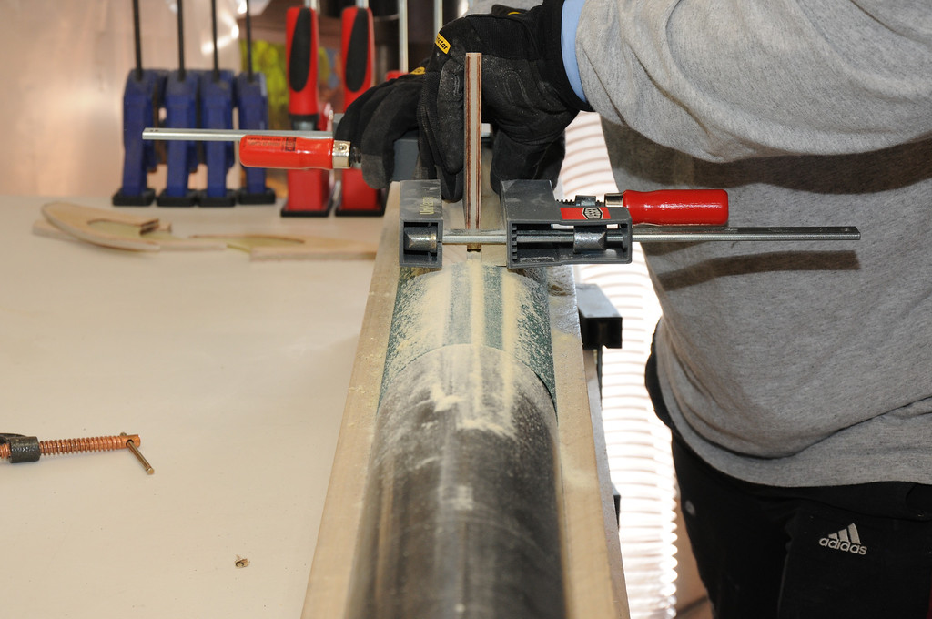
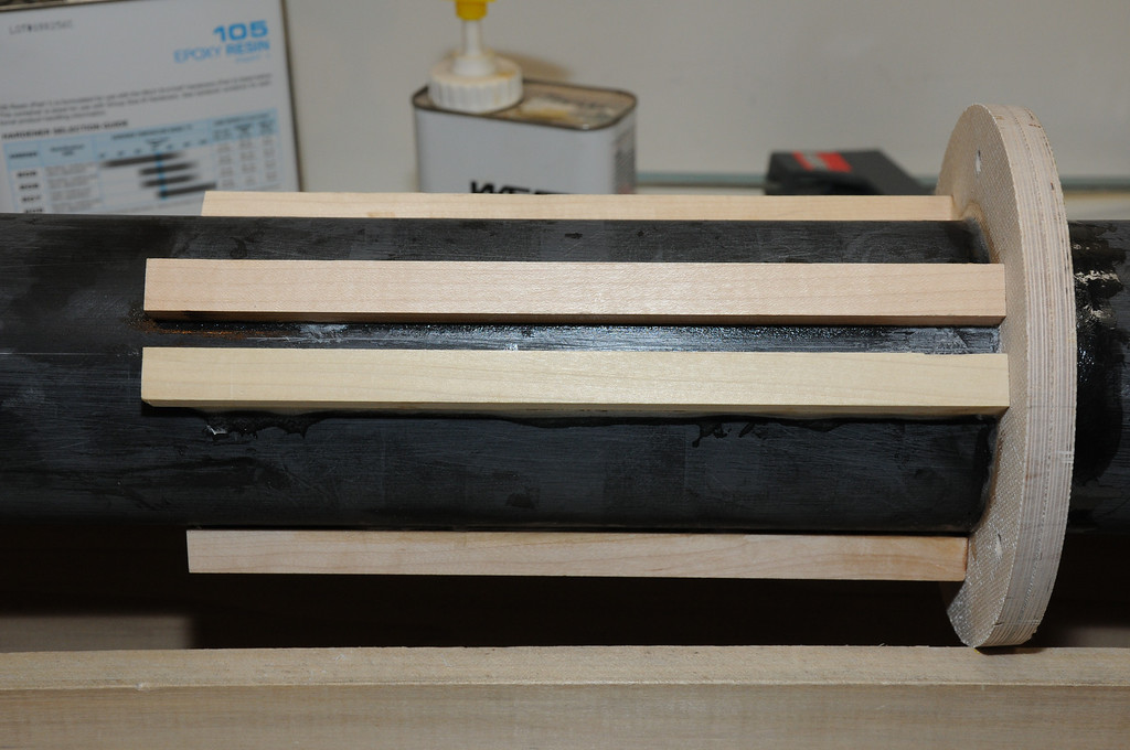
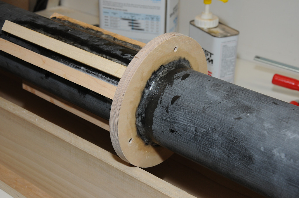
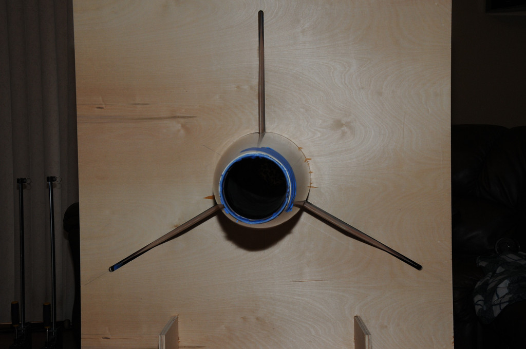
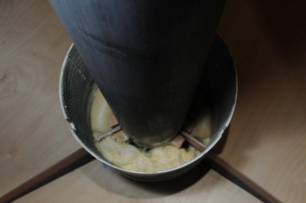
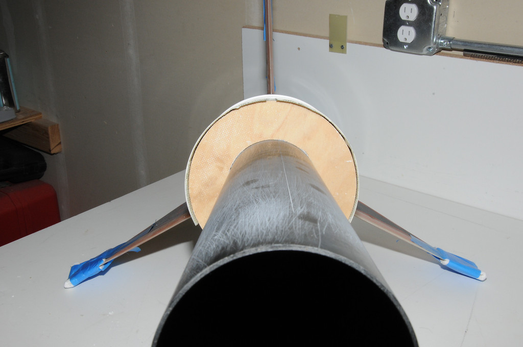
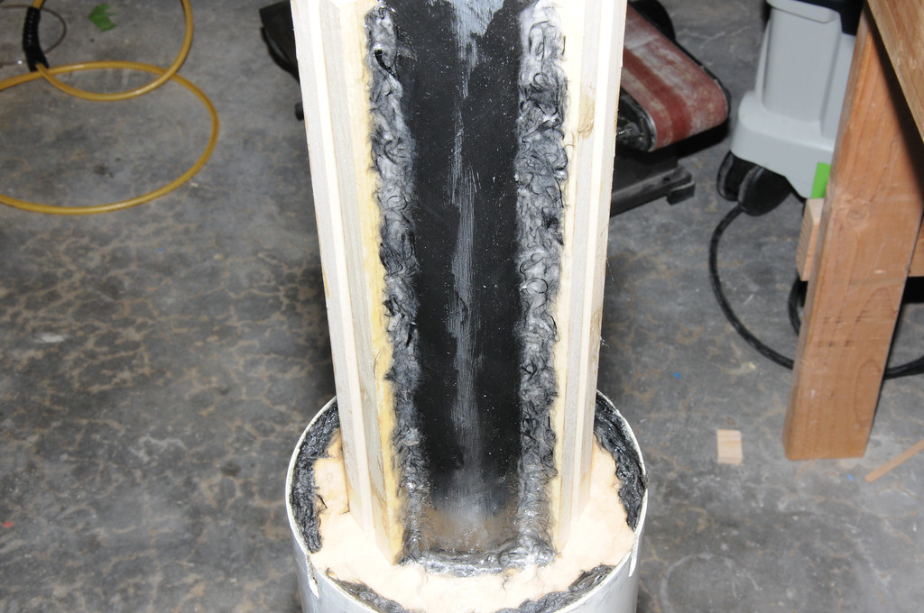
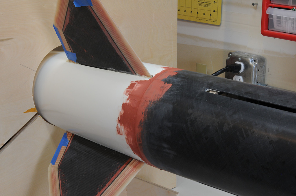
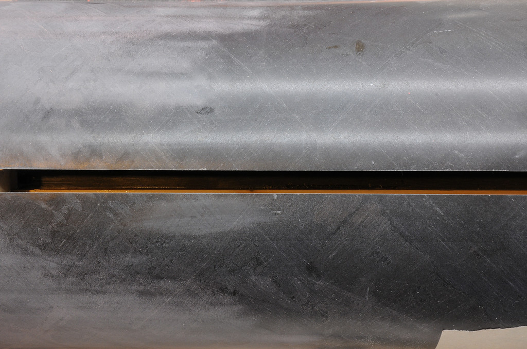
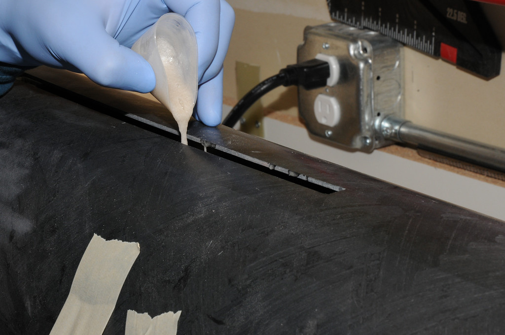
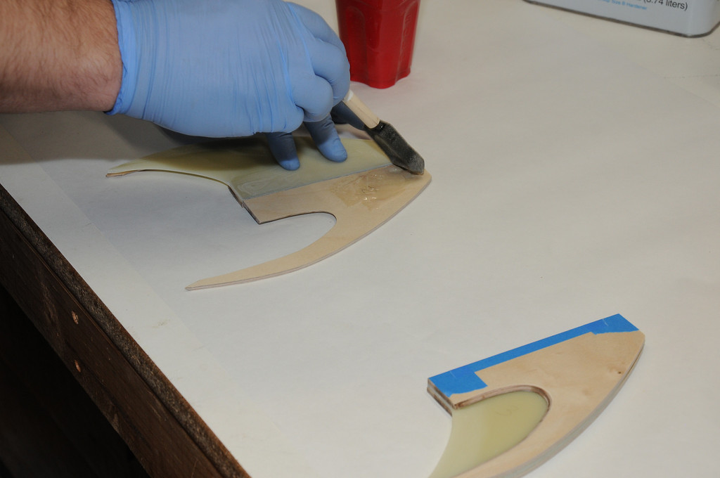
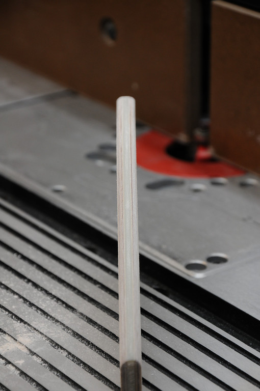
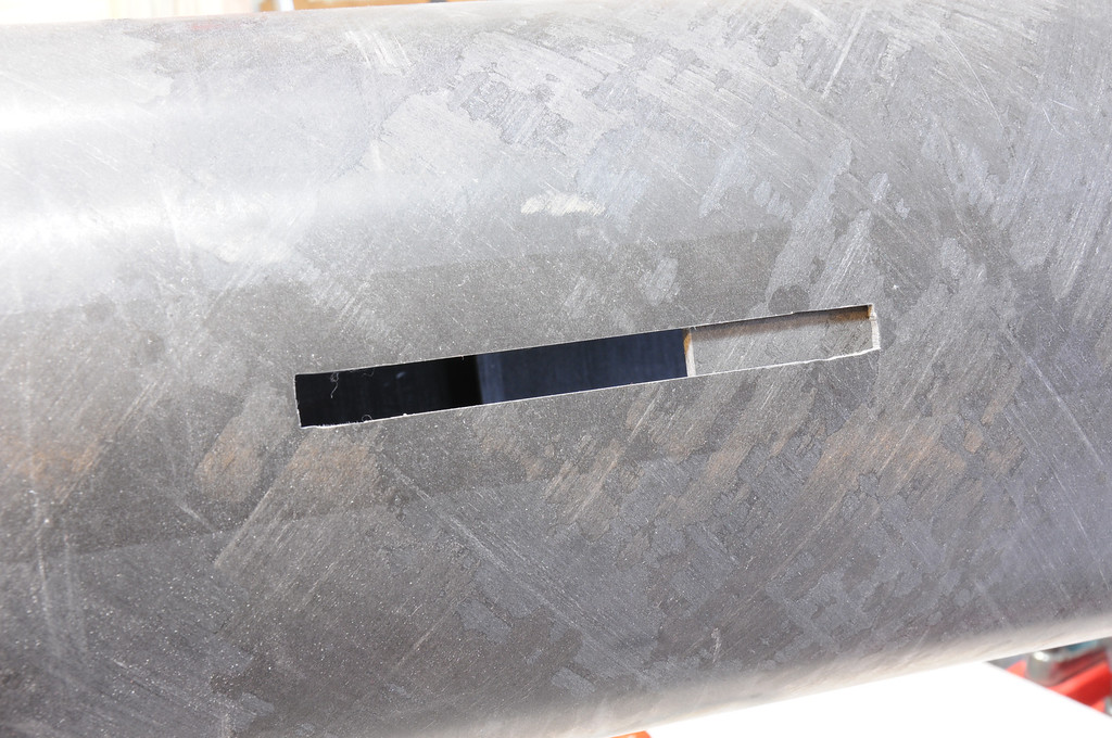
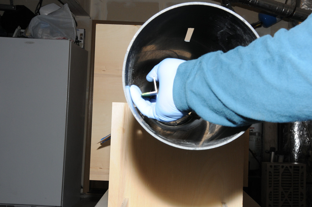
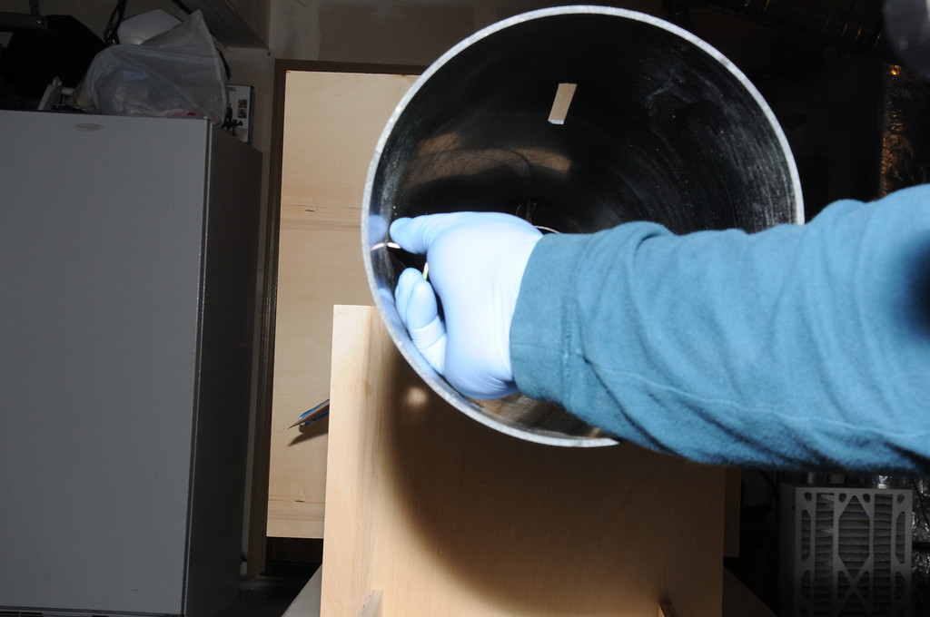
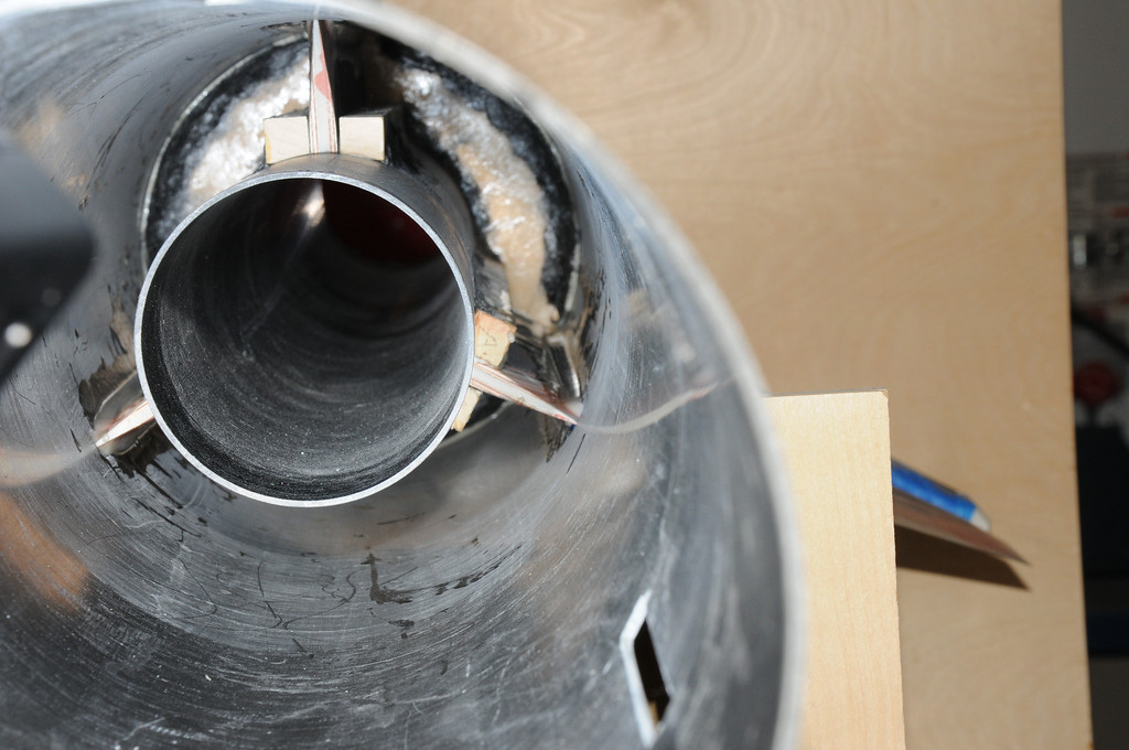
Here, I have begun to form the pockets. This photo shows several things: First, the line inscribed down the length of the motor tube. I use this instead of marker or pencil because those are very difficult to see on the black tubing. An awl run along a piece of angle aluminum makes a much easier-to-see line. Second, I have placed one side of each fin pocket on the motor tube right along the reference lines. The other sides are placed in relation to the first pieces once the epoxy dries. Finally, this photo shows the dry-fit aft fin aft centering ring with holes drilled in it. These holes allow the injection of expanding two-part foam into the aft portion of the boat tail. I did this to provide support for the cone itself, not so much for added strength of the fincan pieces.
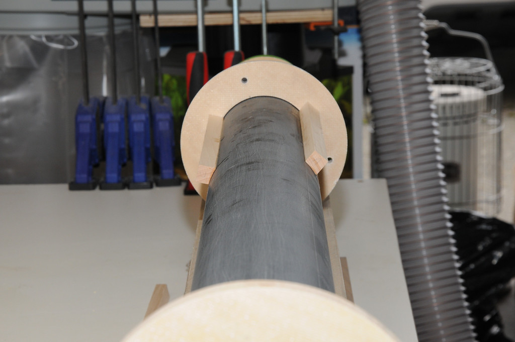
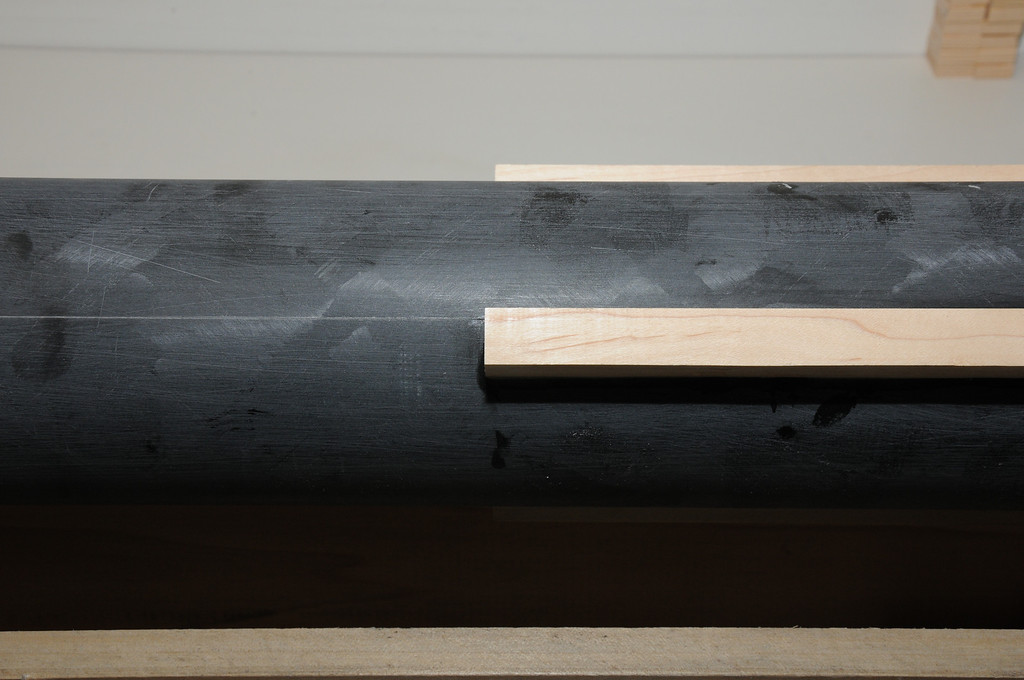
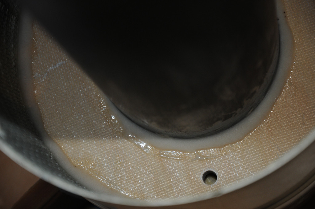
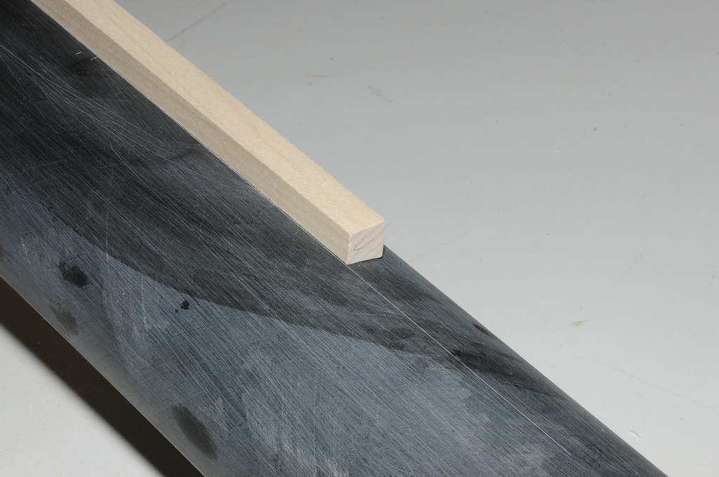
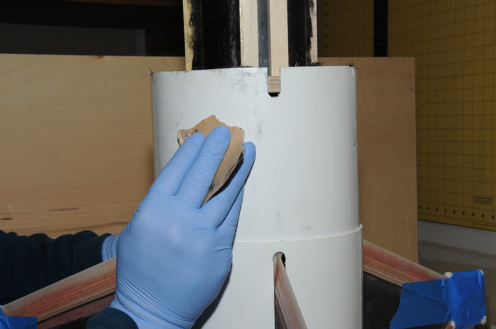
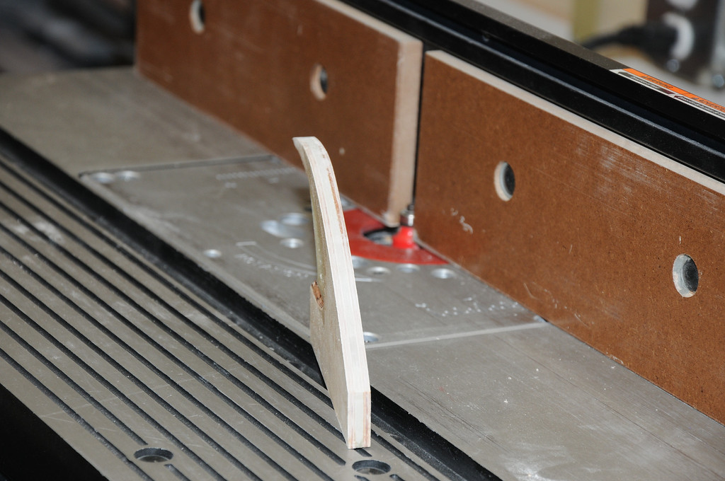
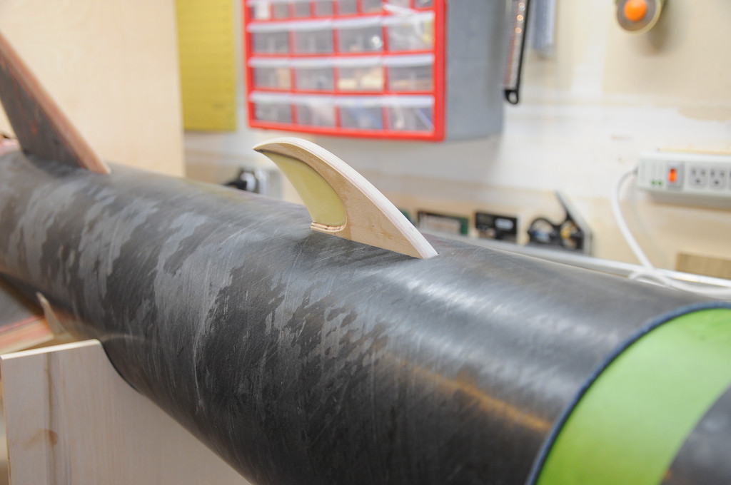
This photo demonstrates how well the scribed line shows up on the black tube and shows the alignment of one side of the pocket along this line. The fin will be placed above the piece of stock in this photo, with one edge right along the scribed line.
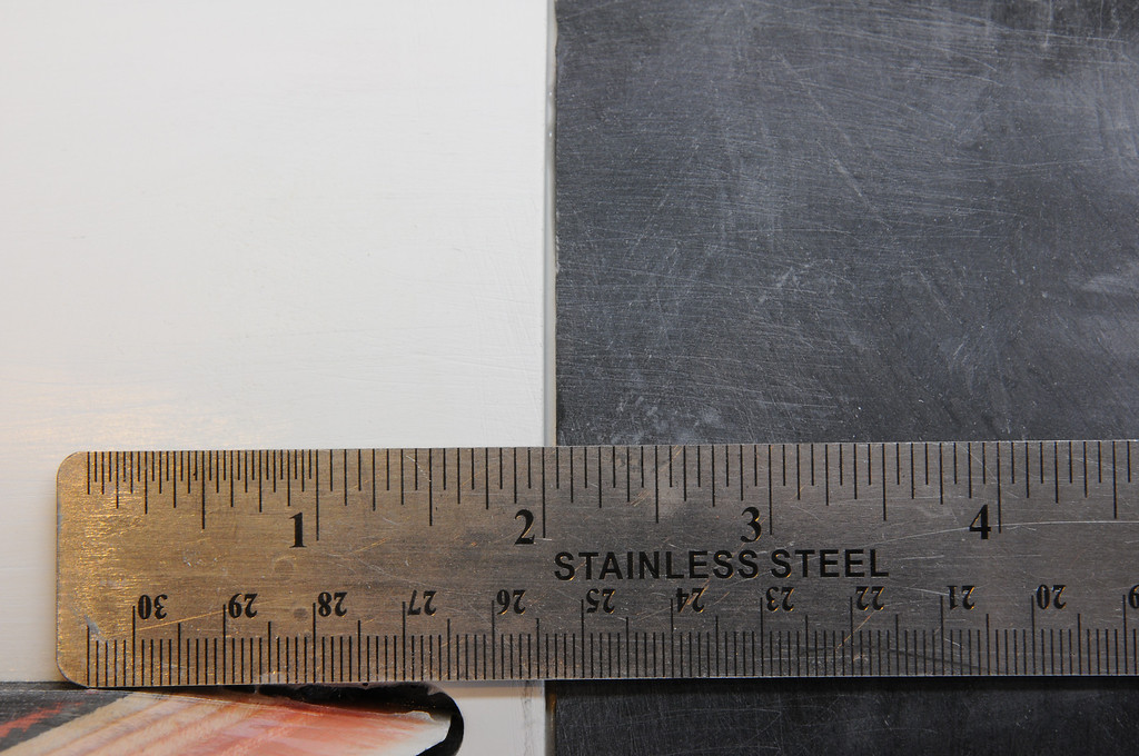
In order to be maximally effective, the pocket should be a bit wider than the thickness of the fin. This allows a thin layer of epoxy on the root edge and along the joint between the face of the fin tab and the fin pocket.
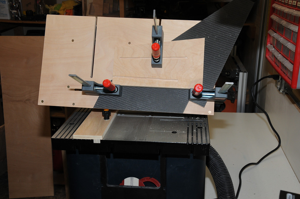
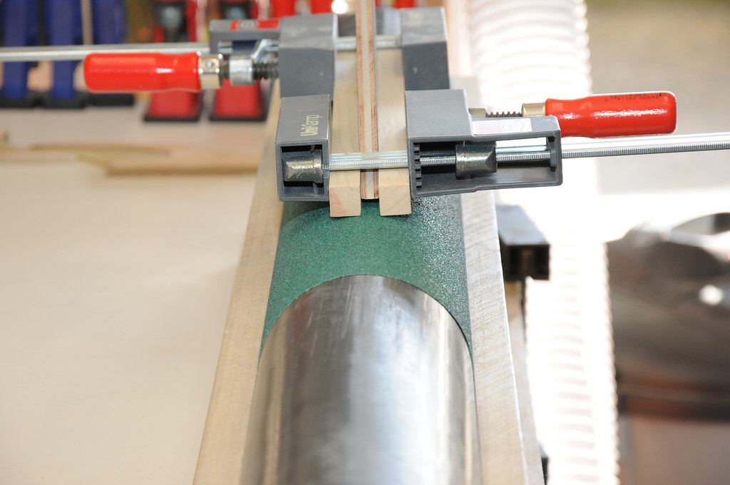
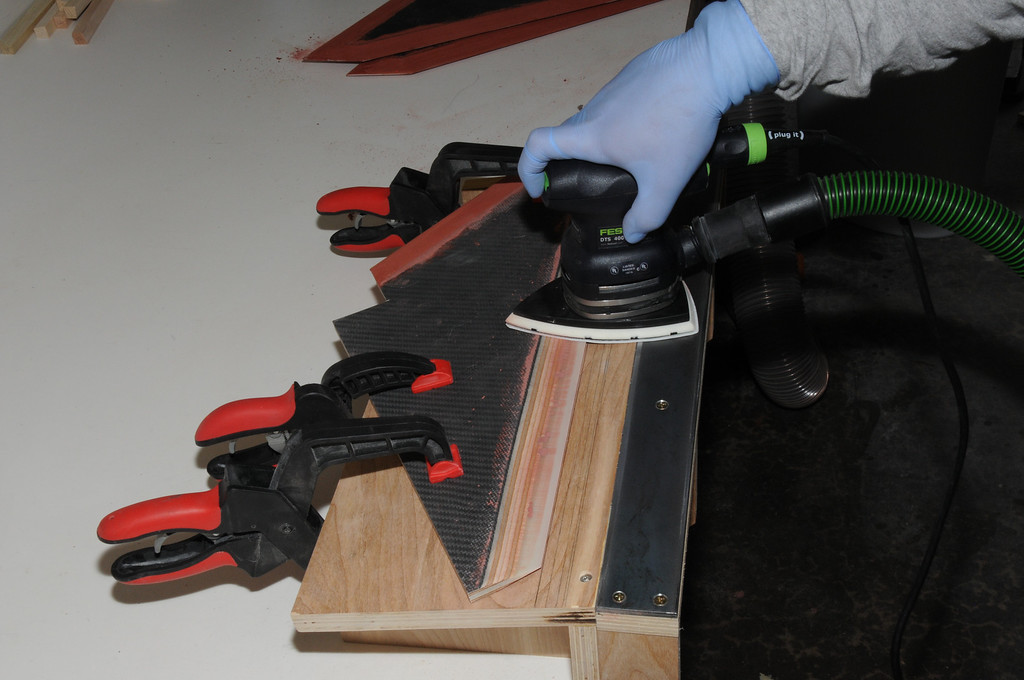
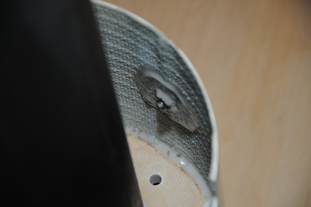
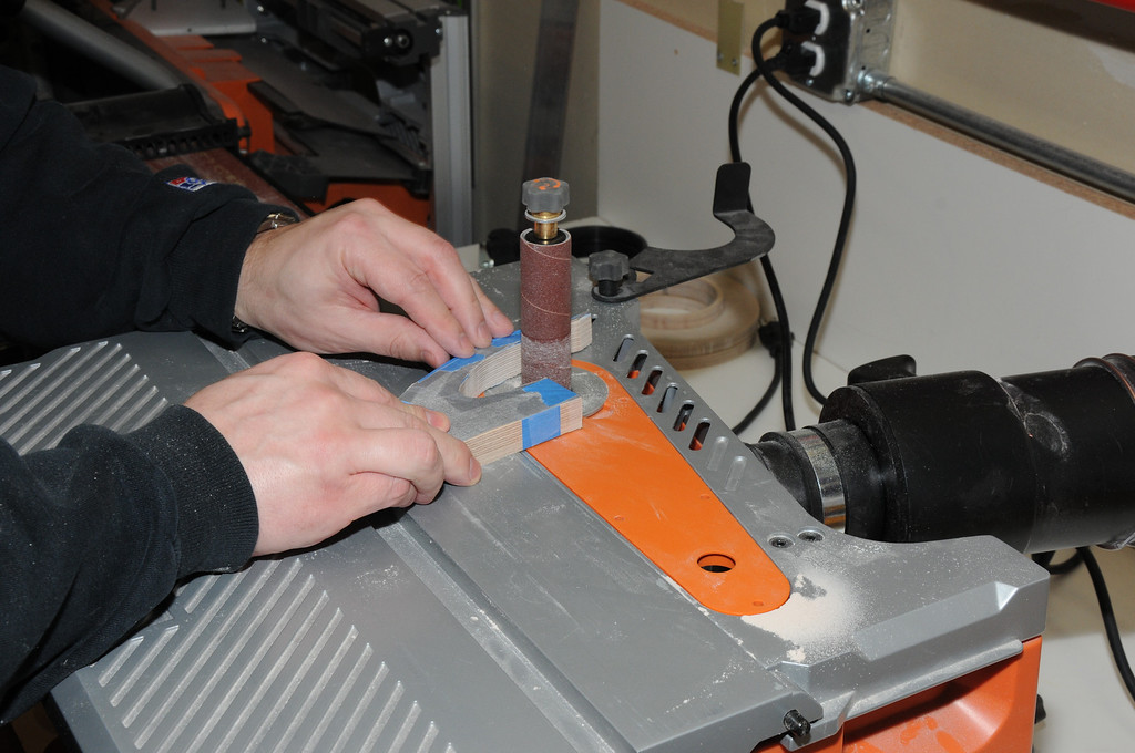
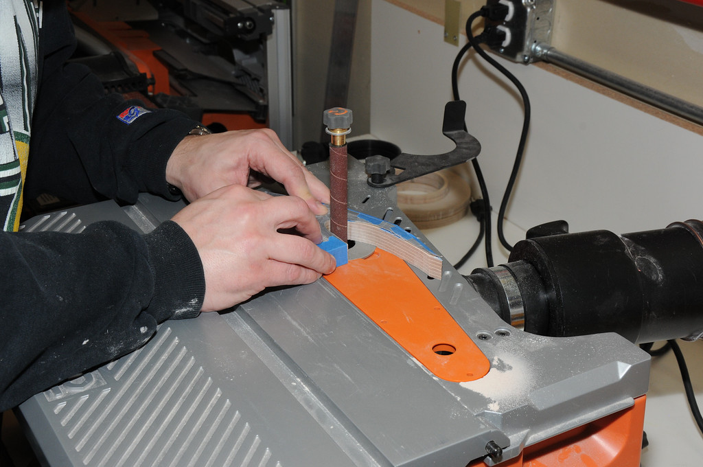
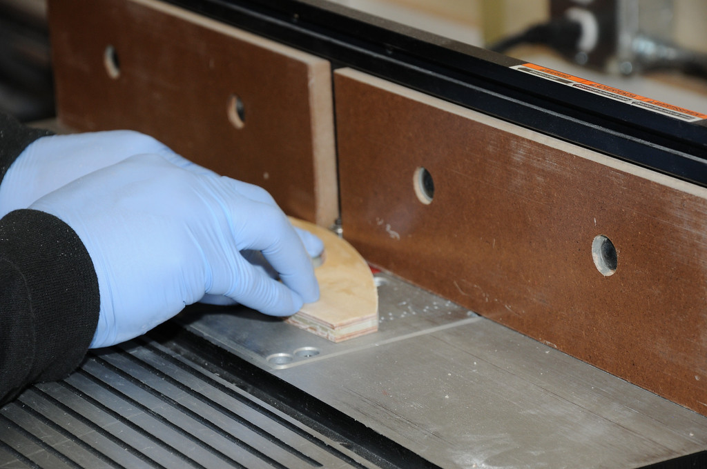
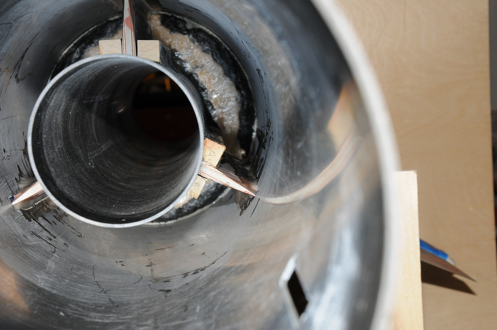
To produce pockets of the correct width, spacers were made by running scrap material through the planer until it was the correct thickness, then cutting it into several sets of spacers. This photo shows one pocket with the spacers in place, ensuring that the pocket edges were parallel and properly spaced to accommodate the fin tab.
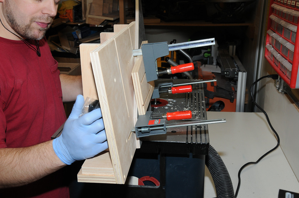
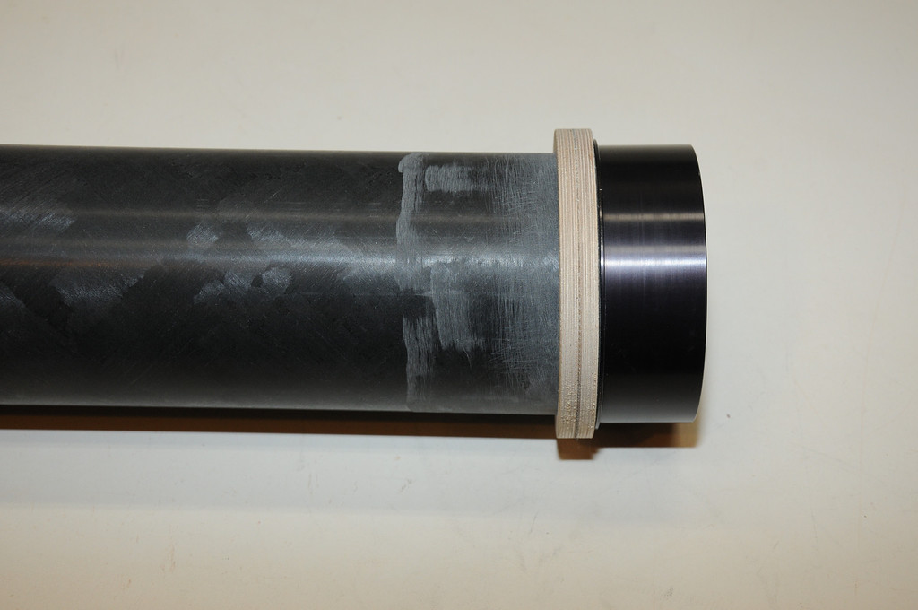
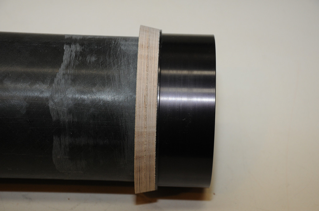
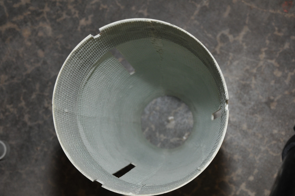
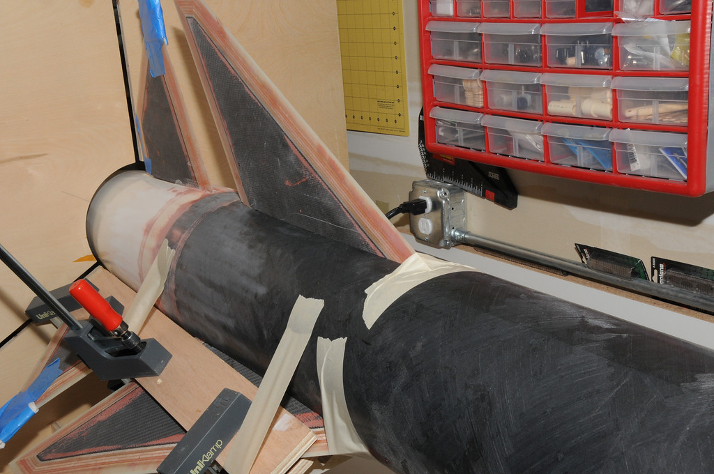
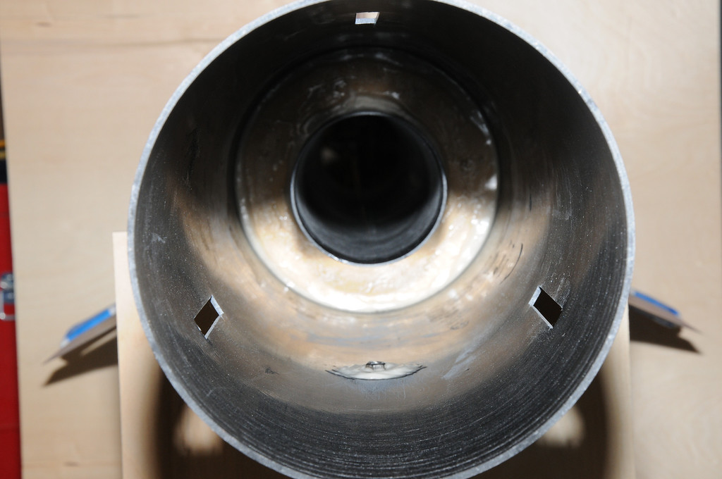
After forming all three aft fin pockets, the aft fin aft centering ring was epoxied into place, taking care to not allow excess epoxy to get inside the fin pockets, which would interfere with correct seating of the root edge.
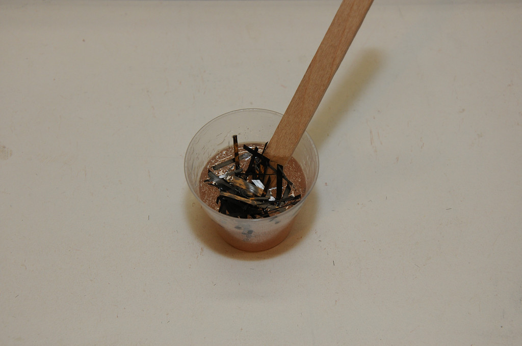
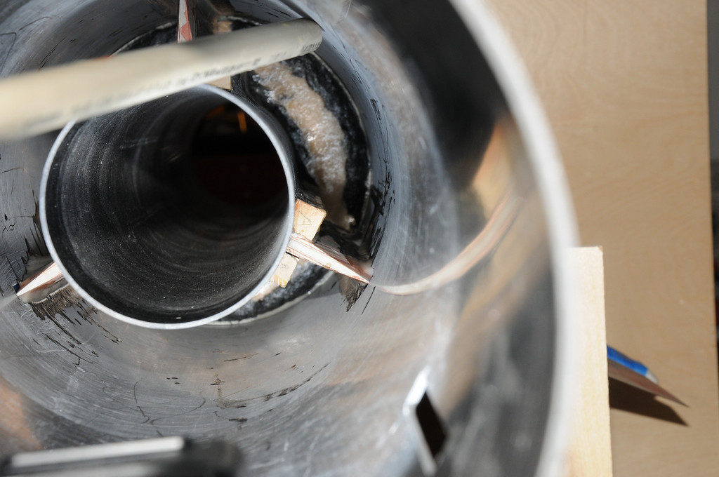
Because this portion of the rocket will not be exposed, I elected to use chopped carbon for the fillets. I took some leftover scrap CF from the fabric used to cover the fins and chopped it into short pieces. A pinch of this was placed in mixed epoxy.
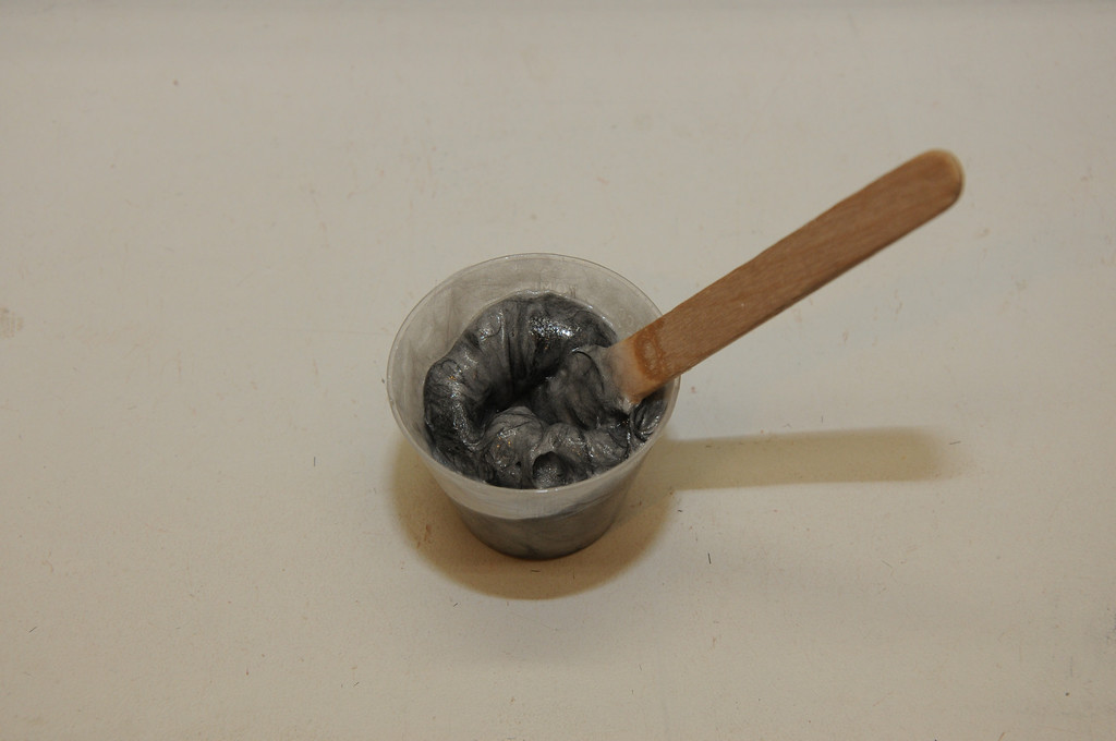
A little bit of this goes a long way and turns into a hairball pretty quickly.
I then slopped the nasty looking mess along the aft ring/motor tube joint and on the outside fin pocket/motor tube joints. As it is my intention that no one will ever see these joints again, I wasn't particularly concerned with cosmetics. Strength is the goal here.