How to square large fiberglass tubes

The Rocketry Forum

Help Support The Rocketry Forum:

This site may earn a commission from merchant affiliate links, including eBay, Amazon, and others.

phyzzld

Well-Known Member
TRF Supporter
Joined
Aug 18, 2017
Messages
99
Reaction score
30
I am starting work on my first 6 inch fiberglass kit. After checking the tube ends for square I found they need a little work. On smaller diameter tubes this is no big deal but thought it may not be so easy on this one. So I thought I would see what methods other members use.

Thanks,
Jeff
 
If the tube is too large to fit in my power miter saw I just slip the nose cone in or slip two body tubes together with a coupler, mark the high spots and knock them down with sandpaper on a block or a file.
 
If the tube is too large to fit in my power miter saw I just slip the nose cone in or slip two body tubes together with a coupler, mark the high spots and knock them down with sandpaper on a block or a file.

My problem is that all the tubes are a bit off. If I can get one end squared then that is a great idea. Thanks.
 
My problem is that all the tubes are a bit off. If I can get one end squared then that is a great idea. Thanks.

When you turn two tubes together with a coupler you can easily see the high spots on both. There’s no problem telling the difference.
 
I haven't tried it myself, but I have read that if you twist and grind two tubes together on a coupler, they will self-square.
 
get a piece of masking paper or something similar and wrap it around the tube. tape one end to the tube, pull it tight around the tube and tape it so the top edge of the paper is even. perfectly straight edge to cut/sand to.
 
If the tube is too large to fit in my power miter saw I just slip the nose cone in or slip two body tubes together with a coupler, mark the high spots and knock them down with sandpaper on a block or a file.

+1
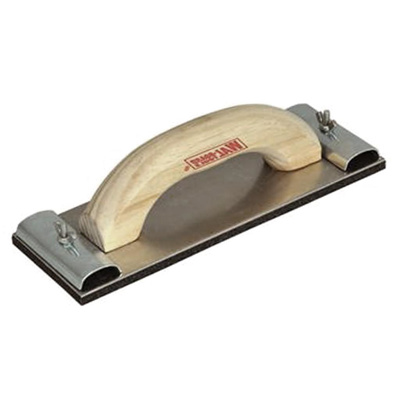
When I built my Formula 150 I had to square the end of a 6" tube. I used a big drywall hand sander with 120 grit sandpaper and that worked well.
w-wbhs66_1.jpg
 
get a piece of masking paper or something similar and wrap it around the tube. tape one end to the tube, pull it tight around the tube and tape it so the top edge of the paper is even. perfectly straight edge to cut/sand to.
If I couldn't jig it in the lathe (and use a Dremel as a toolopost grinder) to get it square I would do this ^. Works surprisingly well. You just need a big sheet of paper and then wrap it snugly on the airframe.
 
I haven't tried it myself, but I have read that if you twist and grind two tubes together on a coupler, they will self-square.

If you buy the tubes from the same manufacturer, the chances are all the tubes were cut on the same miter saw and received the same error. If you rotate the tubes end to end, eventually the high spot on one tube marries to the low spot on the other and vice-versa. This might be the phenomenon that has been seen.
 
If you buy the tubes from the same manufacturer, the chances are all the tubes were cut on the same miter saw and received the same error. If you rotate the tubes end to end, eventually the high spot on one tube marries to the low spot on the other and vice-versa. This might be the phenomenon that has been seen.

This is what I do... Then drill for shear pins and add witness marks. If there's still a little gap, pressure against the other tube and quick rotations to grind the tubes against each other lessens the gap. Just mind the dust...
 
V blocks and tube rotation are your friend. I know you said no jig, but they can be as simple as scrap 2 by 6 cutoffs with v's cut in them. shouldn't take more than a few minutes to make.
 
That's the problem with using miter saws. The solution is to use your miter saw differently. You use a stop block on one end , plunge just through the tubing wall, then rotate the tube all the way around. Perfectly square cut.
 
And never forget that the miter saw is responsible for more lost fingers than any power tool.
 
My e-z way... I wrap a length of parchment paper around the tube, match up the edges to make it straight, and tape. Then move it up to the edge, and mark all the way around with one of those large tip magic markers. Then sand away all the marks. YMMV.
 
Pretty sure you are thinking of a table saw. Miter saws are much safer than table saws.

I’ve got a true story about the insurance manager from the company I worked at and his radial arm saw experience.
He cut off 3 fingers. Finding one of them he jammed it in the snow outside the shop and went back inside to find the other two. When he came out the dog was there and the finger was missing from the snow. He grabbed the dog and drove himself to the ER. While the doctors reattached the first two, his brother started driving the dog to a veterinarian, but on the way the dog regurgitated it in his brother’s car. His brother brought it to the ER where it was attached.
It turned out that the reattachment of the first two fingers didn’t succeed, but the one that had been gobbled down and regurgitated by the dog succeeded. The ER doctors kidded him that the marinade made the difference.
 
Radial arm saws have probably the worst rep of all shop tools, however since they are not as popular as they once were the tablesaw has taken the rep of one of the most dangerous shop tools.
 
Hoping this helps square up some 4” tubes I’ve got. The ID of the printed tube is just large enough to get it over the tube to be squared while allowing it to rotate without allowing it to wobble out of square. The sanding bar slips into the slot, although I’m considering a redesign as it’s a hard balance to have the slot wide enough to fit the bar in without the sandpaper sanding the edges out of square but tight enough to keep it from wobbling. I’ll probably draw up some new files at the hotel tonight.

I should be able to give it a shot when I get back home this weekend on some tube scraps.

Edit: Although, thinking about it, using the ID of the tube to square the sanding bar might work a little better, or be easier to print at least.
 

Attachments

  • B4C5FD13-693A-4B1D-8F25-A4F9C7288CD2.jpeg
    B4C5FD13-693A-4B1D-8F25-A4F9C7288CD2.jpeg
    78 KB · Views: 172
Last edited:
3D printing opens up so many more choices for jigging. It is a real paradigm shift. Nice work!
It’ll be nice if it works! :p

After the initial cost of the printer, most filament is pretty cheap. I’m really happy with Micro Center’s Inland PLA at 13$ shiped per kg. It’s great being able to make one off disposable tools with very little time and money invested. :D
 
Last edited:
Managed to go over the design. The over sized slot allows for the sanding bar to be slid back and forth to make better use of the sandpaper on it, rather than burning up one small section and having to replace it. I need to work on the coupler as it's a little loose, but after a quick sanding the tubes seem pretty square to me.
 

Attachments

  • IMG_5145.JPG
    IMG_5145.JPG
    91.1 KB · Views: 108
  • IMG_5147.JPG
    IMG_5147.JPG
    104.2 KB · Views: 125
  • IMG_5148.JPG
    IMG_5148.JPG
    76.6 KB · Views: 117
  • IMG_5154.JPG
    IMG_5154.JPG
    65.7 KB · Views: 113
Radial arm saws have probably the worst rep of all shop tools, however since they are not as popular as they once were the tablesaw has taken the rep of one of the most dangerous shop tools.

I had one until just a few weeks ago. Sold the beast to free up some room. It was the scariest tool in the shop.
 
Managed to go over the design. The over sized slot allows for the sanding bar to be slid back and forth to make better use of the sandpaper on it, rather than burning up one small section and having to replace it. I need to work on the coupler as it's a little loose, but after a quick sanding the tubes seem pretty square to me.

Do you have the STL for this please?

Am a little confused how the sanding pad moves
 
Do you have the STL for this please?

Am a little confused how the sanding pad moves
They're posted under my Level-2 build thread, I'm on my phone with terrible service, so I'll grab a link when I get a chance.


There's 4 #6 screws in the top bracket. Loosen them up and you can slide the bar back and forth to get to a fresh section. Or if you meant how it moves against the tube, you just spin the jig on the tube.

No worries dude I did find it just.

https://www.rocketryforum.com/threads/3d-design-constest-kc3knm.147558/

Am curious about the fin bevel as well.

If you can please post a video of both in action or PM me it. Would you share the STL for the fin bevel as well?
 
Back
Top