


MClark
Well-Known Member
As you state the Nike is a REAL motor, it was designed to be a rocket case and is made of steel. Doesn't compare to irrigation pipe.
I still would not use a seamed tube.
I still would not use a seamed tube.
When I get up the desire to get my L3, this is what I have been kicking around in a paper 4" rocket. My idea is to extend that concept all the way up. Essentially use couplers in between centering rings possibly held together with all threads. All glued into a body tube.
As you state the Nike is a REAL motor, it was designed to be a rocket case and is made of steel. Doesn't compare to irrigation pipe.
I still would not use a seamed tube.
This looks seamless https://www.onlinemetals.com/merchant.cfm?id=71&step=2⊤_cat=60 9" od 1/2" wall 6061 T6 extrudedI don't want to be a downer here but I would not use a seamed tube for a rocket motor of any size.
M
This looks seamless https://www.onlinemetals.com/merchant.cfm?id=71&step=2⊤_cat=60 9" od 1/2" wall 6061 T6 extruded
This looks seamless https://www.onlinemetals.com/merchant.cfm?id=71&step=2⊤_cat=60 9" od 1/2" wall 6061 T6 extruded
He said 7 1/2'Paul,
Yes, it does say "extruded". That particular tube is 6-61-T6 Aluminum / 9.00" OD / 8.00" ID / .500" Wall / 15.702 lbs/ft. / $1565.63
So, an 8ft length would weigh 125.6 lb. . . .
According to Chuck, his empty motor ( presumably with end closures ) weighs 90 lb.. He never mentioned its length, as I recall.
Dave F.
")
That’s a great link Paul. I’ll contact them about the seams.
To others cautious about the current casing having a seam trust me it’s being addressed.
Pressure-testing to 2000 psi and ensuring little heat transfers to the casing might make it viable.
I’ve got two of the best big motor builders in the country on this and won’t commit the casing to launch unless it passes all specs.
I do like the tube Paul posted. Extruded can be inferior to DOM due to variances in the ID.
An issue that can be worked around but it is a factor.
All your inputs are welcome of course. We look at everything.
Chuck C.
Burnsim is theoretical. Everything is perfect, grains all burn out at exactly the same time. It does not take into account erosive burning or manufacturing variations. By the core/throat ratio, this motor will be quite erosive. There will be a tail off in thrust as the bottom grain burns out first and the initial thrust will be higher than the sim shows..NOTE : I am very curious why it abruptly "cuts off" at 8.78 seconds, rather than showing the Burn Data all the way down to Zero Thrust. In other words, it is likely NOT an accurate Time-Thrust Curve but, rather, a "sampling" of some type. If that is the case, and the Burn Time is actually longer, increased performance, likely well above the 42,000 ft. AGL number may be the case, as well as extended time above Mach ( heating concern ).
View attachment 369778
We also need to integrate the motor data from Pat G's graph into the simulation program.
NOTE : I am very curious why it abruptly "cuts off" at 8.78 seconds, rather than showing the Burn Data all the way down to Zero Thrust. In other words, it is likely NOT an accurate Time-Thrust Curve but, rather, a "sampling" of some type. If that is the case, and the Burn Time is actually longer, increased performance, likely well above the 42,000 ft. AGL number may be the case, as well as extended time above Mach ( heating concern ).
Dave F.
Burnsim is theoretical. Everything is perfect, grains all burn out at exactly the same time. It does not take into account erosive burning or manufacturing variations. By the core/throat ratio, this motor will be quite erosive. There will be a tail off in thrust as the bottom grain burns out first and the initial thrust will be higher than the sim shows..


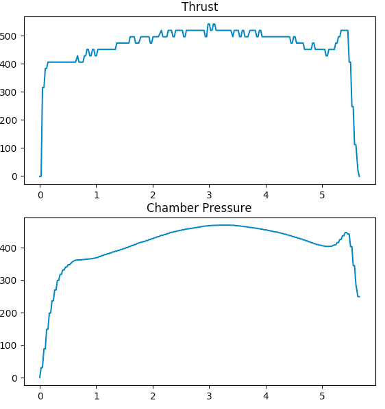
Though the motor obviously won't shut down that quickly, there is no reason to assume that motors must have a long trail off. The regressive thrust curves of many commercial motors are due to the erosive phenolic nozzles companies like Aerotech and CTI use, which have nozzle throats that constantly increase in diameter as the burn progresses. These motors typically feature progressive grain geometries, but the constantly increasing nozzle throat makes the overall motor regressive. Companies like Loki and most EX motor makers use graphite nozzles that do not erode. A constant nozzle throat diameter paired with a properly designed grain geometry can result in a very neutral profile as show in the burnsim output. If you don't believe me, check out some real results:
For this specific motor, though, there is no reason to believe that the thrust curve will be exactly as pictured. The high mass flux at startup indicates that there might be erosive burning near the ignition transient, meaning that the bottom grains will probably burn out before the upper ones. This would mean a longer shutdown period, but similar delivered impulse. Pat has been making motors much longer than I have, so I'm sure he's aware of these effects and prepared a burnsim model that he thinks will be useful. Until a test burn proves otherwise, that is likely a good approximation of the real motor.
Hopefully, the motor will pass pressure-testing and we will be able to see a complete, "non-theoretical", Time-Thrust Curve, from an actual test-firing.
Dave F.
This is exactly why I was asking Chuck about the forthcoming test and how much data would be gathered
To eggplant’s post, no doubt that a one grain motor with a graphite nozzle can “turn off,” but the motor in question here is a multi grain beast that is several feet tall. In this configuration it is very likely that the grain closest to the nozzle will be consumed earlier than the grain furthest from the nozzle and this,graphite nozzle or not, will affect the thrust curve
The motor test stand to be used is one of the most sophisticated ones available to amateurs from what I understand.
Not only internal pressures but temperature of the outer casing along with other parameters.
Quite a bit of discussion going on about getting a new casing built to the necessary high standards. Looking at an 8” comparable to what we currently have.
Chuck C.

I hear you Dave. The current motor casing is 7.5” ID so I think we’re still in the “R” range with the new motor.
The fins as currently designed should work quite well.
Chuck C.
There is a huge difference between hot rolled aluminum pipe and DOM/Extruded tube . As Mark mentioned , never use pipe , it will ruin your day . Also the Nike motors are 5/16 welded steel gas pipe. The motor "may" hold 1000psi that you are shooting for , cold . Once you heat it up , all bets are off .
Eric
Agreed and we’re pushing towards all new hardware to ensure all bases are covered.
Chuck C.
Chuck,
Are you going to proceed with pressure-testing or "start fresh" ?
Dave F.
8" Makes sense, you can modernize the design while you're at itLooking to start fresh Dave.
Going to play it safe. Looking forward to the process of getting a good casing.
Chuck C.
Chuck,
If you are buying a new tube, 6061-t6 Aluminum tube is typically made to either ASTM-B221 or ASTM-B241, with B241 being more desirable as it is a pipe spec [and not just 'schedule' sizes]. The strength of the material is equivalent for either spec. You also can get a material certification that should include a mill test report that will tell you what the strength of your lot was. I have used B221 tube [structural] for higher pressure cases just fine, but I do hydro-test it first [I always hydro-test a new design]. If the tube you have is of uncertain parentage, you can just hydro-test it and be done. As long as it is the alloy you think it is, it really should be fine.
It is very straightforward to hydro-test a case if you want to do it yourself. If you are paying someone to hydro-test your tube, I would recommend that you have them test the completed case, as your closures most likely are the weak link. You just need a plug for where the nozzle goes. That said, just testing to an arbitrary pressure is not a great plan. You will want to at least predict what the yield strength of each closure design is [not just the strength of the tube] first, before selecting a proof pressure.
br/
Tony
From what I've been able to find... the terms " pipe" and " tube" refer to whether a tube is spec'ed to ID or OD with a " pipe" being held to an ID. ....ASTM B221 doesn't appear to be a true seamless tube as it's usually folded over a mandrel and through heat and pressure, welded into a tube as its pushed through a " porthole" die....ASTM B241 is an extruded seamless tube or pipe rated for pressure applications as is a ASTM B210 with the B210 being " drawn" I assume this is a post production step the equivalent of DOM....any of this could be wrong ... it seems like in the early days of the internet it was much easier to find tech information...these days the search engines are too busy marketing productsChuck,
If you are buying a new tube, 6061-t6 Aluminum tube is typically made to either ASTM-B221 or ASTM-B241, with B241 being more desirable as it is a pipe spec [and not just 'schedule' sizes]. The strength of the material is equivalent for either spec. You also can get a material certification that should include a mill test report that will tell you what the strength of your lot was. I have used B221 tube [structural] for higher pressure cases just fine, but I do hydro-test it first [I always hydro-test a new design]. If the tube you have is of uncertain parentage, you can just hydro-test it and be done. As long as it is the alloy you think it is, it really should be fine.
It is very straightforward to hydro-test a case if you want to do it yourself. If you are paying someone to hydro-test your tube, I would recommend that you have them test the completed case, as your closures most likely are the weak link. You just need a plug for where the nozzle goes. That said, just testing to an arbitrary pressure is not a great plan. You will want to at least predict what the yield strength of each closure design is [not just the strength of the tube] first, before selecting a proof pressure.
br/
Tony
Ggggg%%
From what I've been able to find... the terms " pipe" and " tube" refer to whether a tube is spec'ed to ID or OD with a " pipe" being held to an ID. ....ASTM B221 doesn't appear to be a true seamless tube as it's usually folded over a mandrel and through heat and pressure, welded into a tube as its pushed through a " porthole" die....ASTM B241 is an extruded seamless tube or pipe rated for pressure applications as is a ASTM B210 with the B210 being " drawn" I assume this is a post production step the equivalent of DOM....any of this could be wrong ... it seems like in the early days of the internet it was much easier to find tech information...these days the search engines are too busy marketing products
A pipe is made to carry something and a tube is structural.
Enter your email address to join: