Madcow 2.56" ARCAS

The Rocketry Forum

Help Support The Rocketry Forum:

This site may earn a commission from merchant affiliate links, including eBay, Amazon, and others.

Cory

Well-Known Member
Joined
Aug 28, 2013
Messages
440
Reaction score
151
Location
Shamrock Texas
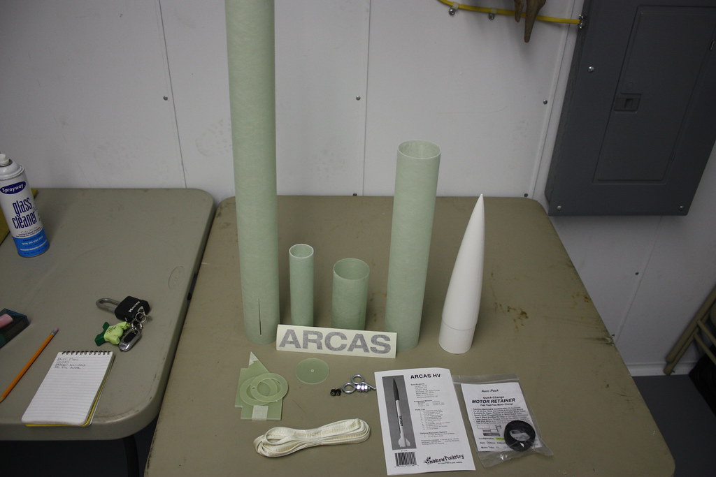
I have spent tons of time trolling build threads, and finally decided to try one for myself. I will be building a MC ARCAS, planning on DD using a Stratologger for deployment control and BRB 900 for tracking. I decided to start with the e-bay.

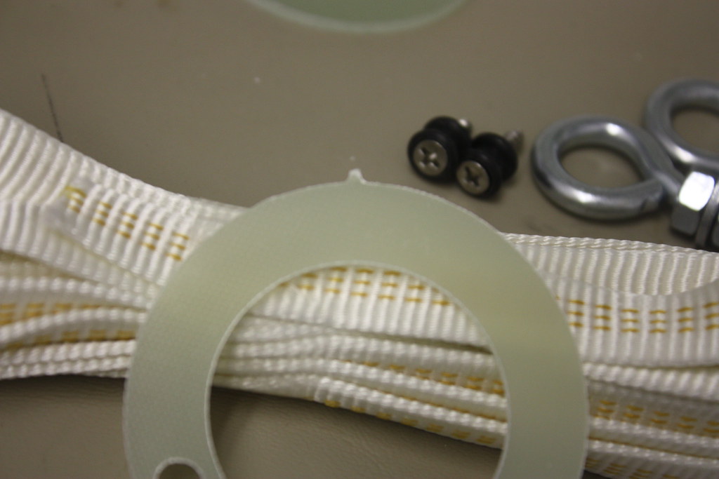
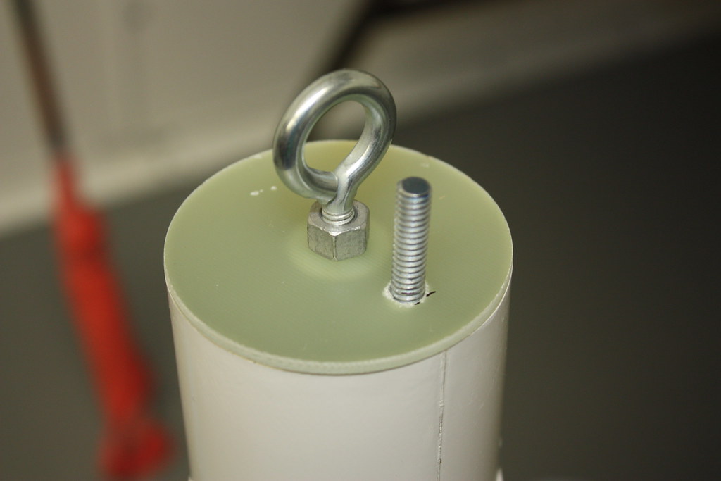
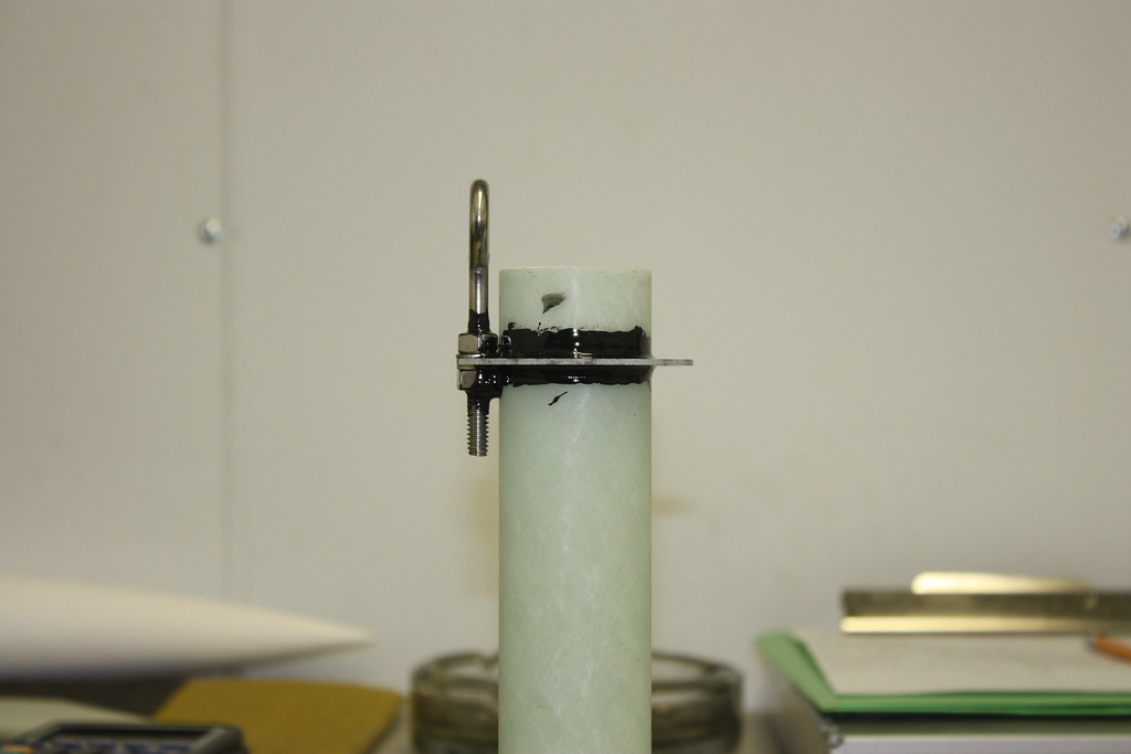
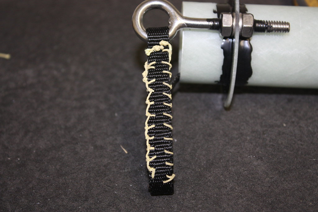
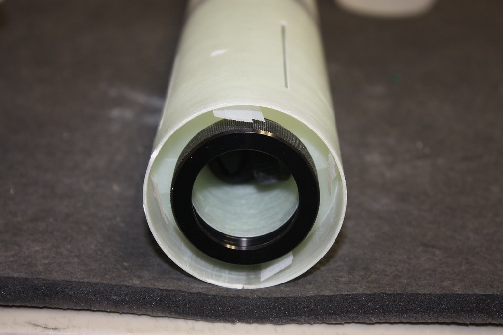
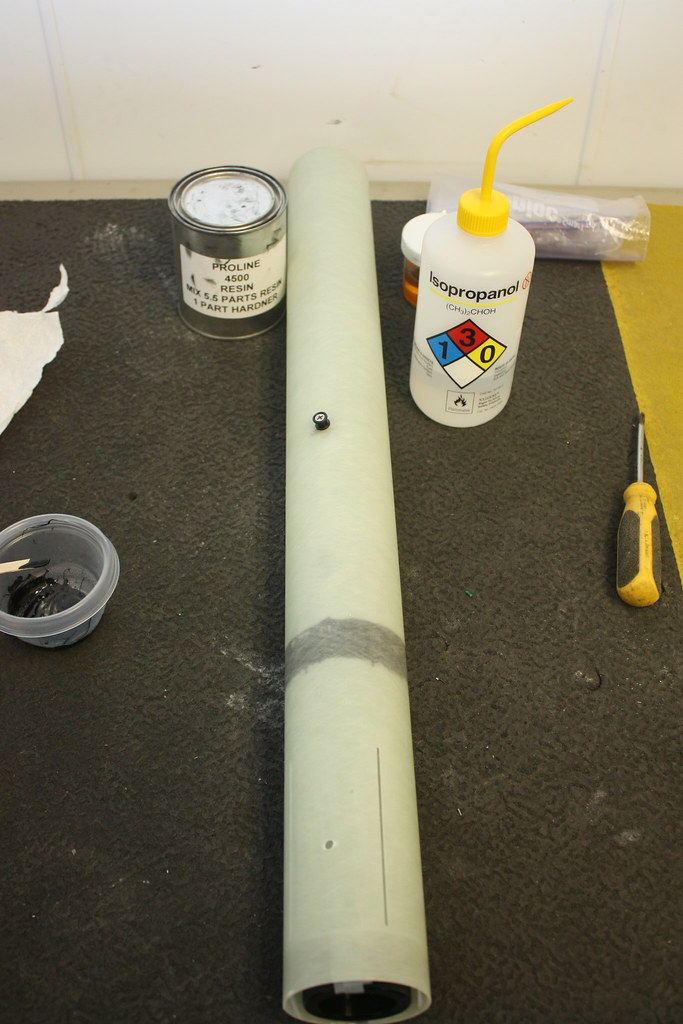
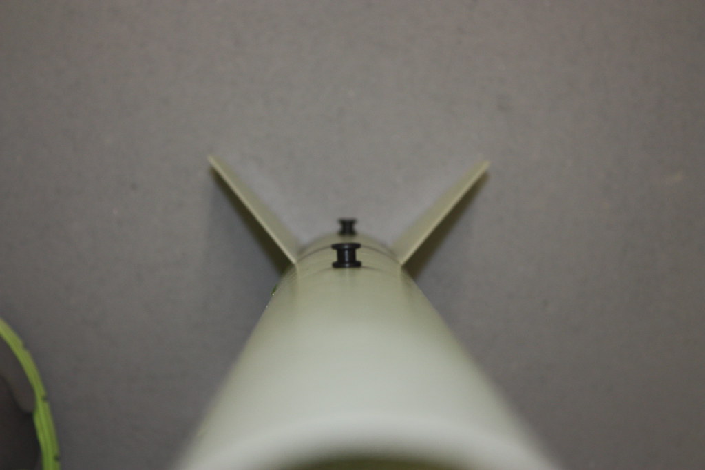
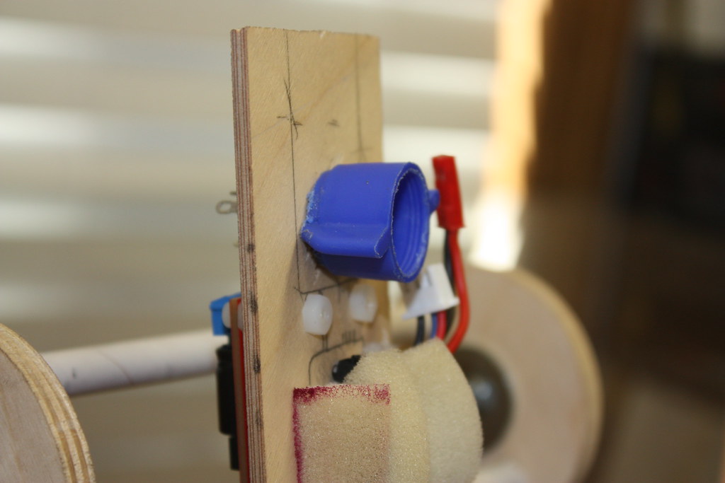
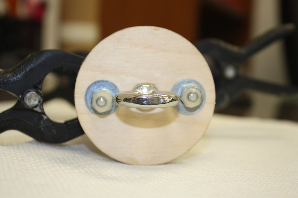
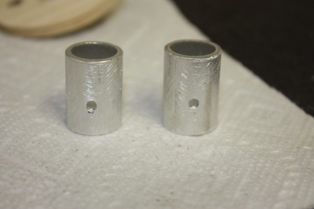
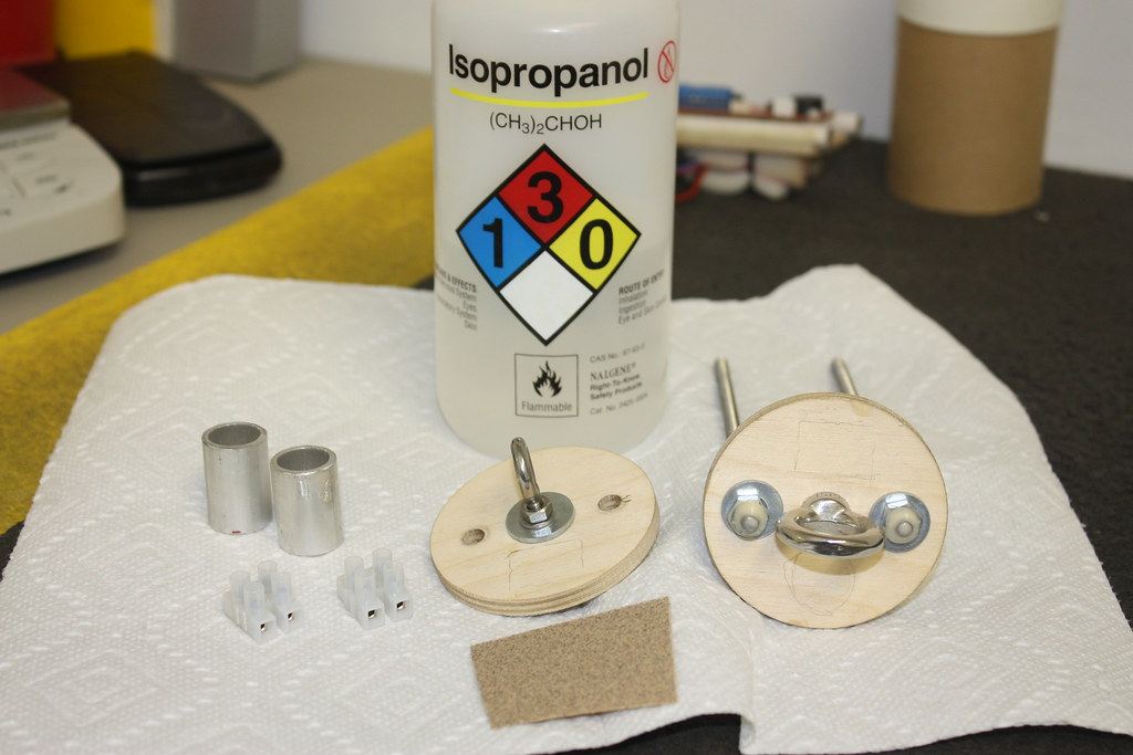
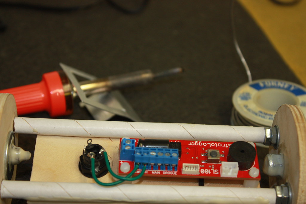
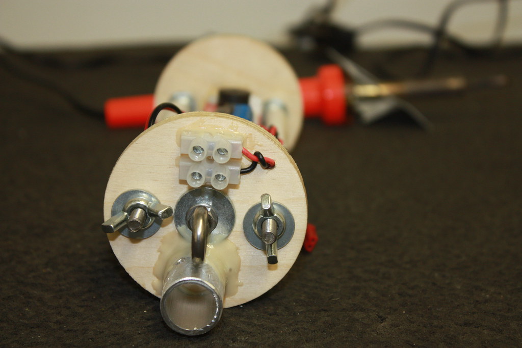
I am using a LOC e-bay, I first cut the mounting tubes and sled. I have also fitted the e-bay with welded eye bolts purchased from Aeropack, Nylock nuts, and will be using the rotary switch pictured.
12056883143_3a78a944d9_b.jpg


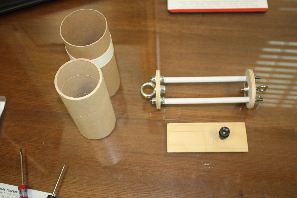
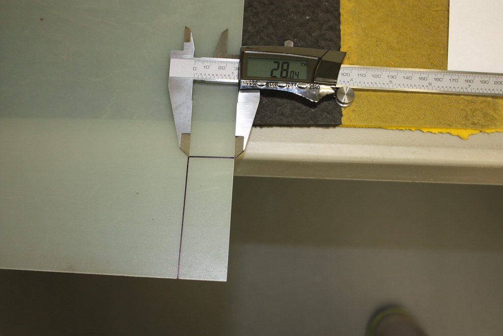
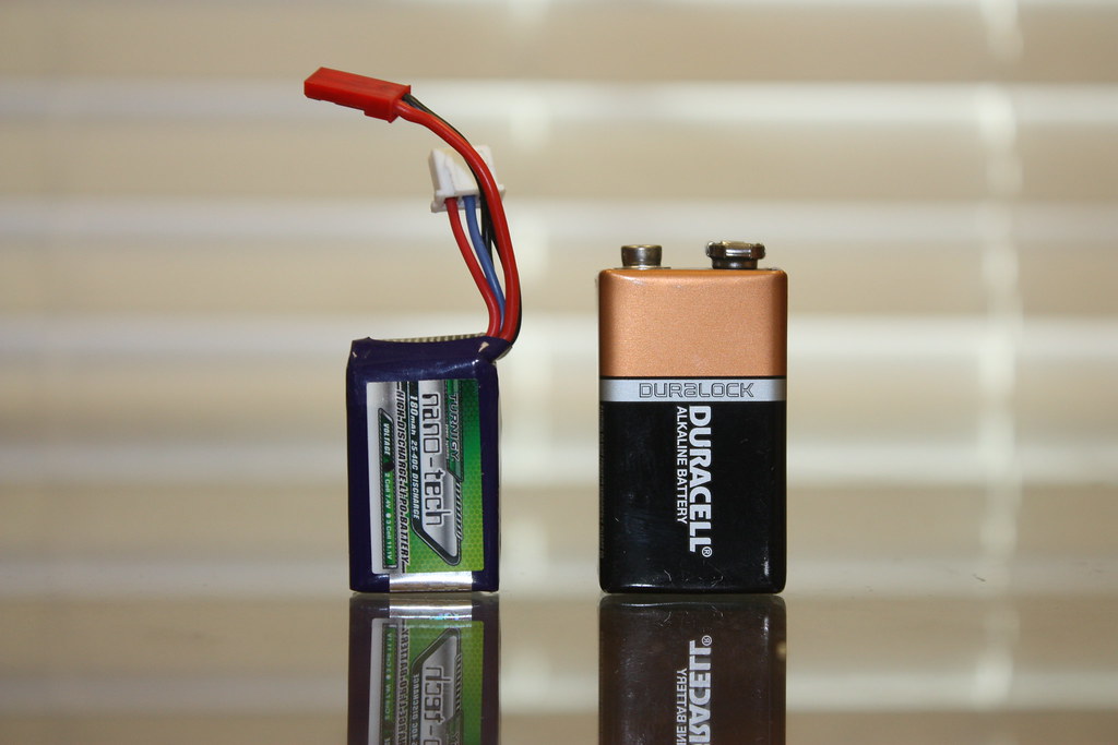
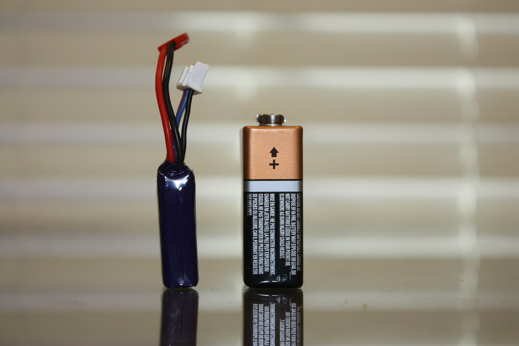
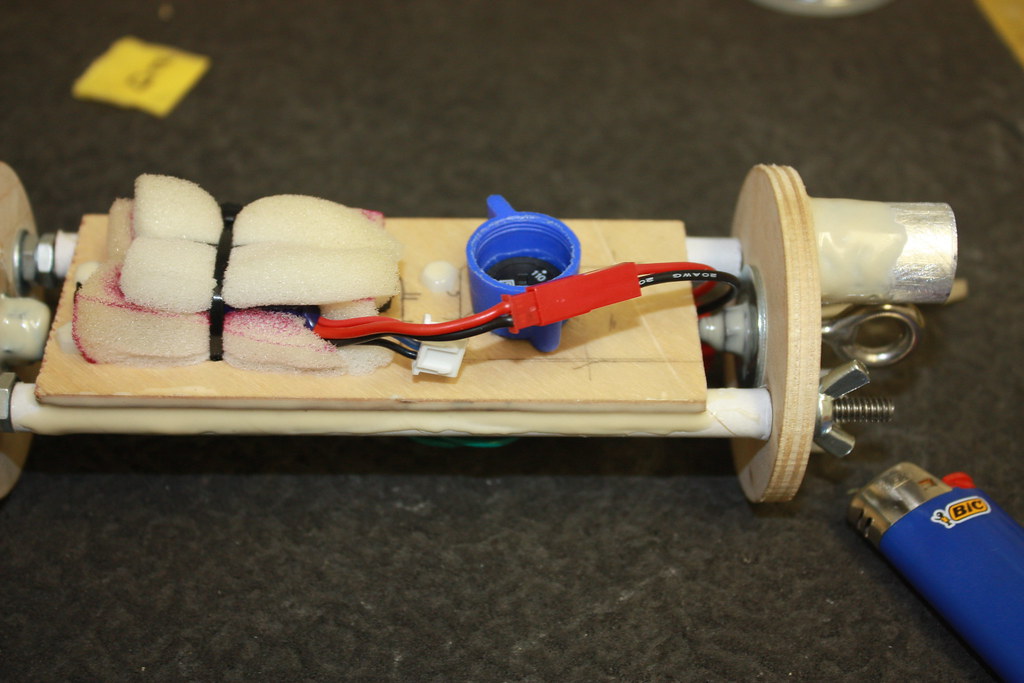
2.56" does not leave much room inside an e-bay, so after reading several threads concerning LiPo batteries, I am trying one for my first time.
12056525645_a3d350d6b0_b.jpg

12056559585_804997ca10_b.jpg


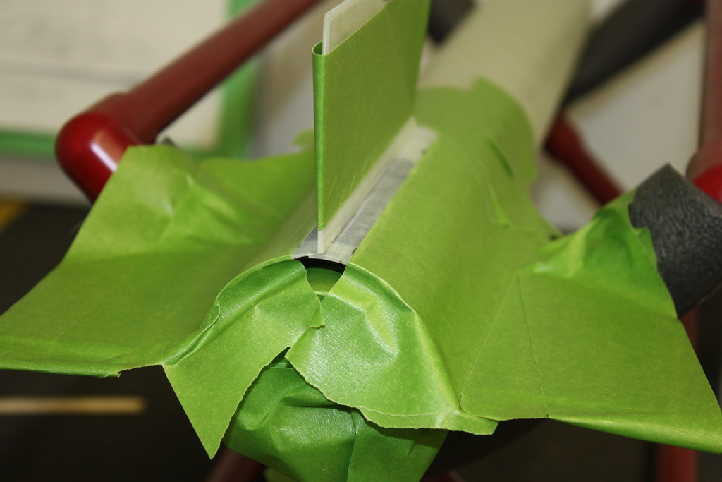
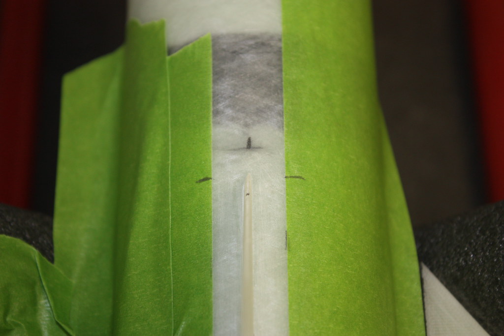
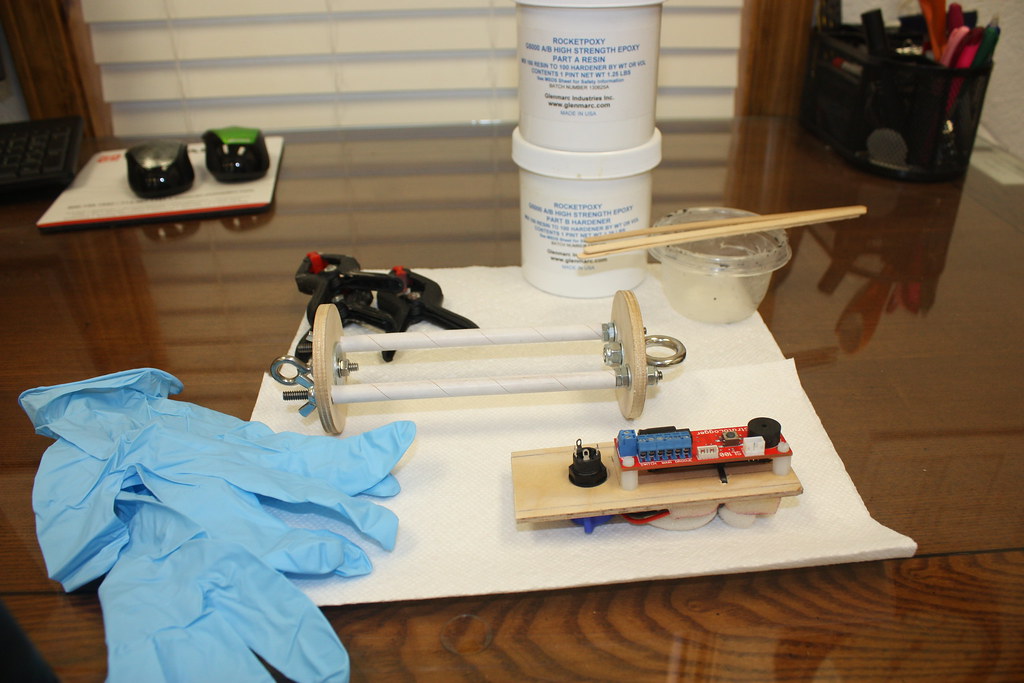
I started by measuring, drilling, and tapping the 4-40 mounts for the Stratologger, then drilled and mounted the switch.
12056911723_d8720aa09a_b.jpg


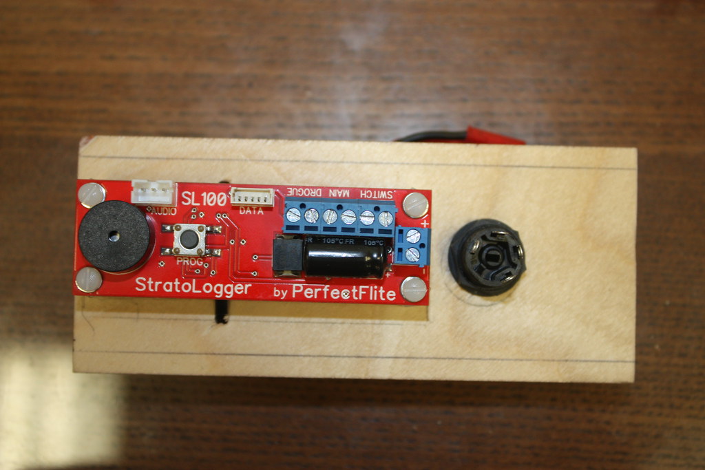
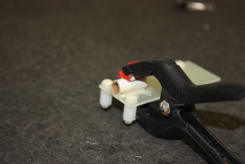
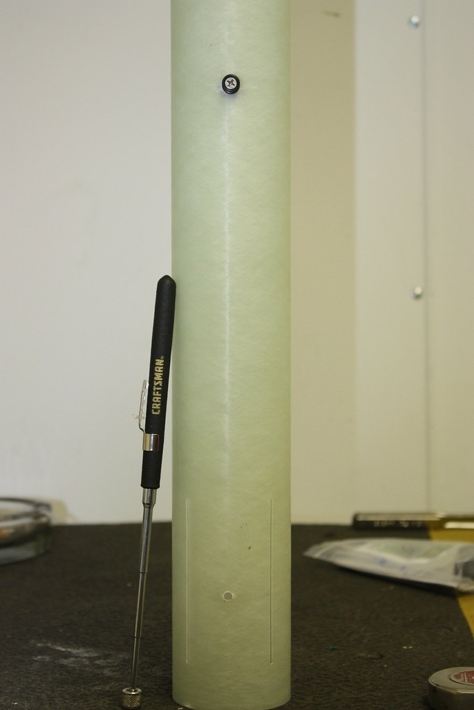
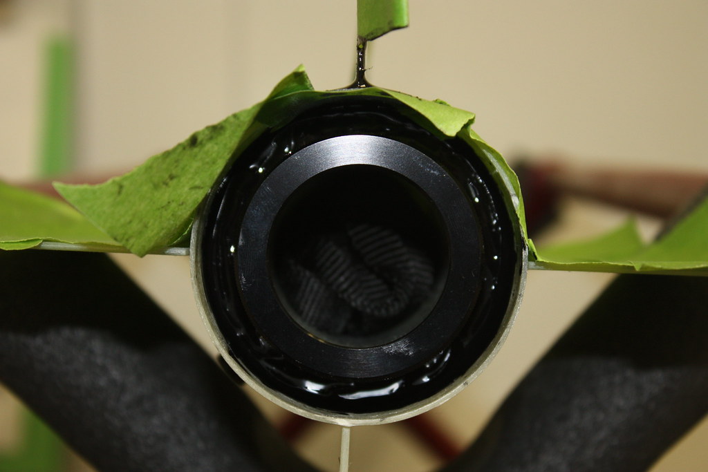
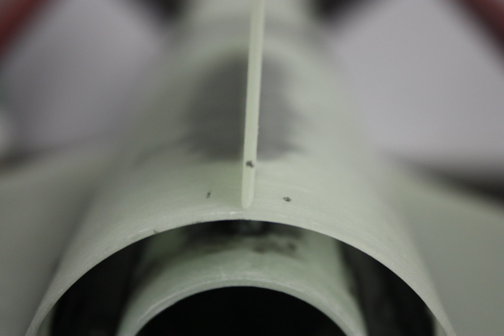
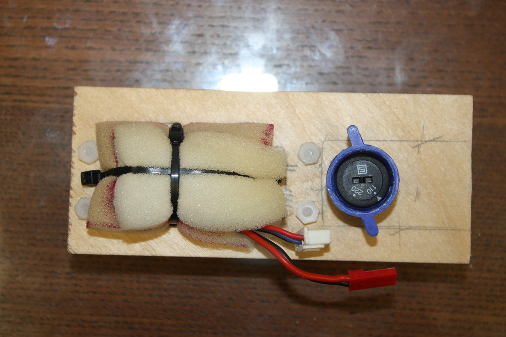
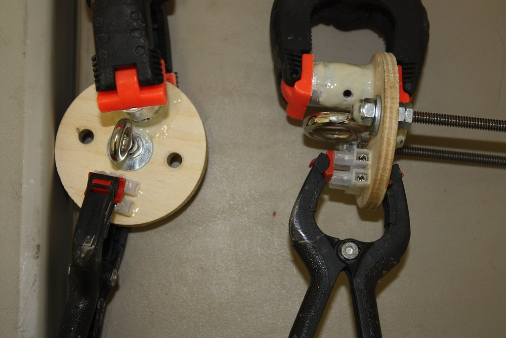
I'm using a technique found right here on TRF to help guide the screwdriver to the rotary switch by using half a wire nut.
12057109274_5b3518425a_b.jpg


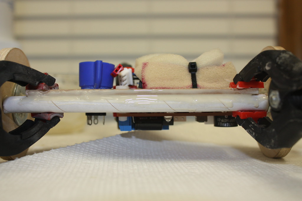
I made a cutout in foam to fit the LiPo, and then cut a cover out of the same foam. I drilled four holes and zip-tied directly to the sled.
12057535116_ae3f4e11db_b.jpg


Now to epoxy the sled and any loose ends.
12057636576_8c1642ed0c_b.jpg

12056493675_64c41ee399_b.jpg

12056800454_5b44189b70_b.jpg


Next is the e-bay bulkheads.
 
I cut my own ejection canisters out of Aluminum.
12099936275_5a000990b1_b.jpg


Next was to clean and sand everything.
12100266093_2f94179cbc_b.jpg

Finally epoxy then the clamps.
12100329454_369cbac6b9_b.jpg


After everything cured, I started by soldering wire to the switch then attaching to the altimeter.
12135647014_bb8260253a_b.jpg

Now to connect the battery. I purchased the JST-Open wire connector when I purchased the battery. Everything came from hobbyking directly from links in a TRF thread that I will try to link here later. (2 batteries,Male JST Connectors, Female JST Connectors, and multi-functional automatic charger through the USA warehouse for ~$70)
12135857746_af4dbc5d4f_b.jpg

Next was to run the wires through the bulkhead for both the drogue and the main. I use lots of extra wire to ensure easy placement/removal in the field.
12135841076_0c1ce3605c_b.jpg


Finally before sealing the bulkheads, a continuity check using a handy dandy christmas bulb and the PerfectFlite dongle - software interface.
12135548524_ae4b759250_b.jpg

While I had everything including the laptop connected I decide to test my new LiPo-Stratologger combination with lighters purchased right here on TRF from CJ (@FANTASTIC PRICES!!!) Another link I will work on later.
12135988296_f7e35b21b9_b.jpg


BOOOYAAAAAA!!!!! Thanks CJ, AWESOME LIGHTER!!!
12135312295_de19278130_b.jpg


After successful testing I went ahead and sealed the wires running through both bulkheads inside and out.
12135943206_8477f0d262_b.jpg


Next up is to figure out how to mount my BRB 900 in the NC.
 
Ok, unpackaged the kit and took the obligatory stock (except the Aeropack retainer)parts picture for this build.

The parts were pretty well covered in FG dust.
12143262843_ceee8490ef_b.jpg


I do not want to come off as whiney, but I identified a few things that will need some work.
12143001525_8c18f2b303_b.jpg

12142988645_a62aa497f2_b.jpg


My origional intention was to center the BRB 900 on 1/4" all-thread, but during test fitting found the battery connection did not have enough clearance in this configuration. This lead me to offset the BRB and center my recovery attachment.

I started by cutting a FG sled as small as possible for the BRB
12143378204_f8dd502fb7_b.jpg


I drilled and tapped the mount, attached the BRB and found an appropriate mounting tube.
12143607156_3c7c23c7df_b.jpg


Used a spare 2.56" plywood coupler bulkhead to mount the offset all-thread, and secured with a 1/4" Nylock nut.
12142936135_8672029a50_b.jpg


I always test fit a lot before mixing up any epoxy. This shows the coupler bulkhead/all-thread seated in the NC.
12143708546_c94de7fd1a_b.jpg


I usually avoid eye bolts that are not forged or welded, but one of the included eye bolts was the only one I had with a short enough shank to ensure no interference with the BRB. I attached the eyebolt to the center of a 2.56" AF bulkhead with a 1/4" Nylock.
12143438804_7aeeeb39ff_b.jpg


Test fitted the entire assembly, and am pleased with the result. The 0.25" All-thread is stiff enough to offer an adequate seal when secured with a Nylock, and is rigid enough not to allow any bulkhead seperation while nominal stress is applied to the centered recovery attachment.
12143025625_2767118096_b.jpg


I mixed up some rocketpoxy and covered the ends of the permanent Nylock attachments, and epoxied the plywood bulkhead in place. I slid the NC/Bulkhead into a section of the AF so the epoxy would cure holding the bulkhead in the appropriate position.

Considering the wind is gusting ~50mph at the moment and forcasted to get worse (gotta love the TX panhandle), I plan to spend the next two days in the workshop so expect plenty of build updates soon!
 
I finished the NC a few days ago, and wanted to show how it turned out after the rocketpoxy cured.

As mentioned earlier, I used the AF to make sure the NC bulkhead cured in the right place.
12237837735_a55bb9c7dd_b.jpg

12238422586_18875e6869_b.jpg


Used a leftover piece of the tubing cut from the LOC Ebay set for the BRB900 sled. I sealed the ends of the tube with CA after the epoxy cured
12238048713_ebb98801b3_b.jpg


Probably a little overkill on the epoxy, but is definitely a strong bond.
12238241824_f4eeb9db95_b.jpg


The tracker is nice and secure.
12237813485_71d84787cf_b.jpg


The NC bulkhead is secured using a 0.25" Nylock nut, it would be a pain without a deep socket, but I am confident in will not vibrate loose.
12238215084_2b301494eb_b.jpg


I realize it could probably done lighter, and still be "strong enough"; I want to feel "warm and fuzzy" when the countdown begins. Overall at ~270 grams, not bad.
12237970863_d5bba5bf20_b.jpg


Tried out the newest edition to my tool collection, although this is a little small of an application for this sander, I LOVE IT!:D I will be looking for excuses to use this all weekend :fly:
12237957673_35d9269185_b.jpg
 
Last edited:
On with the build!!!:horse:

I use a homeaid - plumb-bob?:confused2: NO IDEA IF THAT IS THE TERM! It is just a forged eyebolt tied to a string-line, uses gravity to draw a straight line. Forgot to get a picture of this exremely high tech tool. :blush:

I marked and drilled both holes for Aeropack 1010 rail buttons. Used a magnet fish the T-Nut into place.
12238566216_b330800e7b_b.jpg


Attached an Aeropack 0.25" welded eyebolt through the pre-drilled hole in the forward CR. The nuts BARELY fit without causing clearance issues. As typical with most of my builds, I use Proline 4500 for all bonding of the MMT and fins. I spread a little epoxy on the nuts/threads of the eyebolt to make sure it can't come loose.
12238553896_e4b39570c1_b.jpg


Now please don't laugh too hard at my technique, but I prefer to hand sew my own recovery attachments using #100 Kevlar cord. I am using ~9' of PML recovery strap for the drogue harness and the included harness for the main. I currently plan to fly drogueless.
12238332576_f3de7e0f66_b.jpg

12238286816_f7d008d524_b.jpg


Started by sewing in a LOC swivel.
12238368534_ac25a81382_b.jpg


I always give my finished product a good helping of yellow glue to secure the knots, and keep any of the ends from fraying.
12238350664_9db8b55f05_b.jpg


I sewed a permanent loop around the rear drogue recovery attachment eyebolt.
1/2 Sewn
12238496446_576ac8fe5f_b.jpg

Fully Sewn before final glue coating. Once the glue set I pushed the drogue harness into the motor tube to keep it epoxy free during the rest of the build.
12238480046_dffaec55c9_b.jpg


I considered using the WM-FILLET INJECTION TECHNIQUE, but have never done this. The fin tabs on this kit are fairly close to the rear, and do not extend the full length of the fin so I feel confident I will be able to apply the internal fillets with my standard popsicle stick method. I cleaned everything with alcohol, and then sanded everything that would be epoxied on the inside of the AF, including the MMT. I used tape to make tabs to remove the rear CR after the epoxy dried to allow access to the internal fillet area. I dry-fit the Aeropack motor retainer to get the placement I wanted, leaving ~0.25" of the retainer past the rear most of the AF. I almost put the retainer flush with the rear AF, but was afraid I wouldn't be able to remove it without a fight later.
12238467856_c6743bc5ce_b.jpg

Not hard to see where the epoxy for the forward CR is at. I used a very small amount of leftover epoxy on the threads of the forward launch lug screw to keep it from backing out of the T-Nut.
12237879895_23228ced02_b.jpg
 
The next step was to bevel the fins. I used 100 grit sandpaper to lightly bevel the leading and trailing fin edges.

This shows a before and after, I do not know how much this matters performance wise, but I like the finished look much better.
12250169956_97248b8536_b.jpg


Next was to tack the first fin. I keep meaning to build a fin jig, but keep using the estes model shown. I even used this for my L2 on a 4"Formula 98.
12250106374_4dc4515dda_b.jpg

12249853753_0442cc9727_b.jpg


About 4 hours after tacking, the Proline was set up enough to tape the outer AF around the first fin, and apply the internal fillets. After finishing the internal fillets, I tacked the second fin.
12250083434_306c897972_b.jpg

12249658485_7fbf55678a_b.jpg


One more cup of coffee then it's back to the shop for more fin!!! I mean fun!!!
 
Love your work Cory. I just wanted to show you a method I came up with when installing electronics in the NC.
I wanted to keep from drilling so many holes in the NC bulkhead. Instead of drilling another hole for an eye bolt,
I used an angle bracket as an anchor point. Keep up the great work!
GEDC0059.jpg
 
I hope everyone continues to enjoy the progress. This is my first build thread; having subscribers somehow adds pressure. :duck:

Thanks for the advice Bill, I'll definitely keep the angle bracket in mind on future builds. :handshake:
 
This gets a little redundant at this point, but for posterity on to fin 3. First was internal fillet 2, then tacking fin 3.

12281103056_637abbb7f5_b.jpg


While fin 3's Proline tack was drying, I went back to the ebay/coupler. I spent a lot of time considering where to put the switch band since my switch is not centered, but about 1/3 of the way down from the top. I first considered abadoning the switch band to maintain scale, but decided against. I also considered locating the switch band directly over the switch ~1/3 of the way from the top, but this would make the drogue seperation point really long, and I was unsure if the forward AF would stay rigid under boost with only ~1-2" of coupler. In the end I decided to mount the switch band in the center of the coupler, and I plan to drill the switch access hole directly over the switch above the switch band and align the atmospheric sampling ports with the access hole. I need an 11/32" hole for switch access, and this is such a small ebay 1x11/32" hole may adequate to use as a single static port. I think I oversized the ports on my L2 build, which caused fairly noisy readings during the flight on both RRC3 and Stratologger used. I do not want to repeat this mistake,but don't want to under-do it either. Advice welcomed!
Light pencil markings along the center of the coupler for reference.
12281084686_974123467a_b.jpg


With the LOC stiffy tube and plywood ebay bulkheads in place, it was easy to see through the fiberglass coupler and mark where the bulkheads and stiffy tube met.
12281074666_b04e0f4006_b.jpg


Got everything cleaned and sanded, then remarked the lines. :facepalm:
12281074666_b04e0f4006_b.jpg


This application called for the 5-minute epoxy.
12280938864_bcffd97b00_b.jpg


Once I got everything on line, I immediately wiped ALL excess epoxy to ensure both the AF/Switch band and plywood/stiffy junctions would stay uniform.
12280646233_332041e453_b.jpg


I would rather have a bunch of unused noted weights than make any more assumptions than absolutely necessary in Rocksim.
12280914664_4762d1b3d8_b.jpg


Next was some more not so fancy, but functional recovery harness sewing. I was initially nervous how soft the Madcow material was, granted it was easy sewing. My fears evaporated once I realized it soaked up yellow glue like an angry sponge. The pictures are pre-glue, but I am definitely pleased with the final product.
12280448755_af825cf9b6_b.jpg

12280599995_069df61b37_b.jpg
 
Got internal fillet 3 and fin 4 tacked, finally starting to look like a rocket! :grin:

12280610183_0884a2787b_b.jpg

12280901944_9f9bc592ea_b.jpg


As soon as the tack set, finished up the last internal fillet. Not a huge gap between the MMT and AF, but overall the popsicle stick handled the internal fillets pretty well. Proline is the messiest epoxy I have used to date, but in the end I am extremely confident in the bond.
12281009224_d8c821d637_b.jpg


After application of the final internal fillet, while the epoxy was still usable, I installed the rear rail guide. I'm hoping my eyes are just crooked, but I am ~80% sure the rail guides are out of alignment. I have a 1010 rail to use, HOPEFULLY it doesn't bind, or it's out with the forward guide, epoxy putty the hole, redrill, and replace. :bang:
I usually use the plumb-bob hanging from a rear centered guide to align the forward guide. This time I decided to use my "handy-dandy" plumb-bob to mark both holes, and well I won't do that again. :mad::bangpan: I would love to know how other people align rail guides, aside from using a door-frame (not useful for larger projects).
12280717783_1ff6d630e6_b.jpg


Overall a good weekend in the rocketshop, I am hoping to make the maiden flight, primer only, March 1st with POTROCShttps://www.potrocs.org/, leaning towards the CTI I470 for a first flight, and if all goes well a CTI J354. Rocksim is simming ~4700' with the I, and ~7000' with the J!:headbang:
 
After finishing all the internal fillets, the next step was to epoxy the rear CR and Aeropack retainer using Proline 4500. First thing is a thorough clean and sand, in some cases re-sand, the areas to be bonded. I have been using 100 grit paper, but I am considering using 60-80 on future FG builds.

12373992734_0e7fe34c3f_b.jpg


Using a caliper, I measured .35" from the fin base over the AF, .30" from the AF/Fin Joint over the fin, 0.25" past the front of the fin then centered with the fin to form a point. Lightly marking the measurements in pencil to guide the tape placement.
12373724793_9a781e13eb_b.jpg

12373470585_e8361b2d0a_b.jpg

12530753283_01a6d5920a_b.jpg

12530740983_5c67a869e6_b.jpg


Using a craft stick, I intentionally over apply the epoxy.
12530587755_b010943daa_b.jpg


I have a question to interject, and I hope I can get an answer inside this thread, but if not I may post it as a thread of its own. I am unsure of the differences between using Isopropanol (IPA) and 2-propanol (2-PA) for epoxy solvent in HPR. I have a hard time sourcing high purity IPA at reasonable prices, but have no problem ordering 99%+purity 2-PA on Amazon. I have been using 2-PA in the place of IPA and it SEEMS to act the same, but is it okay to substitute?

Anyway using a gloved fingertip wet with 2-PA, I "pull" the fillets. This is my first try with tipped fillets (usually left square) and I got a little thin a few times at the tip.
12373426945_f4c2dca288_b.jpg

12373673263_9580c33114_b.jpg


The tape is ready to be pulled 1-1.5 hours after application, depending on speed of application and room temperature. I use small GLADWARE for mixing batches of epoxy. They are flexible enough, if the epoxy is spread thin before curing, it can somewhat easily be broken out and the container re-used several times. I do not mix epoxy types, and designate the cups for 1 type epoxy only. Using a craft stick I check the batch used for mixing the epoxy and hardener every 5 minutes starting about an hour after mixing. As soon as the craft stick begins trying to tack to a relatively hard surface in the cup, I pull the tape (before the "tack" point the Proline is easily manipulated and if you pull the tape at this point it is like pulling pizza apart, and usually leaves behind several spider web thick strands laying perpendicular to the fillet).

12373900374_b65c81e0bd_b.jpg

12373913264_e1cc0d4a7a_b.jpg


Over the course of a few days I finished all the external fillets. Plus, was able to test the rail-button alignment using a 1010 rail, and there is more than enough slop in the OD of the buttons and the ID of the rail it fits NO PROBLEM.:roll:

I plan on drilling the forward half of the e-bay for removable plastic rivets & drilling and tapping the NC and rear half of the e-bay for shear pins. I plan to use 2-2x56 Nylon screws for both points. I realize the shear pins in the rear are not necessary. Definitely plan to do plenty of ground testing for separation, but I am not sure if how to test/simulate drag separation of the rear half at burn out so will go with pins.
 
Love this rocket. You need to challenge it to the max. It is a brute and it can take it. This is my FG Arcas launching on a CTI J530 to 8.696'. I put my BRB tracker in the nose cone and used an Adept 22 for the altimeter. Since the delay on the J530 was too short, I took out the motor ejection charge and instead used a Perfect Ftite MT-4 timer as a backup ejection system to at least separate the rocket so it would not come in ballistic.

Launch 062213.jpg
 
I love my Madcow HV Arcas....
It's a fantastic flying rocket.......
It was a great build.....
I did my first mile high flight on this Arcas.........

Teddy

5-18-13 024.jpg5-18-13 025.jpg5-18-13 032.jpg5-18-13 040.jpg
 
Using a craft stick, I intentionally over apply the epoxy.
12530587755_b010943daa_b.jpg


Anyway using a gloved fingertip wet with 2-PA, I "pull" the fillets. This is my first try with tipped fillets (usually left square) and I got a little thin a few times at the tip.
12373426945_f4c2dca288_b.jpg


The tape is ready to be pulled 1-1.5 hours after application, depending on speed of application and room temperature. I use small GLADWARE for mixing batches of epoxy. They are flexible enough, if the epoxy is spread thin before curing, it can somewhat easily be broken out and the container re-used several times. I do not mix epoxy types, and designate the cups for 1 type epoxy only. Using a craft stick I check the batch used for mixing the epoxy and hardener every 5 minutes starting about an hour after mixing. As soon as the craft stick begins trying to tack to a relatively hard surface in the cup, I pull the tape (before the "tack" point the Proline is easily manipulated and if you pull the tape at this point it is like pulling pizza apart, and usually leaves behind several spider web thick strands laying perpendicular to the fillet).

12373900374_b65c81e0bd_b.jpg

Just a quick question? Why do you do both sides of the same fin at once. I've always done the left side of one fin and the right side of the other, like this post. That way the fins are angle upward and the fin/BT form a valley and I get a fillet that is more evenly distributed. It seems your fillet are wider/thicker on the BT then the fins because of doing a single fin at once. Is there a specific reason for that?
 
Thanks for all the feedback. I appreciate all the positive comments and welcome constructive criticism.:pc:

You need to challenge it to the max. It is a brute and it can take it. Since the delay on the J530 was too short, I took out the motor ejection charge and instead used a Perfect Ftite MT-4 timer as a backup ejection system to at least separate the rocket so it would not come in ballistic.View attachment 162331
Considering it will handle even the longest 38mm 6GXL, I definitely plan to push it. I am having the same problem with the motor ejections being shorter than simulated coasting flight. I don’t mind pulling the motor charge, but I would like some level of redundancy for the same reason you state. Where did you locate the timer? I am mostly out of room in the e-bay.
This build makes be REALLY want one. Alex
I know you are allergic to motor mounts, but a 54mm would be REALLY close to MD.
Just a quick question? Why do you do both sides of the same fin at once. I've always done the left side of one fin and the right side of the other, like this post. That way the fins are angle upward and the fin/BT form a valley and I get a fillet that is more evenly distributed. It seems your fillet are wider/thicker on the BT then the fins because of doing a single fin at once. Is there a specific reason for that?
Good observation, I do it this way because I have always done it this way, not because it is better. The fillets are undoubtedly wider and thicker at the base (.35@base -.30@fin). I agree the way you suggest would end in a more uniform fillet thickness, but how would you go about handling the area forward and rear of the fin. In this method are the forward and rear areas done in halves also, or as a third part after both sides are cured? I would definitely like to give it a shot, just having a hard time understanding how to blend the two sides past the fin joint.
This also leads me to another question, I agree this is a heavy-duty kit, but have zero personal experience with transonic or supersonic flights. Is the method of fin attachment utilized in this build suitable for Mach 1 flights, or should it only be flown subsonic without re-enforcement?
What's better than a Mad Cow HV Arcas? Perhaps a 2-stager?View attachment 162377

:eyepop: I don't have any experience with HPR staging, but seems like there is plenty of room stock behind the rear CR for an interstage coupler. No doubt with the right skills and experience, this could be made into a GREAT two-stager. If you build one DEFINITELY need a build thread.:D
 
Don't have a photo of my AV bay, but the battery and the timer fit on one side of the sled, and the altimeter fit on the other. Both altimeter and timer ran off the 9V (wired in parallel so that if one died the other was still there. An extra set of terminal posts were attached to the rear bulkhead of the AV Bay and an e-match and charge was attached to that terminal. Relatively simple. The MT-4 is about the size of a quarter, so it doesn't take much room.

I do have photos of how I attached my fins. I did not glue in motor tube until after the fins were glued and glassed to the airframe. that way I had time to attach the fins with strips of glass cloth. The forward CR was glued into place and positioned by sliding in the MT and dryfitting the aft CR. Then the aft CR was removed. I used an Estes fin alignment guide, slid down over the motor tube (I have a 24mm-29mm adapter and a 29mm-38mm adapter so I can use this tool for up to 4" airframes. I then just glued the fins in at the airframe. After that I slid out the MM Tube and that left me plenty of room to glass in the fins. After those were done, I used liberal amounts of epoxy to glue in the MM tube and rear CR. I knew I was going to challenge the rocket, and I wanted to make sure the fins were going to stay attached.

Gluing on the fins.jpg
Fins Installed.jpg
Interior Fiberglass.jpg
Completed Fin Can.jpg
 
This also leads me to another question, I agree this is a heavy-duty kit, but have zero personal experience with transonic or supersonic flights. Is the method of fin attachment utilized in this build suitable for Mach 1 flights, or should it only be flown subsonic without re-enforcement?

I tend to like a little wider and thicker fillets internal and external. I think that gives it more strength. As for how you did yours, I would say the fins should hold up past Mach. They are not the best shape for Mach speeds, the clipped delta is the best, but you shouldn't have any worries. The fin attachment isn't really what you have to worry about, it's fin flutter. Solid fillets help keep the flutter down, but if the fins flutter too much, the fin or BT can fail before the joints do.
 
Last edited:
I've flown mine past mach 4 times. Once the main got stuck in the airframe and did not deploy. Another time the shock cord holding the lower airframe to the av bay broke. Fins were fine both times.
 
Solid fillets help keep the flutter down, but if the fins flutter too much, the fin or BT can fail before the joints do.
I've never seen an epoxy joint exceed the strength of a composite material. Every fin involved shed I've ever seen was the entire fin shearing off the body tube. You would have to use massive fillets on insanely thin material to reverse that.
Using bigger fillets will have little effect on flutter. Flutter is completely dependent on stiffness of fin material and and shear strength is dependent on attachment techniques.
Stiffer fins will flutter less and put less stress on the fillets. Flimsier fins will put more. I generally think of it as: the stiffer the fin material, the less you need to reinforce it.

In this case, I agree with you that cory wont be able to shred his rocket. TTW fins are extremely durable.

Alex
 
....They are not the best shape for Mach speeds, the clipped delta is the best, but you shouldn't have any worries... .

I could be mistaken, but I think these ARCAS HV fins are clipped delta. Used G. Harry & Bill Stine's 7th Edition HANDBOOK OF MODEL ROCKETRY, p.154 for verification.:confused:
12249622165_70439ecd3e_b.jpg


Made some good progress over the last six days, look for a thread update soon!
 
The next step was to drill and tap 2-2x56 shear pins for both the NC and rear separation point. While I had the drill and paper template, I went ahead and drilled holes for the removable plastic rivets.
12758821683_8a6daf37ef_b.jpg


I found a 1/8" diameter screwdriver that worked fine to operate the rotary switch, so I ended up settling with 3x1/8" holes above the switch band pressure compensation and switch access. The inside of the stiffy coupler looked pretty rough after all the drilling, so I took a little time to trim the inside "fuzzies" and then sealed all the edges with thin CA.

Went ahead and got a dry weight (1663.9 grams) with the 54" PML chute I received a few weeks ago, and manually measured the CG to see how my rocksim file compared.
12759096044_30f3bf05b7_b.jpg


I wired the e-bay terminals together and tested ejection charges one side at a time. Settled on 0.5g for the main, and 0.6g for the drogue (all using FFFFg).
12759279144_75a1e42ef1_b.jpg

12758799955_95932006c2_b.jpg


Now for my least favorite part, finishing. I started by dry sanding everything with 220 grit, wiping with a tack cloth, and spraying 5 light coats of KRYLON White primer 1 minute between coats. I repeated the same process 24 hours later after filling a few minor imperfections (~1.75 cans of paint total).
12759220814_e3b38145bb_b.jpg

12758736455_a2215c233d_b.jpg


At this point it is not quite "perfect in primer", but I don't want to waste too much weight on paint so I decided to move on. I wet sanded the last coat of primer with 400 grit before spraying 4 LIGHT coats of KRYLON Gloss White.

I stopped there (sorry no picture of the gloss white coat) hoping for a maiden launch today before finishing the scale paint scheme. Unfortunately, the weather did not cooperate and the launch was cancelled. I am so happy with the progress though, I plan to finish the paint and apply the decal (as the weather permits) before the maiden flight. Weight minus AP at this point is 3.785 pounds.
 
Whats even the point of doing fillets if you dont do the left side and right at the same time creating a valley for the epoxy to get evenly distributed? Also, why do fillets if you dont sand them down smooth so you can see them once you paint? One more thing Proline epoxy is expensive, if you dont go the extra mile and make them look perfect whats the point in spending that much on it? I have used 5 minute loctite epoxy from lowes on many fiberglass birds and sanded and made them look perfect. The bottom line is if your gonna spend the cash, make it the most smooth aerodynamic rocket you can make.
 
After application of the final internal fillet, while the epoxy was still usable, I installed the rear rail guide. I'm hoping my eyes are just crooked, but I am ~80% sure the rail guides are out of alignment. I have a 1010 rail to use, HOPEFULLY it doesn't bind, or it's out with the forward guide, epoxy putty the hole, redrill, and replace. :bang:
I usually use the plumb-bob hanging from a rear centered guide to align the forward guide. This time I decided to use my "handy-dandy" plumb-bob to mark both holes, and well I won't do that again. :mad::bangpan: I would love to know how other people align rail guides, aside from using a door-frame (not useful for larger projects).
I use a couple different pieces of angle. One is 2"x2" and the other is 4"x4". They cover everything up to a 7.5" airframe]


Sent from my iPhone using Rocketry Forum
 
Whats even the point of doing fillets if you dont do the left side and right at the same time creating a valley for the epoxy to get evenly distributed? Also, why do fillets if you dont sand them down smooth so you can see them once you paint? One more thing Proline epoxy is expensive, if you dont go the extra mile and make them look perfect whats the point in spending that much on it? I have used 5 minute loctite epoxy from lowes on many fiberglass birds and sanded and made them look perfect. The bottom line is if your gonna spend the cash, make it the most smooth aerodynamic rocket you can make.

First, please take into account two things, my inexperience (this is my 2nd FG build), and my strong dislike of sanding. Personally, my goal when painting is to achieve a really nice look at 10+ feet.

For me, the external fillets are mostly to make the fin more rigid to negate fin flutter as much as possible. I could certainly be mistaken, but wouldn't the 2x10¹⁰ rail buttons serve to increase the Cd more than the 4x~1/32" tall external fillets?

I think you are a little unfair to Proline. I use it for fin/MMT bonding, and fillets because it can handle ~100°F higher temperatures than the best LOCTITE. Considering my intention to fly longburn motors, and hopefully past Mach 1, this seems important. Not the cheapest epoxy, but for Wildman Club members (I am) 1 pint of Proline is $37.05. That is cheaper than, for Wildman Club members, 1 CTI Pro38 3 Grain I345 RELOAD ONLY which costs $37.76. I have built a 4" Formula 98 plus this ARCAS HV, and have used less than half of my pint.

There are undoubtedly MANY ways to build this rocket to fly higher and faster including a tail cone to reduce base drag, use a tower and do away with rail guides, use a smaller lighter parachute, shorten the rocket to a minimum CG/CP separation value, use permanent sewn loops at attachment points doing away with quick links, countersink screws instead of removable plastic rivets, use smallest eyebolts possible, do away with FG and roll my own CF airframe and cut out CF fins, and the list goes on and on.:2:
 
Back
Top