

A5tr0 An0n
Well-Known Member
- Joined
- Sep 29, 2012
- Messages
- 521
- Reaction score
- 10
Intro:
Well I have been thinking about this rocket for about a year now and I thought it was about time to announce my intentions to build a L3 rocket for my certification at BALLS 23. Now most of you do not know me, I tend to keep rather quite on here. I try to post but I am ever so busy with school, work, my internship, and blah blah I am a bad TRF member lol. Anyways I will keep this short and simple (or so I thought). My plan is to build and launch a 98mm minimum diameter rocket..... successfully. The details will come all in good time. First, however I feel that I must name the people who have greatly contributed to amateur rocketry, pushed the envelope in knowledge and who have inspired others (at least in my case). Nic Lottering, Jim Jarvis, Mike Passaretti, Derek Deville, and the AeroPac group. There are many others who have done great things in this hobby but I am trying to keep the list as relevant as possible to this build. The documents that these men have released have been of great value and help to me and the community. I have learned a lot from these documents and it is in fact because of those documents that I am currently ready to begin my L3 rocket. Without their hard work and innovation I would not of been able to progress so rapidly. I plan on documenting this build very closely so to therefore help others as I have been helped. Now lets move on to the rocket!
Design:
So my basic design is rather simple. A MD 98mm ALL composite rocket that will fly on a 6GXL Engine.
1. First and foremost is to have a safe and successful flight; meaning no failures and the rocket survives and is recovered.
2. I will try to keep the rocket as simple as I can, to therefore reduce the probability of failure.
3. Everything about this rocket will be tested and tested again. I will calculate, experiment and simulate as much as I can to ensure that the overall flight will be successful.
4. NC is a 6:1 FWFG w/ aluminum tip. It is ~3mm thick with a 10'' shoulder that is of the same thickness.The extended shoulder allows for a more sturdy connection with the airframe. This not only increases the coupled strength of the NC/AF but also reduces the volume in-between the forward closure and NC shoulder bulkhead. This makes it easier to vent and hopefully will increase the chances of separation at apogee. The NC has been made to handle temps up to 600F. I have played around in the sims with the standard 5:1, 6:1, and 7:1. I have chosen to go with the 6:1 for better performance over the 5:1 and shorter length over the 7:1. However the 7:1 did seem to offer 0.01 more calibers of stability and ~500ft more of altitude. I chose FWFG for its mixtures of strength, lightweight, and RF transparency.
5. Airframe is FWCF that has also been made for temps up to 600F. The airframe is 66'' in length X 4'' in diameter and is ~3mm thick. It is also a single continuous airframe. I have looked at failures that occurred during high mach flights and I believe some of them were due to the coupled airframes. So my plan is to eliminate that structural weakness in the airframe and hopefully increase the percentage of success. Not only have I designed a single airframe but the entire vehicle is reinforced. The thickness of the NC, NC shoulder, and the airframe is ~3mm thick. Furthermore because of the NC shoulder and the engine hardware, the entire rocket is almost completely "triple walled." The length of the entire vehicle is 90'' and the true OD is ~3.983''.
6. Engine retention will be either the Aeropack MD retainer or a "forward thrust plate retainer," piece that I had machined for MD flights. Both pieces are 6061-T6 aluminum and both sit in front of the engine. They are retained to the AF with epoxy and counter sunk screws.
7. The basic thought on the fins are that they will be as small as reasonable stability allows to reduce the aerodynamic loads they will experience. They will be ~3mm thick of G10 FG plate that is layered with 3k aerospace grade CF and also capable of 600F. Now the aerodynamic loads on this flight are a force to be reckoned with, therefore to prevent fin flutter (all types) I am doing full t2t with 3k aerospace grade CF. I plan on doing 3 layers but will be doing some experiments with static loads and heating to see if I require more layers. Prior to this I am doing epoxy, surface prep., and additive testing (link can be found in notes section). Another big concern is delimitation of the CF that is due to the aerodynamic heating. I have spent some time looking at ablatives and have opted out of using them. I feel that ablatives however effective are just too much of a pain. I would like the rocket to be reusable without having to re-coat it with an ablative and having any downtime. I also am concerned with the rate of which they burn off requiring more testing and calculations to ensure that I have the correct thickness to be burned. Also ablatives can leave part of the rocket uneven and I would like to keep the rocket as aerodynamic as possible throughout its entire flight. So I am going with Nic's idea that he used on Mad Max. That is, I am putting metal over the leading edges of the fins… I think this is brilliant! I mean we put a metal tip on the leading edge of our composite NCs, why not on the leading edges of our composite fins?! Thank you Nic for that.
8. Recovery is DD out of a single airframe. This takes out a weakness in the design that could of otherwise been fatal. Most likely the parachutes will be a small 18'' drogue and a 72'' main deployed via "high altitude capable," BP. The parachutes Cd is 1.6 and 2.2, respectfully. This creates a descent rate of ~80ft/sec and 28ft/sec, respectfully. This is all assuming a total rocket weight of 15lbs. I came up with a way to go about DD from a single airframe without the need of something like an AARD, cable cutters, or a tender descender. It is a very simple design and some what of a traditional manner. The biggest points of this system are that it moves the main into the NC and the drogue in-between the NC shoulder and the engine retainer/thrust plate. The only new items that are introduced, are another bulk plate and thus it is more like a traditional setup v. something that requires your main parachute to float out in the atmosphere during descent from apogee. I hope that this creates a more simple and reliable setup. I will go into slightly more detail with some CAD drawings and explanations later on in the thread. I have two other rockets that are setup for this but I have yet to fly them. The sole point of one of these rockets is test out the new DD setup to ensure it is reliable; it will also be tested in a vacuum chamber. I will update you all with the results once all that has been accomplished.
9. Electronics are most likely going to be TeleMega x2, BRB 70cm GPS x1, stratologger x2. That gives me 2 primary flight computers, 2 redundant flight computers, and 3 GPS/telemetry systems. All of which will be operating on different frequencies to avoid interference. This system will also be vigorously ground tested. I have some Ravens laying around and might use those, but as of now that is the setup I am thinking of. Every board will have its own power source and the 2 primary flight computers will each use 2 batteries. 1 for the pyros and 1 for everything else; the power sources will be LiPos. All flight computers/GPS systems will be mounted in the NC. I will have on board cameras on this flight and the cameras will be GoPro H3 x2. They will be housed in the shoulder of the NC. I would like to play with mirrors to get some cool angles for flight video but I do not want to increase drag. If there are any ideas on how to avoid this then please share!
10. I will paint this rocket with high temperature paint (1500F). My goal with the paint is not so much for form but more so function. I am hoping the paint will act as both a insulator and an ablative. This will hopefully eat up some dangerous energy and hopefully aid in preventing delamination and structural weakening. I will do at least 3-5 layers of paint to make it more effective. As far as the colors and style of the paint job... idk. I will think about it once I get there.
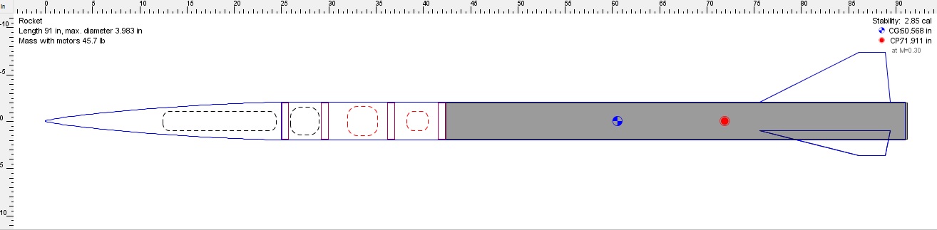
Mostly designed using OpenRocket. You cannot really tell from the picture but the NC shoulder goes back 10-12" (TBD), which would explain the position of the aft bulkhead. The forward mass object is the flight electronics and the smaller mass object is the cameras. Then comes the main parachute and lastly the drogue. The other parts are bulkheads and a engine retainer.
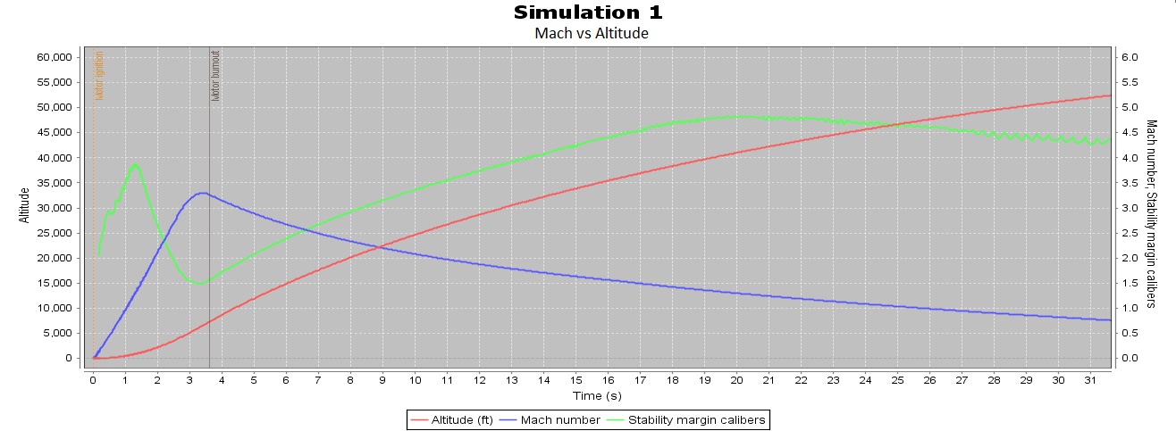
This graph is pretty self explanatory; altitude vs mach vs stability. Instead of showing the acceleration (peak of 40G) I thought it was more interesting looking at the before mentioned. On a side note, the vehicle experiences max Q ~3.25 seconds into the flight at an altitude of ~7kft and traveling faster than the speed of sound 3.5 fold. This is interesting sense most rockets go through max Q at transonic speeds. At max Q the rocket experiences ~1,300N of force. Note, this is note a as-built sim.
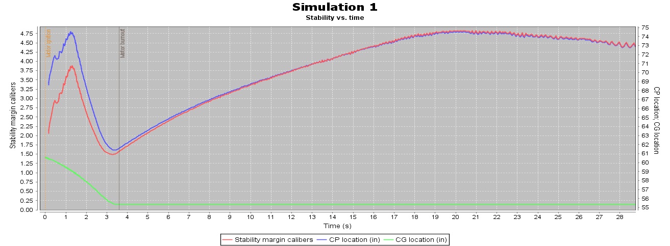
The stability of the rocket during the course of its flight never drops below ~1.5 calibers. This should allow enough stability for any error of margin and to minimally help protect stability drops due to changes caused by weather, AOA, etc. One thing that I would like to point out is that the CP moves in higher velocity flights down as normal, then rapidly up towards the CG, then eventually down again. The up movement towards the CG can be quite dangerous due to the fact that as the CP and CG near, the stability of the rocket drops. In my case the CP drops from about 74'' to 61'' in 2 seconds and approaches my CG with a distance of about 6". This is just one more rocket killer that must be dealt with to survive a higher velocity flight. Note, this is not a as-built sim.
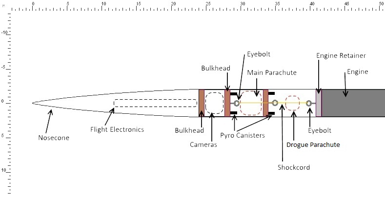
So here is my solution to DD out of a single airframe. I have not been able to successfully draw up a pretty CAD of this yet, so please bear with me. So the way this work is pretty basic and can be explained in two major parts. 1) The drogue parachute is housed in the AF in-between the NC shoulder bulkhead and the engine retainer. It is connected via 1500# Kevlar shock cord to standard forged eyebolts. The drogue is deployed via “high altitude capable,” BP at apogee. The pyro canisters house the BP on the aft NC shoulder bulkhead; this bulkhead has a “lip,” that prevents it from travelling into the NC shoulder due to the explosive event. Furthermore to prevent the bulkhead from travelling outside of the NC shoulder (due to the energetic pull from the shock cord during separation), a couple pins will bolt it to the NC shoulder until the main event. 2) The main parachute is housed inside the extend NC shoulder. There is a bulkhead forward and aft of the main parachute. The main parachute is also attached via 1500# Kevlar shock cord to a forged eyebolt. The forward bulkhead is bolted to the NC shoulder via counter sunk screws and houses two pyro canisters. These canisters house the BP that will shear the pins holding the aft bulkhead and thus eject the main parachute. The aft bulkhead has a whole in the origin, where the shock cord runs through. This prevents the bulkhead from ejecting in the atmosphere and also keeps the NC and AF together.
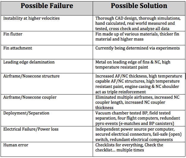
Put together a quick possible failure analysis.
Notes:
Here are some thoughts that I had and I will update this list as this thread progresses.
*As far as the sims go, I have been primarily using OpenRocket and RASaero. Although I do need to get a little more fluent with RASaero. RockSim is a nice piece of software but does not seem up to par for supersonic flights. I also have Solidworks, Autodesk and some ANSYS programs that I hope to use for CADs and flow analysis. I also need to get more fluent with them! I do not have finsim and unfortunately it is no longer being sold. If anybody would like to help me out with that then thank you very much")
*I would like to build on the knowledge of high mach flights in regards to temperature of various parts of the rocket due to aerodynamic heating. I would like to use some method of temperature indication on the NC, AF, and fins. I was thinking of using something like a welding marker or paint. Sensors may also be an option. I think it would be nice to have an approximation of how hot it is actually getting; this can help with construction techniques.
*I am providing some internal/external links to my personal website and the other threads on the forums. This may be redundant but will have more detailed information on the design, construction process, simulations, experiments, and post flight data. Please feel free to comment on it however you would like; any feedback is good feedback.
- coming soon
- https://www.rocketryforum.com/showthread.php?65106-Battle-of-the-Epoxies-A-Road-to-BALLS-Experiment (Epoxy experiment thread)
- https://www.ausrocketry.com/forum/viewtopic.php?f=10&t=4522
*This will naturally be tower launched. In the near future (as BALLS approaches) I will make a tower for this vehicle and will create a new thread showing that build.
Conclusion:
I am well aware that a flight of this magnitude has a high probability of failure and that a lot of things come into play on this scale. I am also well aware that some members may feel the need to post negative comments and I ask you to please refrain from that. I have not stated which engine I will use for this flight in hopes that I will not instigate any arguments or negative behavior in this thread. I do however encourage constructive criticism and will give it serious thought. I am also well aware that I could build a "low and slow," L3 rocket that would greatly increase the chances of success.... but that is not who I am. This flight is more about pushing my limits and knowledge and thus furthering my progression and the progression of the community; I feel this is more important than obtaining an L3 certification. I want to thank everyone for viewing this post and now lets go build a rocket.
Well I have been thinking about this rocket for about a year now and I thought it was about time to announce my intentions to build a L3 rocket for my certification at BALLS 23. Now most of you do not know me, I tend to keep rather quite on here. I try to post but I am ever so busy with school, work, my internship, and blah blah I am a bad TRF member lol. Anyways I will keep this short and simple (or so I thought). My plan is to build and launch a 98mm minimum diameter rocket..... successfully. The details will come all in good time. First, however I feel that I must name the people who have greatly contributed to amateur rocketry, pushed the envelope in knowledge and who have inspired others (at least in my case). Nic Lottering, Jim Jarvis, Mike Passaretti, Derek Deville, and the AeroPac group. There are many others who have done great things in this hobby but I am trying to keep the list as relevant as possible to this build. The documents that these men have released have been of great value and help to me and the community. I have learned a lot from these documents and it is in fact because of those documents that I am currently ready to begin my L3 rocket. Without their hard work and innovation I would not of been able to progress so rapidly. I plan on documenting this build very closely so to therefore help others as I have been helped. Now lets move on to the rocket!
Design:
So my basic design is rather simple. A MD 98mm ALL composite rocket that will fly on a 6GXL Engine.
1. First and foremost is to have a safe and successful flight; meaning no failures and the rocket survives and is recovered.
2. I will try to keep the rocket as simple as I can, to therefore reduce the probability of failure.
3. Everything about this rocket will be tested and tested again. I will calculate, experiment and simulate as much as I can to ensure that the overall flight will be successful.
4. NC is a 6:1 FWFG w/ aluminum tip. It is ~3mm thick with a 10'' shoulder that is of the same thickness.The extended shoulder allows for a more sturdy connection with the airframe. This not only increases the coupled strength of the NC/AF but also reduces the volume in-between the forward closure and NC shoulder bulkhead. This makes it easier to vent and hopefully will increase the chances of separation at apogee. The NC has been made to handle temps up to 600F. I have played around in the sims with the standard 5:1, 6:1, and 7:1. I have chosen to go with the 6:1 for better performance over the 5:1 and shorter length over the 7:1. However the 7:1 did seem to offer 0.01 more calibers of stability and ~500ft more of altitude. I chose FWFG for its mixtures of strength, lightweight, and RF transparency.
5. Airframe is FWCF that has also been made for temps up to 600F. The airframe is 66'' in length X 4'' in diameter and is ~3mm thick. It is also a single continuous airframe. I have looked at failures that occurred during high mach flights and I believe some of them were due to the coupled airframes. So my plan is to eliminate that structural weakness in the airframe and hopefully increase the percentage of success. Not only have I designed a single airframe but the entire vehicle is reinforced. The thickness of the NC, NC shoulder, and the airframe is ~3mm thick. Furthermore because of the NC shoulder and the engine hardware, the entire rocket is almost completely "triple walled." The length of the entire vehicle is 90'' and the true OD is ~3.983''.
6. Engine retention will be either the Aeropack MD retainer or a "forward thrust plate retainer," piece that I had machined for MD flights. Both pieces are 6061-T6 aluminum and both sit in front of the engine. They are retained to the AF with epoxy and counter sunk screws.
7. The basic thought on the fins are that they will be as small as reasonable stability allows to reduce the aerodynamic loads they will experience. They will be ~3mm thick of G10 FG plate that is layered with 3k aerospace grade CF and also capable of 600F. Now the aerodynamic loads on this flight are a force to be reckoned with, therefore to prevent fin flutter (all types) I am doing full t2t with 3k aerospace grade CF. I plan on doing 3 layers but will be doing some experiments with static loads and heating to see if I require more layers. Prior to this I am doing epoxy, surface prep., and additive testing (link can be found in notes section). Another big concern is delimitation of the CF that is due to the aerodynamic heating. I have spent some time looking at ablatives and have opted out of using them. I feel that ablatives however effective are just too much of a pain. I would like the rocket to be reusable without having to re-coat it with an ablative and having any downtime. I also am concerned with the rate of which they burn off requiring more testing and calculations to ensure that I have the correct thickness to be burned. Also ablatives can leave part of the rocket uneven and I would like to keep the rocket as aerodynamic as possible throughout its entire flight. So I am going with Nic's idea that he used on Mad Max. That is, I am putting metal over the leading edges of the fins… I think this is brilliant! I mean we put a metal tip on the leading edge of our composite NCs, why not on the leading edges of our composite fins?! Thank you Nic for that.
8. Recovery is DD out of a single airframe. This takes out a weakness in the design that could of otherwise been fatal. Most likely the parachutes will be a small 18'' drogue and a 72'' main deployed via "high altitude capable," BP. The parachutes Cd is 1.6 and 2.2, respectfully. This creates a descent rate of ~80ft/sec and 28ft/sec, respectfully. This is all assuming a total rocket weight of 15lbs. I came up with a way to go about DD from a single airframe without the need of something like an AARD, cable cutters, or a tender descender. It is a very simple design and some what of a traditional manner. The biggest points of this system are that it moves the main into the NC and the drogue in-between the NC shoulder and the engine retainer/thrust plate. The only new items that are introduced, are another bulk plate and thus it is more like a traditional setup v. something that requires your main parachute to float out in the atmosphere during descent from apogee. I hope that this creates a more simple and reliable setup. I will go into slightly more detail with some CAD drawings and explanations later on in the thread. I have two other rockets that are setup for this but I have yet to fly them. The sole point of one of these rockets is test out the new DD setup to ensure it is reliable; it will also be tested in a vacuum chamber. I will update you all with the results once all that has been accomplished.
9. Electronics are most likely going to be TeleMega x2, BRB 70cm GPS x1, stratologger x2. That gives me 2 primary flight computers, 2 redundant flight computers, and 3 GPS/telemetry systems. All of which will be operating on different frequencies to avoid interference. This system will also be vigorously ground tested. I have some Ravens laying around and might use those, but as of now that is the setup I am thinking of. Every board will have its own power source and the 2 primary flight computers will each use 2 batteries. 1 for the pyros and 1 for everything else; the power sources will be LiPos. All flight computers/GPS systems will be mounted in the NC. I will have on board cameras on this flight and the cameras will be GoPro H3 x2. They will be housed in the shoulder of the NC. I would like to play with mirrors to get some cool angles for flight video but I do not want to increase drag. If there are any ideas on how to avoid this then please share!
10. I will paint this rocket with high temperature paint (1500F). My goal with the paint is not so much for form but more so function. I am hoping the paint will act as both a insulator and an ablative. This will hopefully eat up some dangerous energy and hopefully aid in preventing delamination and structural weakening. I will do at least 3-5 layers of paint to make it more effective. As far as the colors and style of the paint job... idk. I will think about it once I get there.
Mostly designed using OpenRocket. You cannot really tell from the picture but the NC shoulder goes back 10-12" (TBD), which would explain the position of the aft bulkhead. The forward mass object is the flight electronics and the smaller mass object is the cameras. Then comes the main parachute and lastly the drogue. The other parts are bulkheads and a engine retainer.
This graph is pretty self explanatory; altitude vs mach vs stability. Instead of showing the acceleration (peak of 40G) I thought it was more interesting looking at the before mentioned. On a side note, the vehicle experiences max Q ~3.25 seconds into the flight at an altitude of ~7kft and traveling faster than the speed of sound 3.5 fold. This is interesting sense most rockets go through max Q at transonic speeds. At max Q the rocket experiences ~1,300N of force. Note, this is note a as-built sim.
The stability of the rocket during the course of its flight never drops below ~1.5 calibers. This should allow enough stability for any error of margin and to minimally help protect stability drops due to changes caused by weather, AOA, etc. One thing that I would like to point out is that the CP moves in higher velocity flights down as normal, then rapidly up towards the CG, then eventually down again. The up movement towards the CG can be quite dangerous due to the fact that as the CP and CG near, the stability of the rocket drops. In my case the CP drops from about 74'' to 61'' in 2 seconds and approaches my CG with a distance of about 6". This is just one more rocket killer that must be dealt with to survive a higher velocity flight. Note, this is not a as-built sim.
So here is my solution to DD out of a single airframe. I have not been able to successfully draw up a pretty CAD of this yet, so please bear with me. So the way this work is pretty basic and can be explained in two major parts. 1) The drogue parachute is housed in the AF in-between the NC shoulder bulkhead and the engine retainer. It is connected via 1500# Kevlar shock cord to standard forged eyebolts. The drogue is deployed via “high altitude capable,” BP at apogee. The pyro canisters house the BP on the aft NC shoulder bulkhead; this bulkhead has a “lip,” that prevents it from travelling into the NC shoulder due to the explosive event. Furthermore to prevent the bulkhead from travelling outside of the NC shoulder (due to the energetic pull from the shock cord during separation), a couple pins will bolt it to the NC shoulder until the main event. 2) The main parachute is housed inside the extend NC shoulder. There is a bulkhead forward and aft of the main parachute. The main parachute is also attached via 1500# Kevlar shock cord to a forged eyebolt. The forward bulkhead is bolted to the NC shoulder via counter sunk screws and houses two pyro canisters. These canisters house the BP that will shear the pins holding the aft bulkhead and thus eject the main parachute. The aft bulkhead has a whole in the origin, where the shock cord runs through. This prevents the bulkhead from ejecting in the atmosphere and also keeps the NC and AF together.
Put together a quick possible failure analysis.
Notes:
Here are some thoughts that I had and I will update this list as this thread progresses.
*As far as the sims go, I have been primarily using OpenRocket and RASaero. Although I do need to get a little more fluent with RASaero. RockSim is a nice piece of software but does not seem up to par for supersonic flights. I also have Solidworks, Autodesk and some ANSYS programs that I hope to use for CADs and flow analysis. I also need to get more fluent with them! I do not have finsim and unfortunately it is no longer being sold. If anybody would like to help me out with that then thank you very much
*I would like to build on the knowledge of high mach flights in regards to temperature of various parts of the rocket due to aerodynamic heating. I would like to use some method of temperature indication on the NC, AF, and fins. I was thinking of using something like a welding marker or paint. Sensors may also be an option. I think it would be nice to have an approximation of how hot it is actually getting; this can help with construction techniques.
*I am providing some internal/external links to my personal website and the other threads on the forums. This may be redundant but will have more detailed information on the design, construction process, simulations, experiments, and post flight data. Please feel free to comment on it however you would like; any feedback is good feedback.
- coming soon
- https://www.rocketryforum.com/showthread.php?65106-Battle-of-the-Epoxies-A-Road-to-BALLS-Experiment (Epoxy experiment thread)
- https://www.ausrocketry.com/forum/viewtopic.php?f=10&t=4522
*This will naturally be tower launched. In the near future (as BALLS approaches) I will make a tower for this vehicle and will create a new thread showing that build.
Conclusion:
I am well aware that a flight of this magnitude has a high probability of failure and that a lot of things come into play on this scale. I am also well aware that some members may feel the need to post negative comments and I ask you to please refrain from that. I have not stated which engine I will use for this flight in hopes that I will not instigate any arguments or negative behavior in this thread. I do however encourage constructive criticism and will give it serious thought. I am also well aware that I could build a "low and slow," L3 rocket that would greatly increase the chances of success.... but that is not who I am. This flight is more about pushing my limits and knowledge and thus furthering my progression and the progression of the community; I feel this is more important than obtaining an L3 certification. I want to thank everyone for viewing this post and now lets go build a rocket.
Last edited: