98mm Min Dia L3 Build

The Rocketry Forum

Help Support The Rocketry Forum:

This site may earn a commission from merchant affiliate links, including eBay, Amazon, and others.
A5tr0 An0n,

Did you send in your 50K paperwork to the TRA Class 3 Committee?

Mark
Yes I did Mark. Actually had a descent conversation yesterday with Kent; thank you for checking up though. Very much appreciated.


I will be updating this thread soon.


Mat
 
Last edited:
Time to catch up on this thread. This build has become a roller coaster full of ups and downs, so let the ride begin. Seeing as this is my L3 build I am going to document it a little more than I would care to.

I chose a four fin design over a three fin design. So far the only flights to survive a MD N5800 have been three fin vehicles. The reason I choice four fins is because it appears that the dynamic stability provided is greater and that this allowed for smaller fins thus reducing the aerodynamic loads that would be applied to them. I thought that this was important seeing as I chose against using metal fins. I also decided on a fin thickness of 0.125" with the material being carbon fiber. I also decided on having them CNC cut to ensure the proper measurements that I wanted. I wasn't worried about any imperfections via cutting them by hand. I have built a fin can to Mach 3 before that was far less than ideal… it survived the ascent. My major concern was the numbers I had been playing around with (as far as dimensions) and how accurately I would be able to get to those numbers by hand. I was already toying around on the danger side in terms of the fin's measurements so I thought it be fit for the fins to be as close as possible to on paper and thus the CNC was my choice.

I took the stock fins and then layered them with 4 layers of carbon on each side. This brought my fin to ~0.2" thick. The laminating system I used was my regular Cotronics 4461, which is good to 500F. Making the choice to use all carbon and having them that thick was mainly to ensure survivability, especially if the vehicle went to a "bad," alpha. This is my L3 after all and I would like it to survive, so no need to push the envelope here. Just to state something, thinner fins with FG cores have survived a lot faster than I intended to go… I went the conservative route.


14972690937_4797f82215_c.jpg

Carbon Fiber fabric.


14972685878_b09d3cfd18_c.jpg

Taped off for each fin. The fins received 32 layers of carbon.


14972669377_8d651191ed_c.jpg

Fabrics cut, Carbon wetted, ready to flip and repeat.


15156257441_f298abbea6_c.jpg

Other side wetted and peel ply/breather applied. Ready to be bagged.


14972496619_7530fce0c3_c.jpg

Bagged. Pulled -27"Hg. Some wrinkles… will fix those when not taking pictures.


15156244621_dc41e2b06f_c.jpg

Close up right after pulling vacuum.


15220074755_6586d44e6e_c.jpg

Done. Now time to trim off that excess carbon fiber.


15159227385_a0ba280c0c_c.jpg

All trimmed. I used a bandsaw to get it as close as possible to the edges of the fins. Next I took a random orbital sander and applied it to the root chord only. The idea behind this was to shorten the work needing to be done by hand.


15158820372_cf4d67df10_c.jpg

I took the root chord down with the random orbital sander until it looked like the above picture. I chose only the root chord seeing as the other sides of the fins would be easier to throw out of whack.


15159220985_4cfdd5e616_c.jpg

To bring the rest of the layered carbon down I taped a piece of sandpaper to a flat piece of MDF board and then oriented the fins on all sides while I pressed and sanded. I did this one by one and then squared them all up together at the same time. Honestly there was really not much to square up, but I did it nonetheless.


14972472339_c7ef9637ef_c.jpg

Looks like this once all the excess carbon is removed.


14972523010_57779f643e_c.jpg

All done.


The fins now need to be beveled. I would like to give credit to butalane and oberth for the fin beveling tool they showed in their thread. I had a sliding jig that I made that could be used on table routers and table saws to bevel fins. This method produced good results but made me uneasy (I have had a fin fly at my face). I have also hand bevelled fins both with regular sandpaper and on a belt sander. I wanted a new "easier and safer," method. I built a mock up of their jig; it is basically a router table (uses a compact router) that is the bevel jig itself and the results were great. It was quick, easy, precise, and safer than some of my other methods before. I will be using this for beveling from now on.


15219686582_3fa6f4644a_c.jpg

Bevel time.


15219686972_af72247eb0_c.jpg

This is some of the now "fin dust," after about two fins.


15197049396_3acf1e8e10_c.jpg

All done. It might be hard to see but the bevel is about ~0.7" from the edge.


15175340137_4cdf336885_c.jpg

Another shot, post beveling.


15355503695_4d078107af_c.jpg

Before and after.


15355482075_49ea6d1eb2_c.jpg

Another angled shot for comparison.


Cheers!
 
Last edited:
Before tacking on the fins I wanted to square away the prevention of delamination. From my observations the majority of delamination occurs at the leading edges of the fins and at the point where the root chord and the swept part of the fin meet (the very front of the fin). Nic has successfully used SS on the leading edge of his fin to prevent delamination on his MD N5800 flight and that was the method I chose ,as mentioned before. 316 SS has a BTU in / Hr ºF Ft^2 of about 10 @212F and a melting point between 2500 – 2550°F. The idea for a SS cap was not to insulate it per se but to also prevent the fibers from pulling out due to the energetic air flow.

I settled on 316 SS and bought two different thicknesses of shim stock. I bought 0.015" and 0.005" thick sheets. As it turned out the 0.015" shim stock is too thick and leaves the fin tip radius unpleasantly thick. It is also a pain to work with. The 0.005" thick shim turned out to be too thin! It wrinkled in a couple of places and obviously that is not what I wanted so I pried it off and removed the left over epoxy. Imagine trying to fold a sheet of aluminum foil over the beveled edge of another object… it will wrinkle throughout the sheet. This left me slightly unhappy; instead of getting my hands on the proper thickness of shim stock (I do think the key to success is in the thickness) I opted out for a method in which I have been wanting to do for some time now…. more on that later.


15216990801_f444889df3_c.jpg

In a last resort to prevent the wrinkles I used clips on all the real estate available. I later had to remove the rubber ends to place into the oven for curing. Sadly no joy, this was the point in which I said "forget about the metal," (more of that later)! Oh and yes the smaller of the grains is a N5800 grain… I am sure someone would ask. xD


In conclusion on the metal caps, they are a great idea (same as the metal on the NC tip) but it just didn't work out for me this time. No worries though I am a fan of composites anyways.


Disclaimer:
I am still traveling home from BALLS and this is the only photo that I have of the metal caps on my computer. I will update it as soon as I get home.
 
Nothing special here, just tacking on fins. I used Cotronics 4525 to tack them on; each fin was cured at 250F for 5 minutes. Used the normal method of printing out a template with 4 marks each at 90 degree intervals and then transferred that onto the airframe. Everything was marked and then taped off to prevent making a mess with epoxy. I added graphite powder and west systems 404 adhesive filler to each batch of epoxy by 10% mass.

As far as surface preparation goes: I wiped all the parts with acetone prior to sanding, then sanded with 60 grit and 150 grit, then wiped off all parts again with acetone. During the surface preparation process at all times, gloves were worn and change frequently. This method of fin alignment has been used to about the expected velocity of this flight, so I have no worries that it is as true as needed.


15219246942_3ee5e15c2f_c.jpg

Surface prepped, cleaned and ready to go.


15033054647_4f7b3f3487_c.jpg

First fin tacked on.


15219625595_09331a6efb_c.jpg

Second fin tacked on… you get the idea.


15352953961_87961b9a8e_c.jpg

All fins tacked on. Starting to resemble something they call a rocket.


15356151675_1c4f84904a_c.jpg

Another angle.


15333140636_ea3cc890d0_c.jpg

Just taking a step back.


15175106509_bd1ec38d78_c.jpg

And another. Just FYI, that is not the actual cone for this rocket. It was just the closest for pictures sake.


Yes I know my shop is a mess... I had no time to clean it all up before the launch date. I didn't get all the parts in until about 2 1/2 weeks before my departure date, part of the roller coaster ride was staying up till ~4am each night for over 2 weeks in a row.
 
Last edited:
That is just awesome, I cant wait to see it in person.


Alexander Solis

Level 1 - Mariah 54 - CTI-I100 Red Lightning Longburn - 6,345 Feet
 
Updated last two posts with another picture, anyways back to business.

Per the original plan, I wanted to do this build without tip-to-tip but I was concerned that big fillets may not be enough to keep the fins on. I planned on using aluminum brackets that would be bolting the fins directly to the airframe via countersunk bolts that run from the inside out. I think this provide a more secure attachment vs bolting them from the outside in. After bolting them into place I planned on laying down large carbon fiber reinforced fillets over the brackets. Seemed like a good plan and I was overly confident that this method would hold the fins on as it has done in the past.

Next I ordered the material for the brackets: Aluminum 7075-T7351 7/8" x 7/8" x .065" x 72". This is stronger than the common 6061 but a little harder to work with. The plan was to make a template for the drill holes, drill the hole into the metal, then cut the brackets to spec, bend them to the shape of the airframe, tack them on, and countersink the airframe from the inside going out. All of this essentially went as planned except bending the fins to shape. I was going to build a jig to hold the brackets in place while Al. bar stock sat on top and I pressed it down onto the brackets, thus bending them to the desired shape. Well I didn't have any extra suitable metal laying around and had no time to get it in time to make the jig to help shape the brackets. I tried with wooden blocks but the wood started to crack and thoughts of wooden shrapnel caused me to back off.

So here is where things start to go downhill, roughly less than 3 days before I am suppose to depart for BALLS. I decided at this point I will just tack them on without bending them to shape. This left ~0.125" on each side of the bracket and I thought meh, I will just fill that with thickened epoxy. Well that part worked, but to save more time in construction I had come up with a "new idea,". Instead of having to line all the holes up for the bolts that go through the fins, I just drilled the holes in one side and then tacked them on and attempted to drilled through the fin and other side of the bracket at once. In theory this would save time and work as good as needed. Well here is where the ride started going down hill. I had a simple jig to hold everything in place while I took the drill press to each "predrilled hole." The bit went through the fin, through the built up epoxy and then pushed the opposing side bracket off! I thought maybe this was a one time occurrence so I tried with another bracket and the same thing happened again. I quickly realized that this was NOT going to work. Here is when I said "forget about the metal," a second time. This all happened about 12am and in all my glory, I decided the brackets needed to come off by means of a hammer and chisel. This led to another set of series of unfortunate events… the hammer and chisel ultimately knocked all the tacked on fins off the airframe, but it did successfully detach the brackets (have to look on the bright side). So here I sit early in the morning less than 3 days from BALLS with no fins on the airframe………...


15176579299_d58e26461c_c.jpg

Metal stock clamped in place and ready to be cut via gravity.


15176645730_17974d3c12_c.jpg

Mid cut.


15175105249_a44a25fec0_c.jpg

Here are the brackets. I ended up shorting the front pairs just a bit.


15176784377_c204270751_c.jpg

The result of shorting them ended up with a product as such.


15175339137_ec821ddaeb_c.jpg

It is not exactly level but here you can see the ~0.125" gap between the brackets and structure.


15363300655_be19e8f3b4_c.jpg

Marked off and ready to be tacked on. Pencil is not as easy to see but it is there.


15175277558_4a1b15d0cc_c.jpg

Brackets tacked on, gently wiped down, cured @250F for 5 mins, and then cleaned up with a Dremel.


15361862905_d50db3be1c_c.jpg

Here you can see the countersunk airframe. Maybe it was just me but countersinking from the inside out is a little trickier than it looks.


15175335747_c272a72c7e_c.jpg

This picture was before attempting to drill the holes through the fins and the opposing side of the brackets. At this point I still believed everything was OK.


15177211537_0ab2a2213b_c.jpg

After taking off the brackets. You can see some carbon that it took off of the fins; this slightly enforces the idea behind the structure failing first, before the epoxy.
 
Last edited:
motion to put this on the side of the rocket

02-Astro-The-Jetsons-famous-pets-from-TV-and-movies-1.jpg


Make sure to put some grease on those brackets your aluminum rails and aluminum brackets will gall on lift off.

Have you tried to fit your motor case? Those screws look a little proud.
 
Sinfuldarklord,

Thanks.


Flynfrog,

The idea was to fillet over them, however the rocket leaves the tower extremely fast and I really have no concern about any spin while it remains inside the tower. The case also fit fine inside the airframe… obviously that is checked xD. The reason they look that way is actually because the countersunk hole is slightly larger than the head of the screw. It is kind of hard to see that in this picture.
 
Before I post the next post I guess it is fair to everyone for me to state something. As mentioned in the very beginning I had little concern on actually obtaining my L3 per se. To clarify, this flight was about this flight and not much more… the L3 was just the excuse to be able to do it on my own. The whole level system doesn't mean much to me. This project started about a year ago and over the time leading up until now I have done other projects one of which caused me to out grow this build. For Airfest this year Propechy and I built a ALL composite rocket that flew on an EX N6000 to ~M3. This was a composite motor case, composite fin can, and a hell of a motor that ran at HIGH pressures. It survived the ascent and honestly the fin can was less than perfect. The fins were on with big fillets and 3 layers of tip-to-tip and no major measures were taken to prevent the leading edges (no fabric was on the edges however). This rocket was built ~2 weeks in advance and the last 3 days consisted of being up until 5:30am and that included drilling in the hotel room the night before.

The reason I bring this up is this caused me to slightly lose interest in this flight. The interest has been renewed after recent events at BALLS but that will be mentioned later in the thread. I am trying to keep it as close to chronological as possible. If you are interested in the aforementioned flight see below.

[video=youtube;LFAPnk16x48]https://www.youtube.com/watch?v=LFAPnk16x48[/video]

14953191137_c6218769d5_c.jpg


15139721155_37789649b2_c.jpg
 
...For Airfest this year Propechy and I built a ALL composite rocket that flew on an EX N6000 to ~M3. This was a composite motor case, composite fin can, and a hell of a motor that ran at HIGH pressures. It survived the ascent and honestly the fin can was less than perfect. The fins were on with big fillets and 3 layers of tip-to-tip and no major measures were taken to prevent the leading edges (no fabric was on the edges however)....

Mat,

I think you and Steve are being generous in your performance estimates. First off, the motor pressure isn't THAT high, its ~1100PSI peak and there is no way that rocket hit M3. Keep in mind that the rocket you flew is very close to the original HoneyBadger only heavier, with almost 1000Ns less impulse, and flown at a lower elevation. That rocket hit M2.4 and had no thermal protection whatsoever nor even high temperature capable materials. At best this rocket performed identically - M2.4 - but to me that is a stretch. Even the second HB, which was leaps and bounds better than first and yours in terms of mass optimization only reached M3.1. I'd guess the composite case you guys flew weighed as much if not more than the entire HB2 rocket.

Given that these four rockets used the same propellant in the same grain config (-2in prop length for Steve's) I think for performance comparison they are in the same family.

I only mention this because it seems like your are justifying capability with this flight assuming the performance is a lot greater than it was (and that the fins did in fact stay on and weren't the cause of the shred which is another stretch). Don't kid yourself there is a big difference between M2.4 and M3 and between (Ignore the outlandish number given in that video) a 15,500Ns N5500 and an N5800.
 
Last edited:
Mat,

I think you and Steve are being generous in your performance estimates. First off, the motor pressure isn't THAT high, its ~1100PSI peak and there is no way that rocket hit M3. Keep in mind that the rocket you flew is very close to the original HoneyBadger only heavier, with almost 1000Ns less impulse, and flown at a lower elevation. That rocket hit M2.4 and had no thermal protection whatsoever nor even high temperature capable materials. At best this rocket performed identically - M2.4 - but to me that is a stretch. Even the second HB, which was leaps and bounds better than first and yours in terms of mass optimization only reached M3.1. I'd guess the composite case you guys flew weighed as much if not more than the entire HB2 rocket.

Given that these four rockets used the same propellant in the same grain config (-2in prop length for Steve's) I think for performance comparison they are in the same family.

I only mention this because it seems like your are justifying capability with this flight assuming the performance is a lot greater than it was (and that the fins did in fact stay on and weren't the cause of the shred which is another stretch). Don't kid yourself there is a big difference between M2.4 and M3 and between (Ignore the outlandish number given in that video) a 15,500Ns N5500 and an N5800.


butalane,

Thanks for the post. I can see that… it jumped off the pad but looked like it stop accelerating quickly. Plus all the simulations IMO seemed to be a bit high. The only motor file I had to work off of, is with the data that was given to me; will PM you in regards to the motor file. I consider 900psi high but was under the impression that it was running higher. Honestly the only thing I did in regards to the motor, was what I was told to do lol (I am brand new at motor building).

The cause of fault is believed to be the nose cone tip coming off, it was not glued in place and just hand tightened. Upon recovery of the nose cone the tip was off to the side with a bent bolt. I understand your point and understand things do not change linear, in respect to one another as Mach increases. That being said I have seen some methods that I questioned survive some interesting flight profiles. The fins on this rocket were also huge, so even if we did call it M2.4 (probably a lot more accurate as it turns out than M3) I think that is just a tad bit impressive.

So it is a N5500 not a N6000 and 15,500Ns? That is a bit of a difference from what I had, but I trust your numbers more obviously. We only had an approximate motor file...
 
So...

With the motivation of Prophecy, I decided to build a "NEW," rocket in ~2 days time and then hit the road for BALLS. This may sound familiar to some. Prophecy really deserves a lot of credit here, without him I would of never proceeded. I would have just scratched the build and started over from scratch… thats my nature. That is something very easy to do especially when you have just done a very similar project and are helping on a scaled up one.

So my new plan of attack was to go with what I knew best, big fillets with tip-to-tip over them. Funny how things got back to me… anyways this strangely put me back into my comfort zone and would make this more of a true all composite vehicle. In order to get the fins/airframe ready for fin tack on, required some HEAVY removal of Cotronics 4525 epoxy. After about 2 hours of electric sanding with a random orbital sander and about twenty five 60 grit discs later, I was back at square one. I tacked the fins on with the exact same method as used before right after removing the excess epoxy and cleaning them up.


15177049487_6f92447bc6_c.jpg

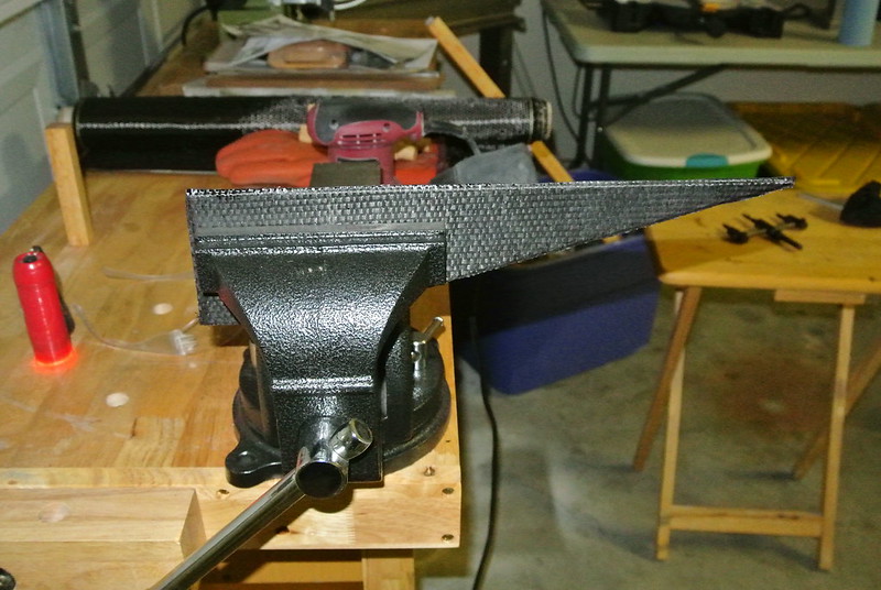
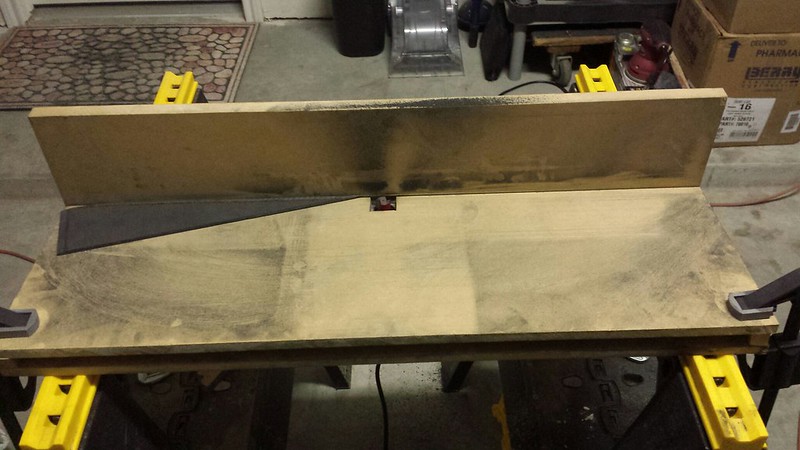
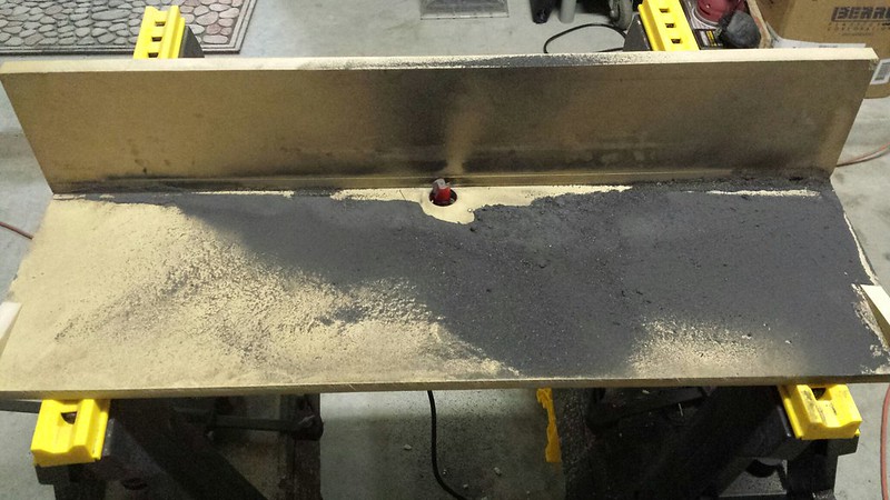
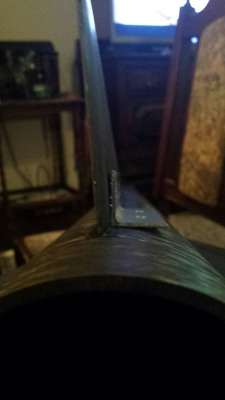
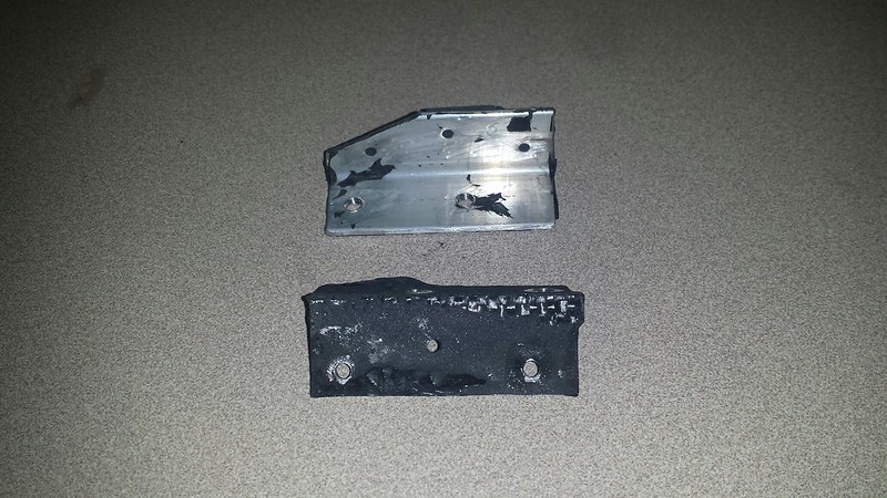
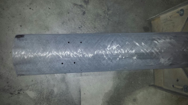
The airframe after taking down all the built up 4525… not an easy thing to do.


15340553416_0a0cd090c8_c.jpg

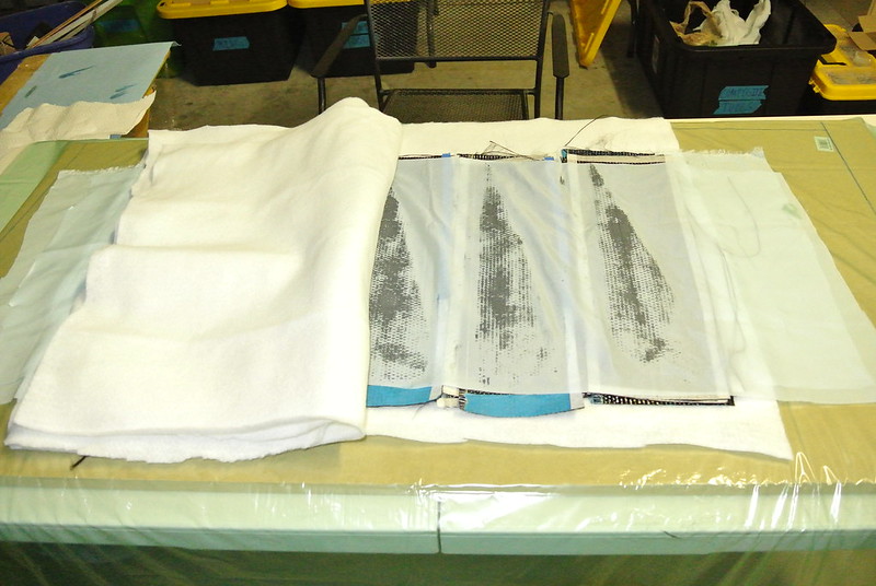
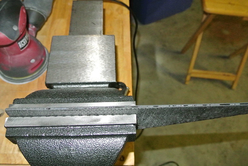
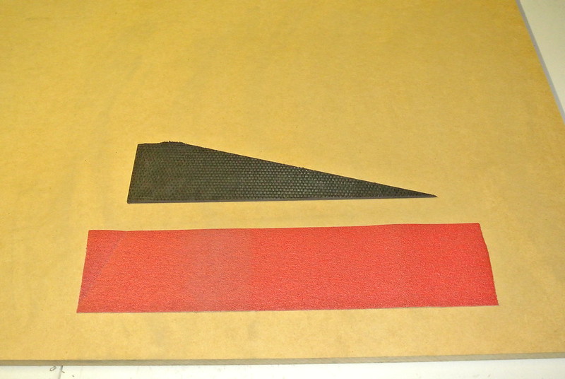
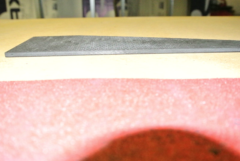
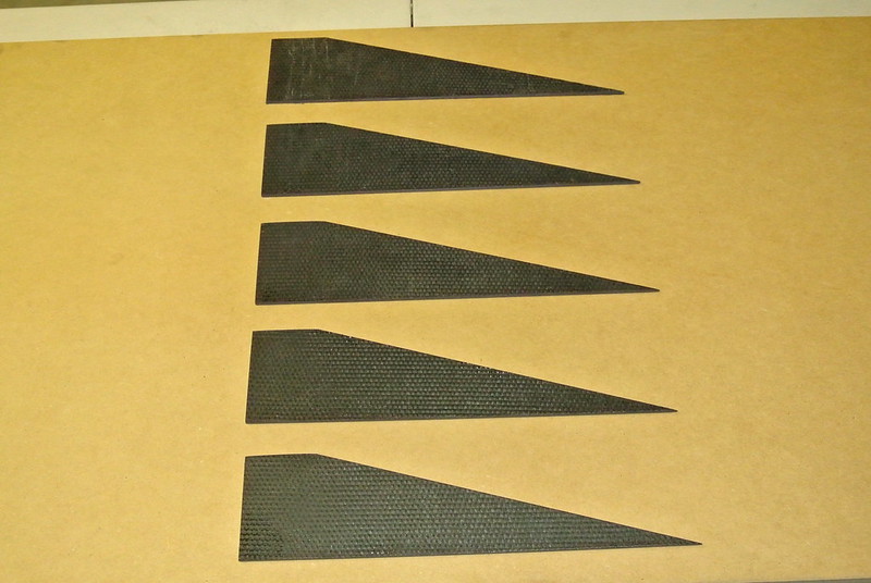
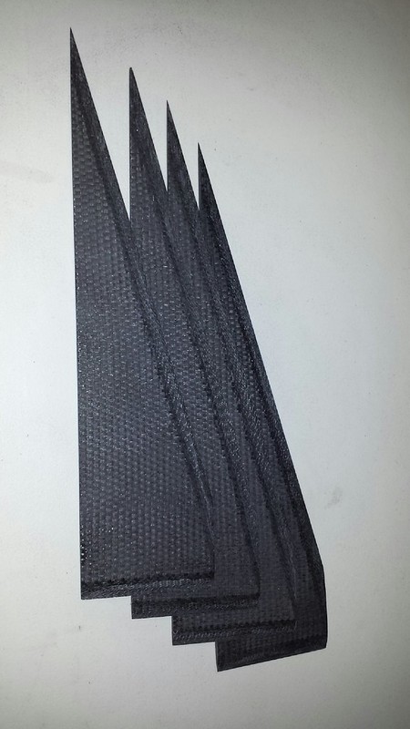
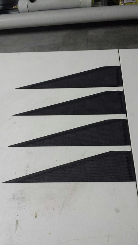
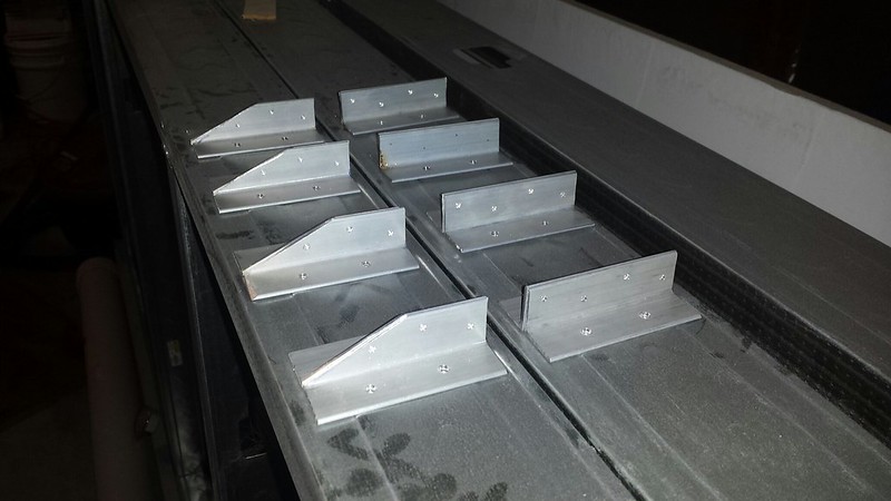
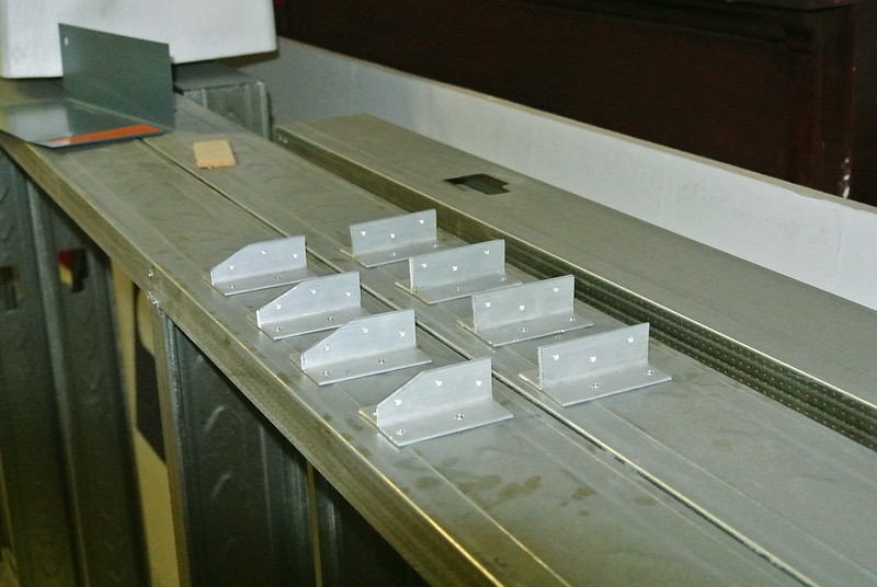
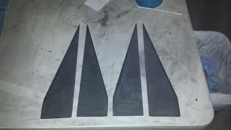
The fins after "cleaning up," the 4525.


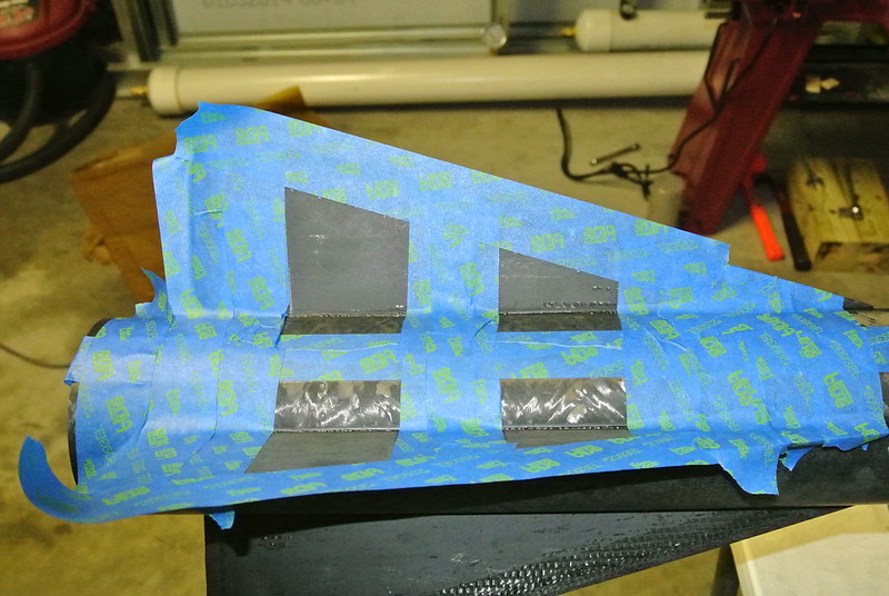
So the next step was to measure, mark, and tape off where the fins were planned to be tacked on. So here again is where I shoot myself in the foot. Instead of mixing epoxy and going with my regular method of filleting, I thought it would be a great idea to push carbon fiber strands into the fillet instead of having random oriented fibers. So the plan was to put down 3/4 of the fillet, push CF into the fillets and then lay the remain 1/4 of epoxy over it to aide in smoothing them out. Sounded good except I didn't have enough epoxy, it was harder than I thought (and messier than I thought), and I didn't check the length of my fibers that my girl had cut or me. All my fault for trying to do this in a rush… I know. After the first 2 fillets I decided it would be easier to get them as close as possible and then sand the excess fibers off and smooth the fillets. Wrong! It helped a bit but was no easy task. The fillets came out big and ugly and it was a good learning process. I had told myself before I would not launch this way again… but I did. I mean it this time… if a project is not done the trip is canceled. Enough ranting. So the fillets had areas that needed to be filled (to challenging to take it all down). It took about 2 hours to do all the fillets for the rocket. That includes the 5 min at 250F cure but does not include the partially failed attempt at sanding them down.


15175110919_54cbdfd1eb_c.jpg

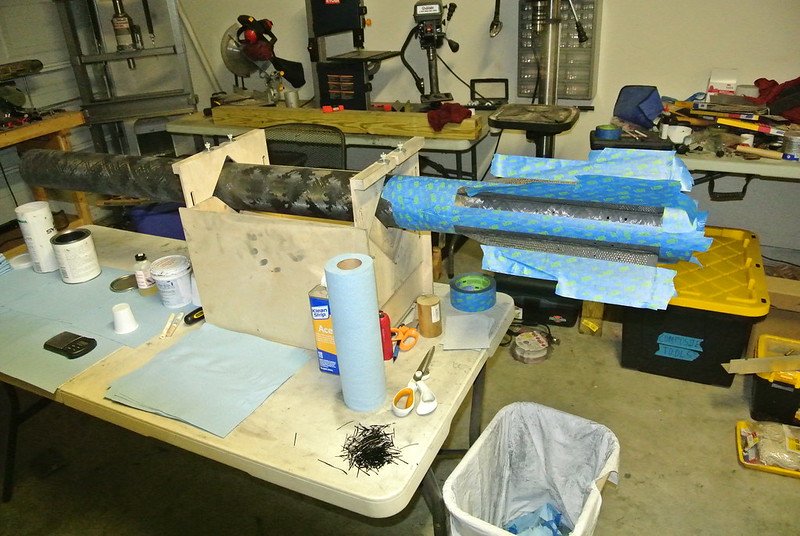
All the fins tacked back on. Area is measured, marked, and taped at 0.75" for the soon to be fillets.


15175362608_dfc08f876e_c.jpg

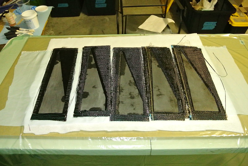
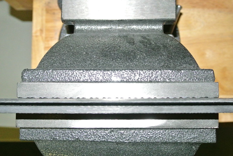
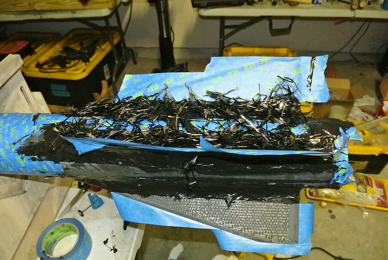
Fillet partially laid and carbon fiber strands laid on top to be pressed into place. I ended up pulling out about half of the fiber that you see there. Started out laying them nice then it got messy and hard to a just let them fall as they would. Defeated the whole purpose of this, I know.


15175173709_f3634a2b16_c.jpg

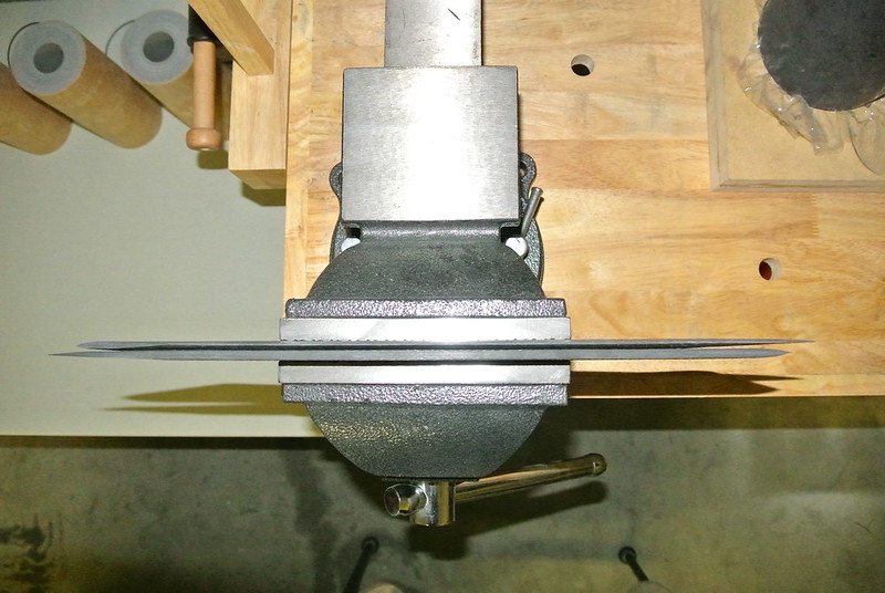
Pressed down and what little epoxy that I had was laid on top.


15338911436_be39067edc_c.jpg

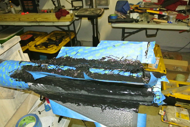
Sanded and you can see the little gaps that I was talking about. Ended up filling them with more epoxy.


15175391297_5fec8fa6da_c.jpg

Another shot. The carbon fibers really made a mess… good lesson though.


15338900406_6e1f12f3f0_c.jpg

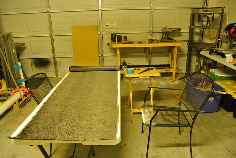
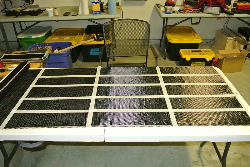
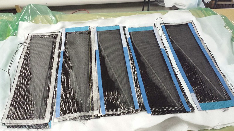
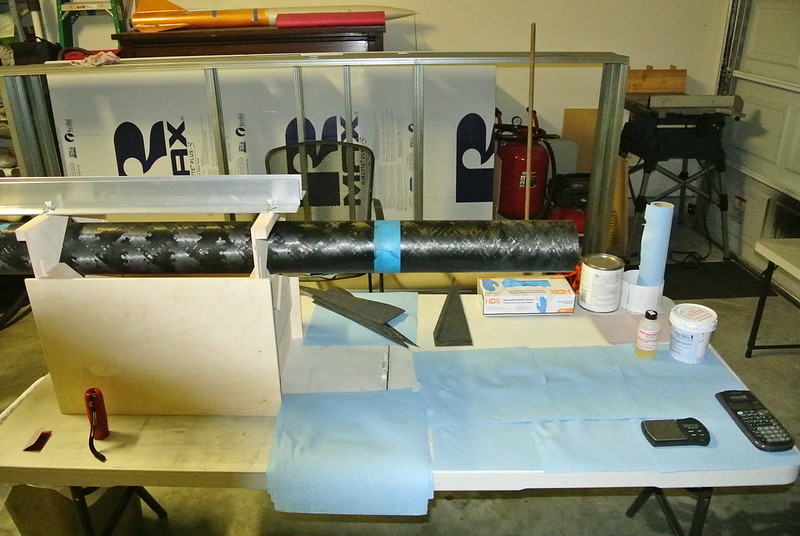
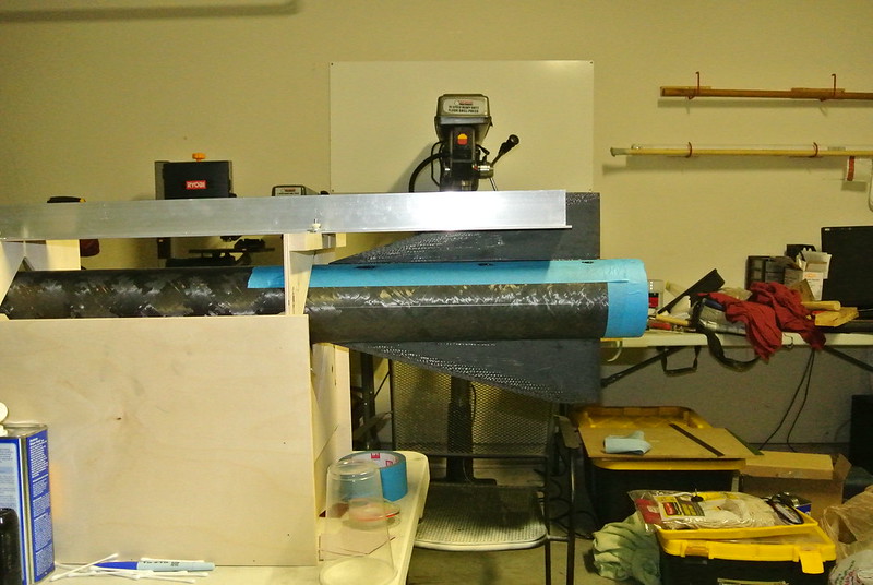
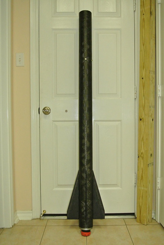
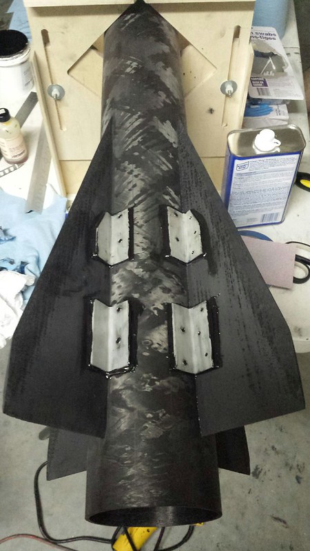
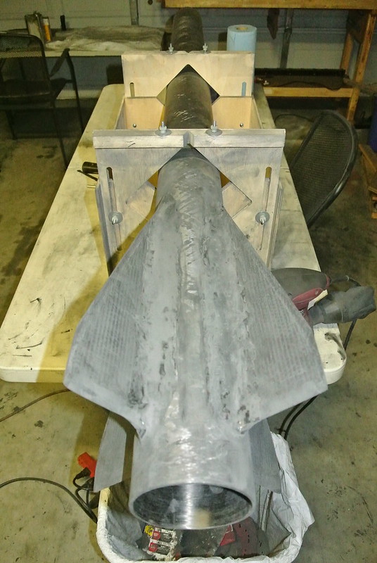
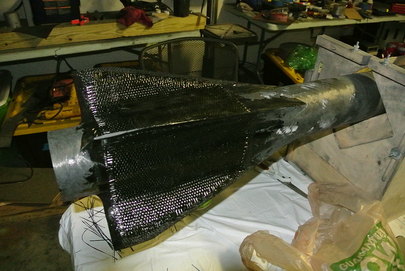
4 layers of tip-to-tip were applied with slightly standard 3k fabric. At this point all I had available was Aeropoxy so it is what I used. Not my favorite but if done in a decent manner could work.


15358730931_e006b88579_c.jpg

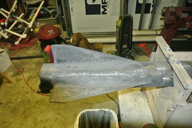
Another shot of the tip-to-tip.


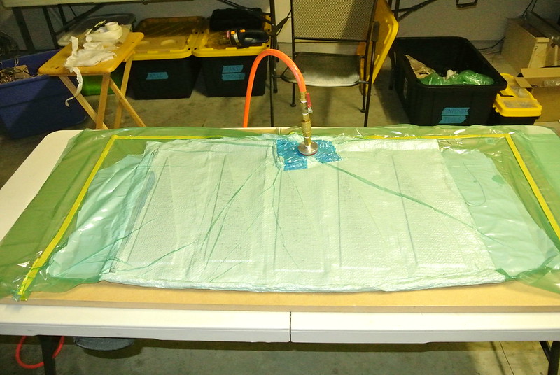
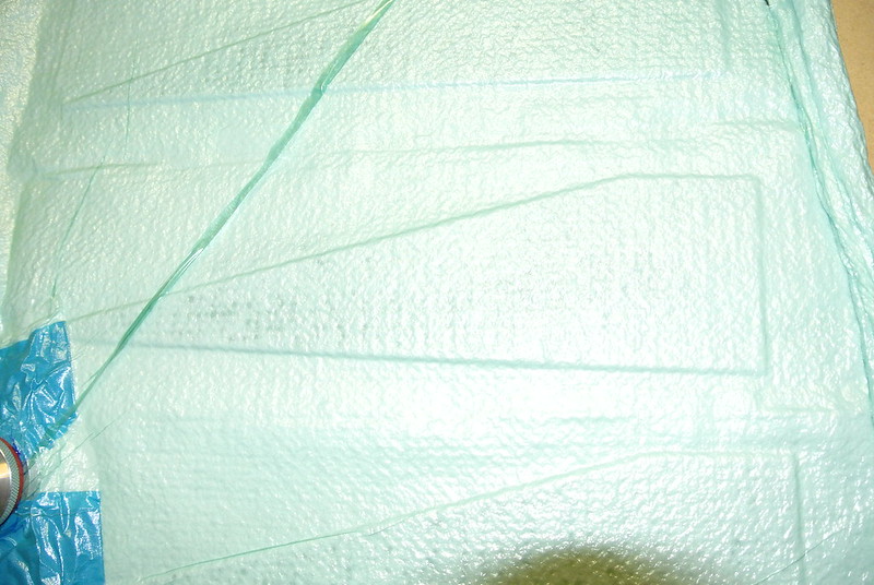
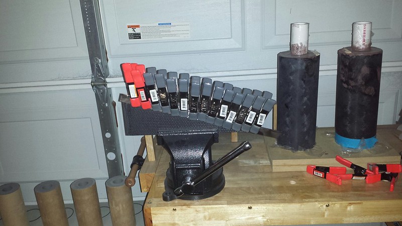
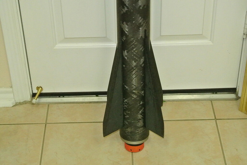
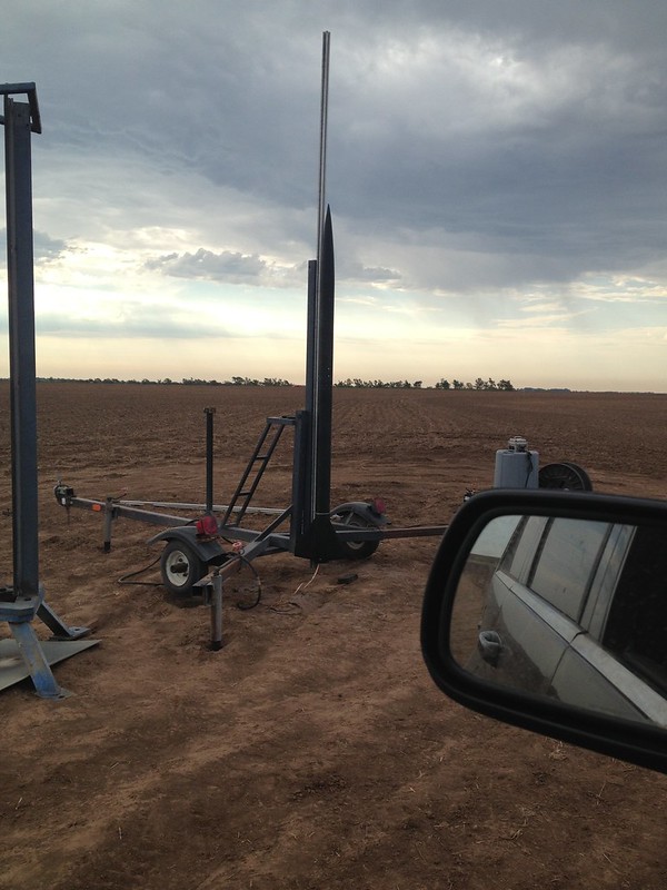
The tip-to-tip was then vacuum bagged for ~6 hours and then the rocket was loaded into a trailer and headed for Gerlach.


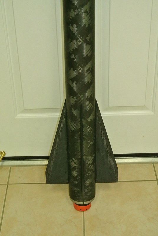
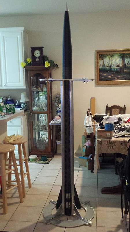
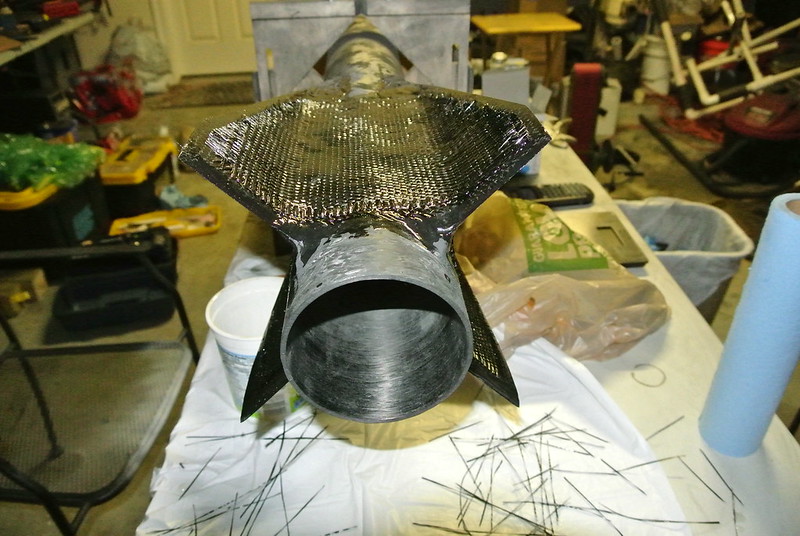
On a side note that last picture brings me to a question that I couldn't seem to quite get answered. This is a subject that I have virtually no understanding on. If you notice this is a four fin rocket so there is less space between each fin. The fillets are huge, going up the fin span ~1" and leaving ~2.5" of just fin left. The addition of 4 layers of carbon cloth further piled onto that. Basically after all said and done the fin area had a lot built up onto it (as can be seen). My question is, if this would alter the air flow across the fins and somehow reduce the fins ability to produce stability?
 
Disclaimer:
I am trying to restate this as accurately as possible. In the heat of the moment not everything was documented and some of this stuff I did was ~3 weeks ago (I am busy so memory no buneo). Take it all with a grain of salt.
 
I like this build rev better no chicken fasteners :)

I can answer your fin question I would think you gain some base drag weather or not it makes up for the removed fin area I have no idea.


Best of luck on the flight
 
Disclaimer:
I am trying to restate this as accurately as possible. In the heat of the moment not everything was documented and some of this stuff I did was ~3 weeks ago (I am busy so memory no buneo). Take it all with a grain of salt.

We all get there at one point or another- :facepalm:
Amazing build- cant wait to see vids of it flying.
 
All I got to say is, thats the spirit. You no longer going to make the trip over here to Las Cruses?


Alexander Solis

TRA - Level 1
Mariah 54 - CTI RedLightning- I-100 - 6,345 Feet
 
I like this build rev better no chicken fasteners :)

I can answer your fin question I would think you gain some base drag weather or not it makes up for the removed fin area I have no idea.


Best of luck on the flight


I suspected about the drag at the base… thanks for the response.

Haha thank you very much! I like it much better also! Give me some time and I will post all the new revisions.
 
I suspected about the drag at the base… thanks for the response.

Haha thank you very much! I like it much better also! Give me some time and I will post all the new revisions.

sorry I meant to say cant answer. I dont really have any idea.
 
Yes the airframe in reality is ~3.18mm thick and so is the nose cone. They do both have the same OD and it is a smooth transition. The nose cone shoulder (coupler) tube is even ~3.18mm thick but obviously it has a different OD (just in case it needed to be said :p).

In case you noticed, a couple of the drawings (first picture) at certain angles, makes the nose cone appear as if it has a slightly smaller OD.

Something confusing me about this. You originally said the airframe OD was 3.983 and you have 3mm thick walls which should make the ID ~3.747 which is too small to fit the motor case that CTI says is 3.875 - what am I missing?

Thanks
Zeb
 
Not sure what happened on my part but you are right. The designed dimensions were OD = 4.125", ID = 3.875", Wall = 0.125". The actual dimensions ended up being OD = 4.162", 3.903", Wall = 0.1295". Sorry for the confusion.
 

Latest posts

Back
Top