smapdiage9
Well-Known Member
- Joined
- Mar 14, 2009
- Messages
- 442
- Reaction score
- 3
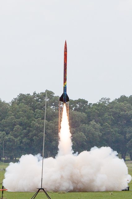
Let’s do this!
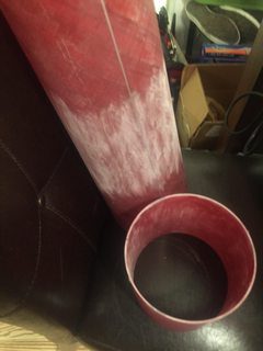
It all starts with bath time:
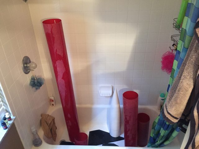
And now that it’s clean, let’s make the entire room dirty by roughing up everything with a power sander:

My harbor freight cordless oscillating tool is, once again, the best rocket building thing I have ever purchased.
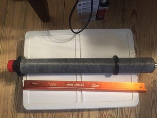
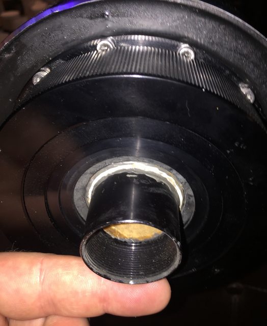
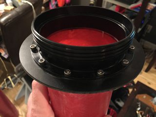
One of the first lessons I had to learn on this build is that the flanged aeropack retainer does not overlap the MMT at all. It’s on you to center it over the tube precisely and then it secures only to the aft centering ring. I don’t have any 98mm cases, but a 4” tube (or, in my case, a 3” motor with an aeropack 98 to 75 adapter shimmed with masking tape into the center of the MMT) sufficed to line things up. Once it was aligned I drilled, tapped, and installed screws one at a time. I accomplished this with the aft CR tacked into place using CA.
The balancing act here is lining up the MMT, aeropack screws, recovery bridle, and fin slots to where nothing interferes with anything else. My first interference was with the screws sticking out of the aft centering ring, and I made some space using the cutting blade on my oscillating tool which went through the screws like butter. I totally ended up not needing this at all, which goes to show you: test fit more times than you think you need to!
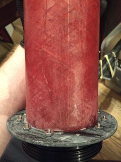
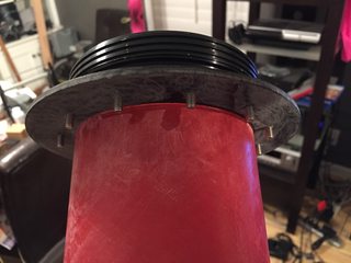
I removed and greased the screws, reinstalled them one by one backed by nuts (since the provided threaded inserts are designed for a wooden CR not a fiberglass one) and then slopped rocketpoxy all over everything. I cleaned it up a little better than this, so once it was dry I had a structural fillet between the CR and MMT, with epoxy-retained nuts acting as further thread purchase behind the thin centering ring, and all the screws are still removable meaning I could swap or replace this retainer.

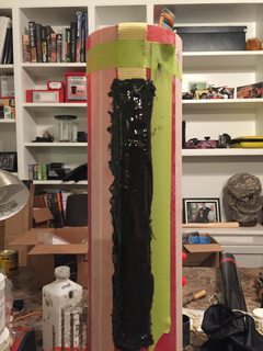
Once all the fin slot positions were traced out I blocked them off with white masking tape then slathered on another big goopy mess of rocketpoxy to retain the Kevlar bridle in the gaps.
The next piece of interference to work out is backing up the rail button screws. I positioned one above the forward CR location (so no interference with anything) and one just forward of the aft CR location. These positions meant I can take the assembled MMT with CRs and insert it diagonally to avoid needing to notch the forward CR to get past the aft tee nut. I originally bought rubber well nuts to do this but I couldn’t make them fit with the screw size I had for the 1515 buttons I had on hand, so I ended up using steel tee nuts with a fillet of epoxy retaining them in place. Greased screws once again made everything line up perfectly but still be removable.
The Kevlar bridle has to be treated carefully during assembly to avoid soaking in epoxy or suffering wear points. The only portion where it is encapsulated by epoxy are several inches down the end of the tube so pulling forces are relatively straight by the time it reaches the epoxied portion, and the rest is covered by masking tape to prevent any further glue from touching it. Two rounded notches were filed into the forward CR and sanded smooth to avoid wear points.
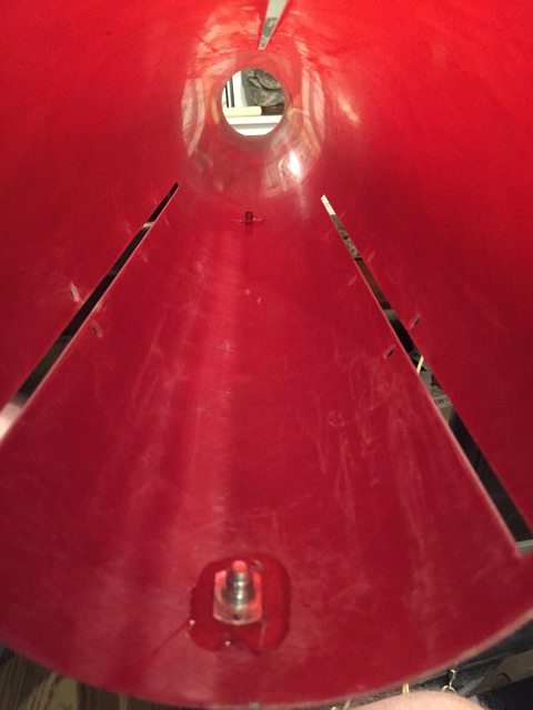
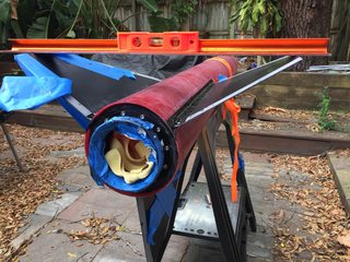
Lined up:


Alright so once that MMT was inserted in place I began tacking fins with rocketpoxy. The same method I used for my Extreme Wildman worked well here: use angle iron to make a bracket that holds the tube in place with the working fin slot exactly on the top of the tube, then secure a level to the fin and use tape to hold it in place until the tacking glue is dry. It would be a lot faster to just use a fin alignment jig but this is easy and works too.

Time for epoxy mess! I did injected internal fillets with syringes, with 10ml syringes in four evenly spaced holes along each fin root edge. Rocketpoxy mixed with chopped carbon fiber. Note for future: 10ml syringes are WAY too small, whatever size your syringes are you probably won’t be able to get it totally full which means you’ll end up filling them over and over. I did each set quickly, so that I could tilt the tube to let it flow forward and backward along the fin root and connecting to each centering ring.
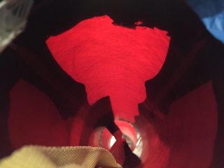
Translucent tube makes it easy to see your coverage: I used undyed rocketpoxy (white) on the fin root edge for tacking, then black rocketpoxy for the fillets so you can see the difference. The peaks are because I spaced the injection holes a little far away from the fin slot, except that large peak on the left which is actually the fin can bridle attachment point.
Once all that mess was over, it was time for the outside mess of external fillets. Alcohol covered PVC cap was used to make fillets. Note for future: fill in the injection holes before you make external fillets, so you don’t end up with four big divots that have to be filled in later.
My nosecone came with a wooden bulkhead and U-bolt. I roughed and cleaned everything up and then just slopped epoxy to secure it into the nosecone. I run my trackers inside the avionics bay, and this avbay is gigantic which means I really don’t have any need to put anything in the nose. If I want to add weight later I’ll just drill a hole and pour in an epoxy/lead slurry, there’s plenty of real estate.

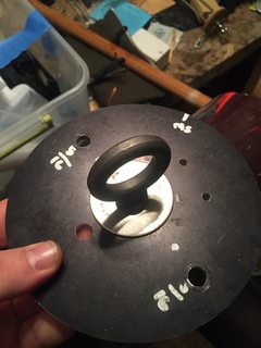
The ultimate comes with aluminum bulkheads. Everybody loves these because they are slick but I have always been annoyed by them because they’re harder to drill holes in, way heavier than fiberglass or wood, and almost impossible to sand if they don’t fit properly. For mine I made two holes for the allthread, one for the giant shouldered eye bolt, one for primary and alternate match leads to go through, two for charge holder screws, and one for the tracker antenna.
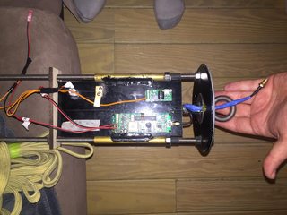
I used two schurter rotary switches to disconnect arming power for my Eggtimer TRS and Featherweight Raven 3. The image of the sled is a test fit; I fully encapsulated the brass tubes with epoxy to hold the sled in between them, then use a piece of laser cut blocking wood on either end held in place by nuts so that for/aft forces are transmitted directly through the sled/wood/nuts to the allthread.
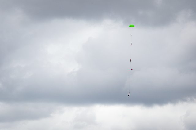
The recovery system doesn’t have any pics yet. Here’s what I’m using:
120” Top Flight main chute
24” Sky Angle Cert 3 drogue
½” tubular Kevlar throughout, except 1” flat Kevlar fin can bridle.
5/16” steel allthread and hardware
3/8”x1-1/4” machinery eye bolts
The payload tube is secured to the avionics bay/coupler with steel 4-40 screws and pem nuts epoxied inside the coupler.
The main compartment separation and drogue compartment separation are retained from early separation by 3x 4-40 nylon screws acting as shear pins. Burnout deceleration simulates to about -2.7Gs. Burnout mass of the nosecone, bulkhead, and parachute is 1497g, then adding recovery harness and wrap estimates totals 1750g times a 3G max deceleration = 5250g or 11.5lbs of decel force. Three 4-40 screws provide a shear resistance of 92-138lbs which means a minimum 8-9 times safety factor above the simulated deceleration forces to prevent premature main chute deployment. Convention has other rocket builders using their maximum acceleration as a target retention need assuming a worst-case instant stop; for this flight (M1350W) that is 9.5G, or 36.6 lbs so either way three 4-40 pins is sufficient. This is all based on conventional shortcuts since a real answer would involve the drag difference between the forward and aft portions of the rocket and their relative weights but let’s not worry about that!
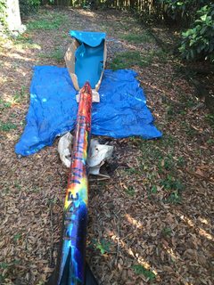
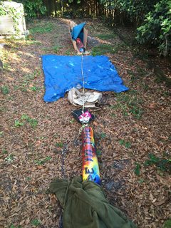
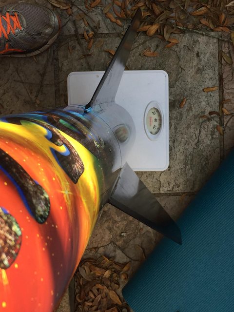
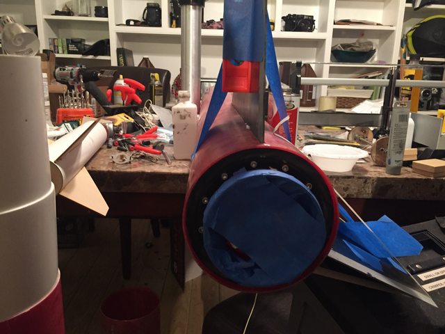
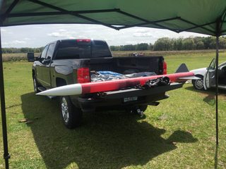
Starting to realize that this is a big damn rocket:
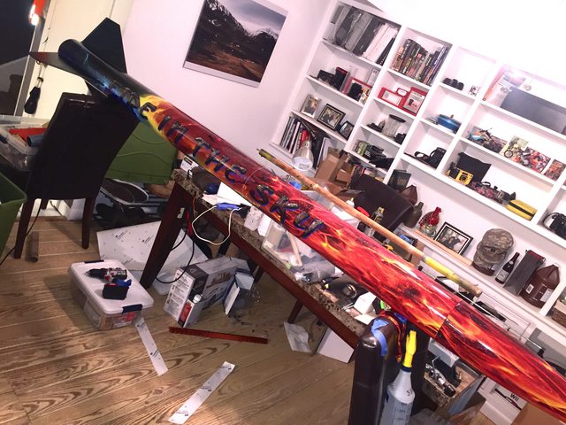
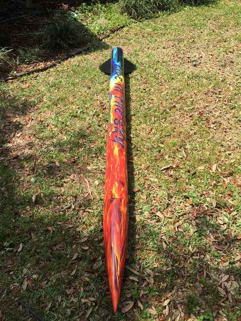
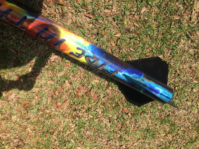
I really dislike painting and finishing. Stickershock23 came through again for me on this one: my pink fractal Extreme Wildman was my first wrap and it came out so well I knew I’d do it again on this one. I said “I want fire on the front and outer space on the back!”
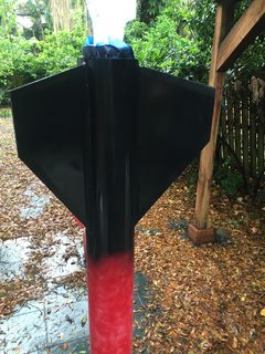
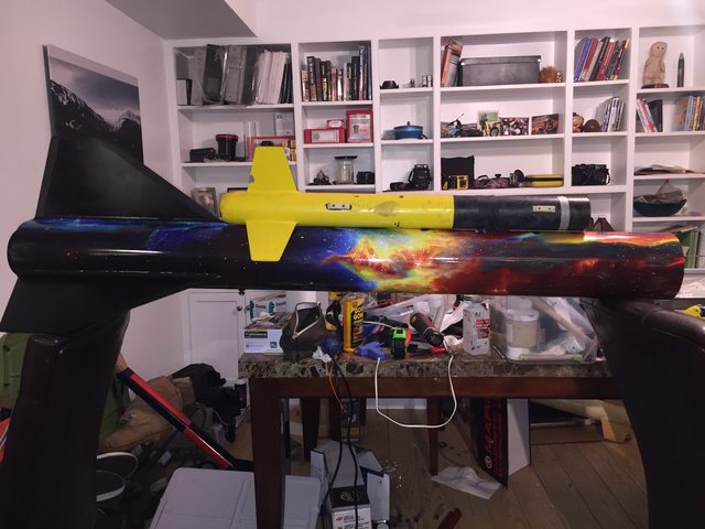
Painting the fins black:
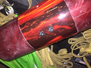
Wrapping the nosecone and payload:
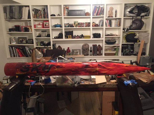
The completed wrap:
It all starts with bath time:
And now that it’s clean, let’s make the entire room dirty by roughing up everything with a power sander:
My harbor freight cordless oscillating tool is, once again, the best rocket building thing I have ever purchased.
One of the first lessons I had to learn on this build is that the flanged aeropack retainer does not overlap the MMT at all. It’s on you to center it over the tube precisely and then it secures only to the aft centering ring. I don’t have any 98mm cases, but a 4” tube (or, in my case, a 3” motor with an aeropack 98 to 75 adapter shimmed with masking tape into the center of the MMT) sufficed to line things up. Once it was aligned I drilled, tapped, and installed screws one at a time. I accomplished this with the aft CR tacked into place using CA.
The balancing act here is lining up the MMT, aeropack screws, recovery bridle, and fin slots to where nothing interferes with anything else. My first interference was with the screws sticking out of the aft centering ring, and I made some space using the cutting blade on my oscillating tool which went through the screws like butter. I totally ended up not needing this at all, which goes to show you: test fit more times than you think you need to!
I removed and greased the screws, reinstalled them one by one backed by nuts (since the provided threaded inserts are designed for a wooden CR not a fiberglass one) and then slopped rocketpoxy all over everything. I cleaned it up a little better than this, so once it was dry I had a structural fillet between the CR and MMT, with epoxy-retained nuts acting as further thread purchase behind the thin centering ring, and all the screws are still removable meaning I could swap or replace this retainer.
Once all the fin slot positions were traced out I blocked them off with white masking tape then slathered on another big goopy mess of rocketpoxy to retain the Kevlar bridle in the gaps.
The next piece of interference to work out is backing up the rail button screws. I positioned one above the forward CR location (so no interference with anything) and one just forward of the aft CR location. These positions meant I can take the assembled MMT with CRs and insert it diagonally to avoid needing to notch the forward CR to get past the aft tee nut. I originally bought rubber well nuts to do this but I couldn’t make them fit with the screw size I had for the 1515 buttons I had on hand, so I ended up using steel tee nuts with a fillet of epoxy retaining them in place. Greased screws once again made everything line up perfectly but still be removable.
The Kevlar bridle has to be treated carefully during assembly to avoid soaking in epoxy or suffering wear points. The only portion where it is encapsulated by epoxy are several inches down the end of the tube so pulling forces are relatively straight by the time it reaches the epoxied portion, and the rest is covered by masking tape to prevent any further glue from touching it. Two rounded notches were filed into the forward CR and sanded smooth to avoid wear points.
Lined up:
Alright so once that MMT was inserted in place I began tacking fins with rocketpoxy. The same method I used for my Extreme Wildman worked well here: use angle iron to make a bracket that holds the tube in place with the working fin slot exactly on the top of the tube, then secure a level to the fin and use tape to hold it in place until the tacking glue is dry. It would be a lot faster to just use a fin alignment jig but this is easy and works too.
Time for epoxy mess! I did injected internal fillets with syringes, with 10ml syringes in four evenly spaced holes along each fin root edge. Rocketpoxy mixed with chopped carbon fiber. Note for future: 10ml syringes are WAY too small, whatever size your syringes are you probably won’t be able to get it totally full which means you’ll end up filling them over and over. I did each set quickly, so that I could tilt the tube to let it flow forward and backward along the fin root and connecting to each centering ring.
Translucent tube makes it easy to see your coverage: I used undyed rocketpoxy (white) on the fin root edge for tacking, then black rocketpoxy for the fillets so you can see the difference. The peaks are because I spaced the injection holes a little far away from the fin slot, except that large peak on the left which is actually the fin can bridle attachment point.
Once all that mess was over, it was time for the outside mess of external fillets. Alcohol covered PVC cap was used to make fillets. Note for future: fill in the injection holes before you make external fillets, so you don’t end up with four big divots that have to be filled in later.
My nosecone came with a wooden bulkhead and U-bolt. I roughed and cleaned everything up and then just slopped epoxy to secure it into the nosecone. I run my trackers inside the avionics bay, and this avbay is gigantic which means I really don’t have any need to put anything in the nose. If I want to add weight later I’ll just drill a hole and pour in an epoxy/lead slurry, there’s plenty of real estate.
The ultimate comes with aluminum bulkheads. Everybody loves these because they are slick but I have always been annoyed by them because they’re harder to drill holes in, way heavier than fiberglass or wood, and almost impossible to sand if they don’t fit properly. For mine I made two holes for the allthread, one for the giant shouldered eye bolt, one for primary and alternate match leads to go through, two for charge holder screws, and one for the tracker antenna.
I used two schurter rotary switches to disconnect arming power for my Eggtimer TRS and Featherweight Raven 3. The image of the sled is a test fit; I fully encapsulated the brass tubes with epoxy to hold the sled in between them, then use a piece of laser cut blocking wood on either end held in place by nuts so that for/aft forces are transmitted directly through the sled/wood/nuts to the allthread.
The recovery system doesn’t have any pics yet. Here’s what I’m using:
120” Top Flight main chute
24” Sky Angle Cert 3 drogue
½” tubular Kevlar throughout, except 1” flat Kevlar fin can bridle.
5/16” steel allthread and hardware
3/8”x1-1/4” machinery eye bolts
The payload tube is secured to the avionics bay/coupler with steel 4-40 screws and pem nuts epoxied inside the coupler.
The main compartment separation and drogue compartment separation are retained from early separation by 3x 4-40 nylon screws acting as shear pins. Burnout deceleration simulates to about -2.7Gs. Burnout mass of the nosecone, bulkhead, and parachute is 1497g, then adding recovery harness and wrap estimates totals 1750g times a 3G max deceleration = 5250g or 11.5lbs of decel force. Three 4-40 screws provide a shear resistance of 92-138lbs which means a minimum 8-9 times safety factor above the simulated deceleration forces to prevent premature main chute deployment. Convention has other rocket builders using their maximum acceleration as a target retention need assuming a worst-case instant stop; for this flight (M1350W) that is 9.5G, or 36.6 lbs so either way three 4-40 pins is sufficient. This is all based on conventional shortcuts since a real answer would involve the drag difference between the forward and aft portions of the rocket and their relative weights but let’s not worry about that!
Starting to realize that this is a big damn rocket:
I really dislike painting and finishing. Stickershock23 came through again for me on this one: my pink fractal Extreme Wildman was my first wrap and it came out so well I knew I’d do it again on this one. I said “I want fire on the front and outer space on the back!”
Painting the fins black:
Wrapping the nosecone and payload:
The completed wrap:
Last edited:
")