amiliv
Well-Known Member
- Joined
- Jul 2, 2018
- Messages
- 124
- Reaction score
- 49
I attempted to find this online... But the pages I found either assumed non-trivial prior knowledge of the topic (too many terms and/or abbreviations I'm not familiar with) or were charts for various metals.
So, the question for somebody more fleunt in material sciences than I am, if I were to drill and tap a hole for #8-32 screw into 3/16" G10 fiberglass centering ring, what would be the approximate stripping force (i.e. how much force it can withstand before the threads in the fiberglass fail and the screw pulls out)?
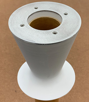
The application side for this is simple. I'll be attaching an SC Precision 4" thrust plate for 75mm motors to a 3/16" thick G10 fiberglass centering ring. The thrust plate attaches using 3 #8-32 screws, with generic instructions calling for simply tapping the holes for the screws into the aft centering ring. These screws will basically only experience the weight of the motor while the rocket sits on the pad, and the force of ejection charge trying to push the motor out at apogee. While the motor is firing, there's no force on these screws. There'd be only 3 threads (32 tpi * 3/32" = 3 threads) inside fiberglass for the screw to engage with, I'd assume this should still be plenty. But in the back of my head, I'd still like to know how much of a safety margin there is between the force of the ejection charge pushing on the motor and the force those threads in the fiberglass can withstand before failing. Would doubling aft centering ring (to have more threads engaging) be needless overkill (which I'd assume it would, but I've no data/math to back that up with).
So, the question for somebody more fleunt in material sciences than I am, if I were to drill and tap a hole for #8-32 screw into 3/16" G10 fiberglass centering ring, what would be the approximate stripping force (i.e. how much force it can withstand before the threads in the fiberglass fail and the screw pulls out)?
The application side for this is simple. I'll be attaching an SC Precision 4" thrust plate for 75mm motors to a 3/16" thick G10 fiberglass centering ring. The thrust plate attaches using 3 #8-32 screws, with generic instructions calling for simply tapping the holes for the screws into the aft centering ring. These screws will basically only experience the weight of the motor while the rocket sits on the pad, and the force of ejection charge trying to push the motor out at apogee. While the motor is firing, there's no force on these screws. There'd be only 3 threads (32 tpi * 3/32" = 3 threads) inside fiberglass for the screw to engage with, I'd assume this should still be plenty. But in the back of my head, I'd still like to know how much of a safety margin there is between the force of the ejection charge pushing on the motor and the force those threads in the fiberglass can withstand before failing. Would doubling aft centering ring (to have more threads engaging) be needless overkill (which I'd assume it would, but I've no data/math to back that up with).
")