- Joined
- Mar 27, 2013
- Messages
- 22,537
- Reaction score
- 14,965
I run my simulation and then look at the "time to apogee" then adjust my delay accordingly. Does anyone know a way of attaching external boosters? Or how about pods on the fin tips?
Pods on the fin tips? Sure my workaround is to create a body tube that is the Diameter of the tip of the fins. That body tube is .000001" thick, and .000001" long. To that, I attach launch lugs in the right places, with the correct diameter of the pod. Now If I could only figure out how to put a nose/tail cone on it. I might make the Launch lugs solid, but adjust the weight to reflect the actual values.
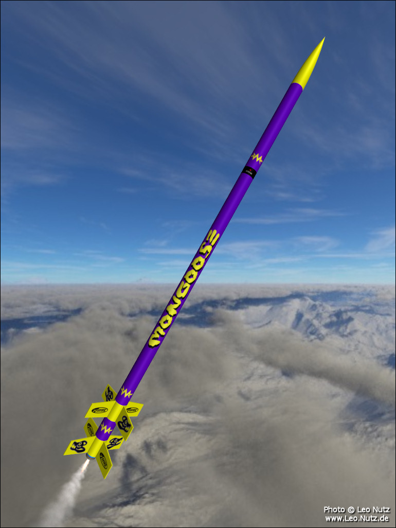
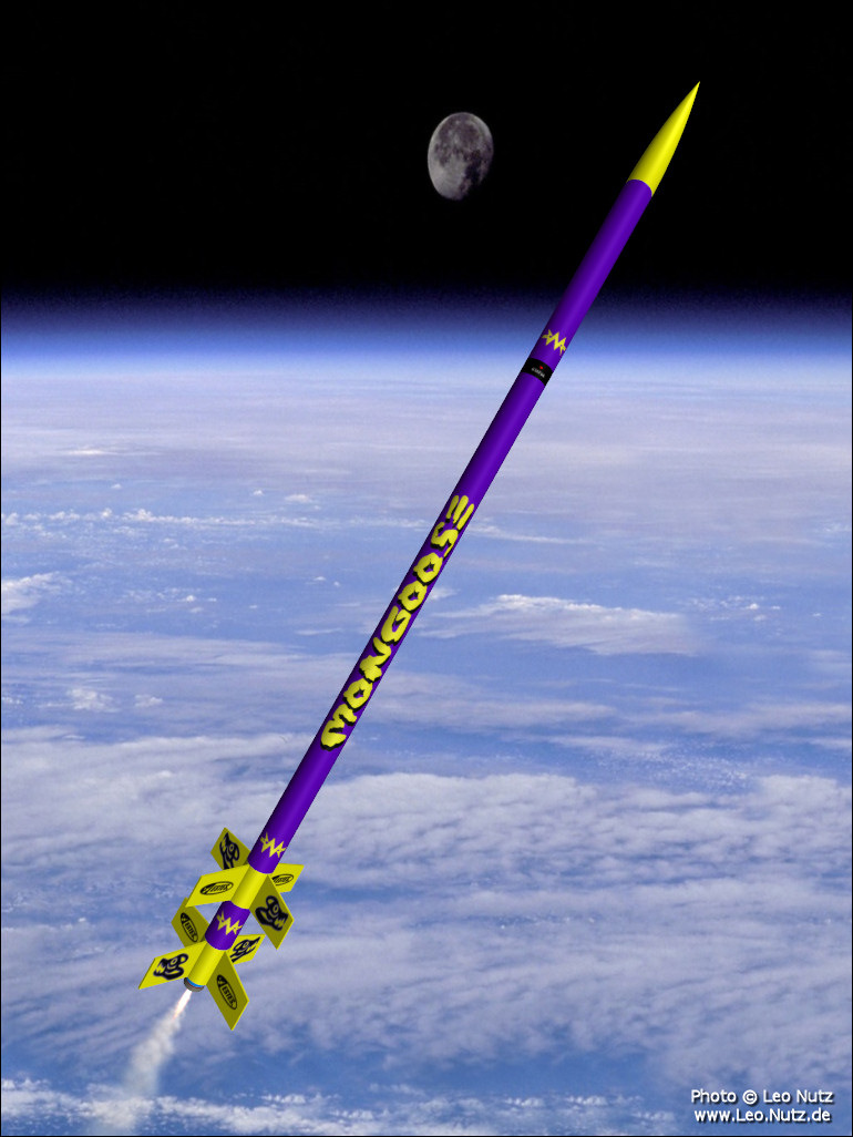
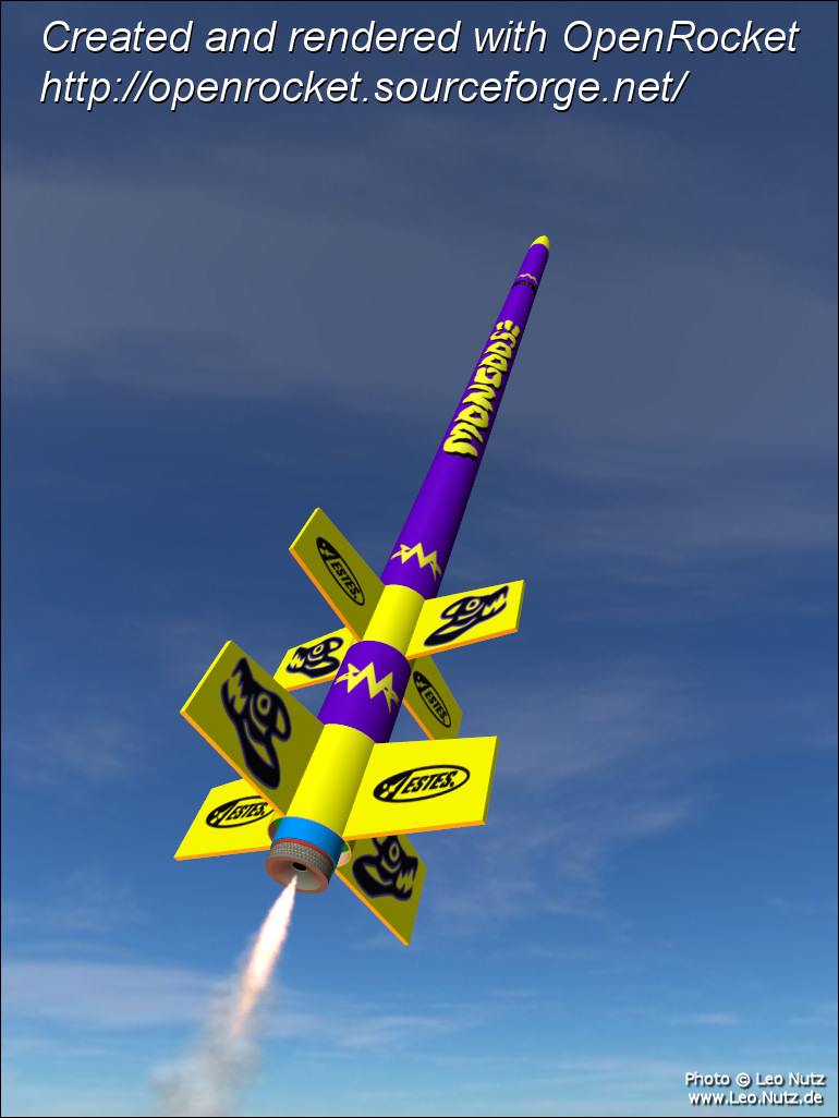
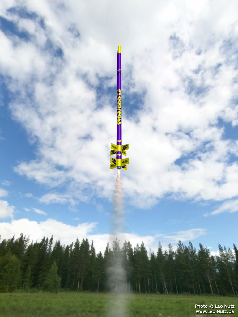
") played with the photo bit and more or less figured out how to get a skidmark motor effect...looks a little strange when you know its' a 13mm motor.
played with the photo bit and more or less figured out how to get a skidmark motor effect...looks a little strange when you know its' a 13mm motor.