- Joined
- Jan 17, 2009
- Messages
- 5,204
- Reaction score
- 1,547
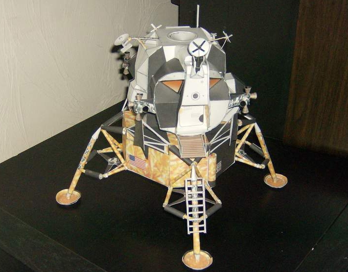
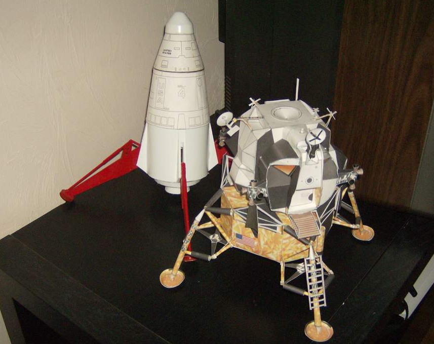
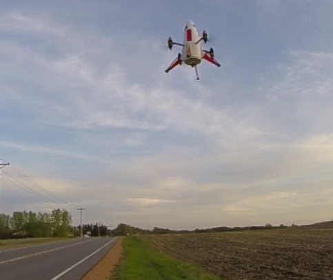
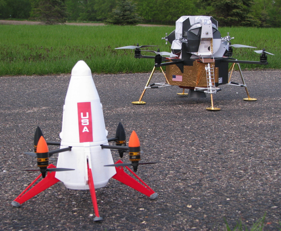
In 2016, researching more Multicopter info for my Lunar Module*, I found out that Arducopter-based Flight Controllers had a new Multicopter flight mode called “Throw Mode”. You arm the multicopter on the ground, it beeps that it is ready, pick it up, and throw it upwards into the air. When it detects it has reached apogee, it turns on the motors and stabilizes in a hover.
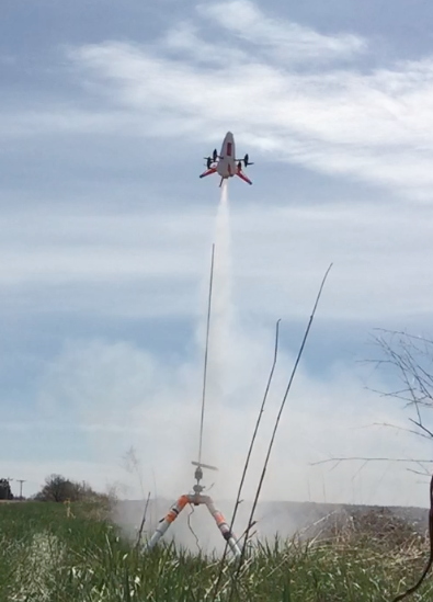
So, I got to thinking about doing a Rocket Boosted Multicopter. To take off using rocket power only, then at apogee it would automatically stabilize into a hover and then I could fly it by R/C for the rest of the flight. BTW - I have checked with experts on an Arducopter forum and they confirm it should work. I decided not to design it to fold the arms, a complication and risk factor I didn’t want to get into.
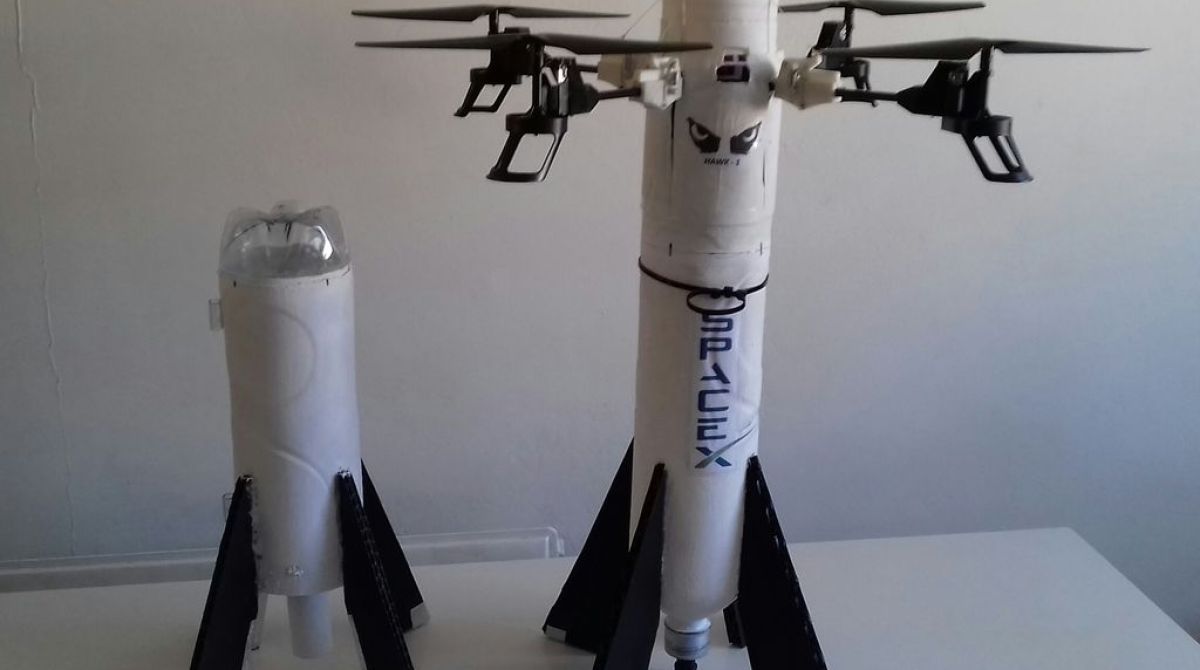
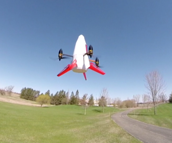
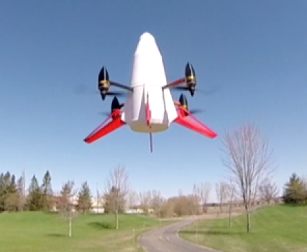
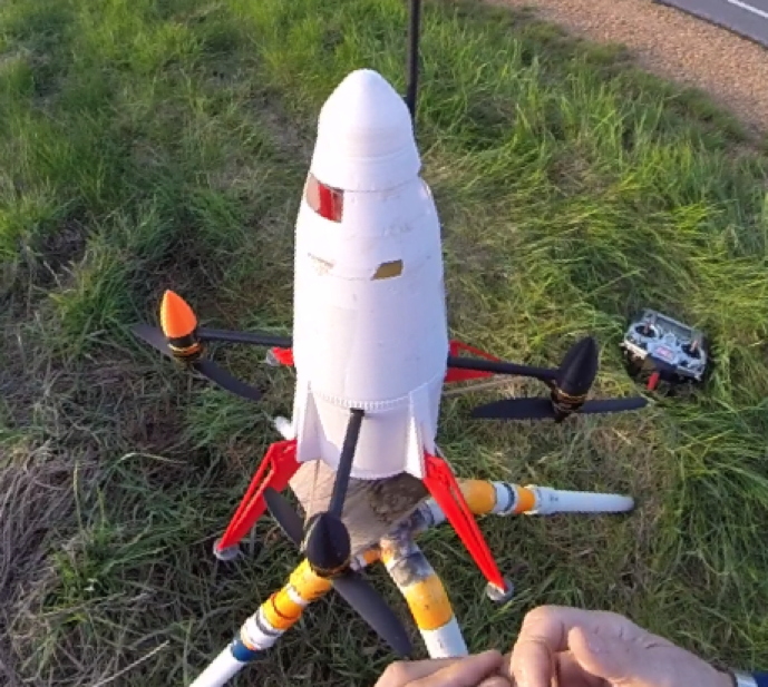
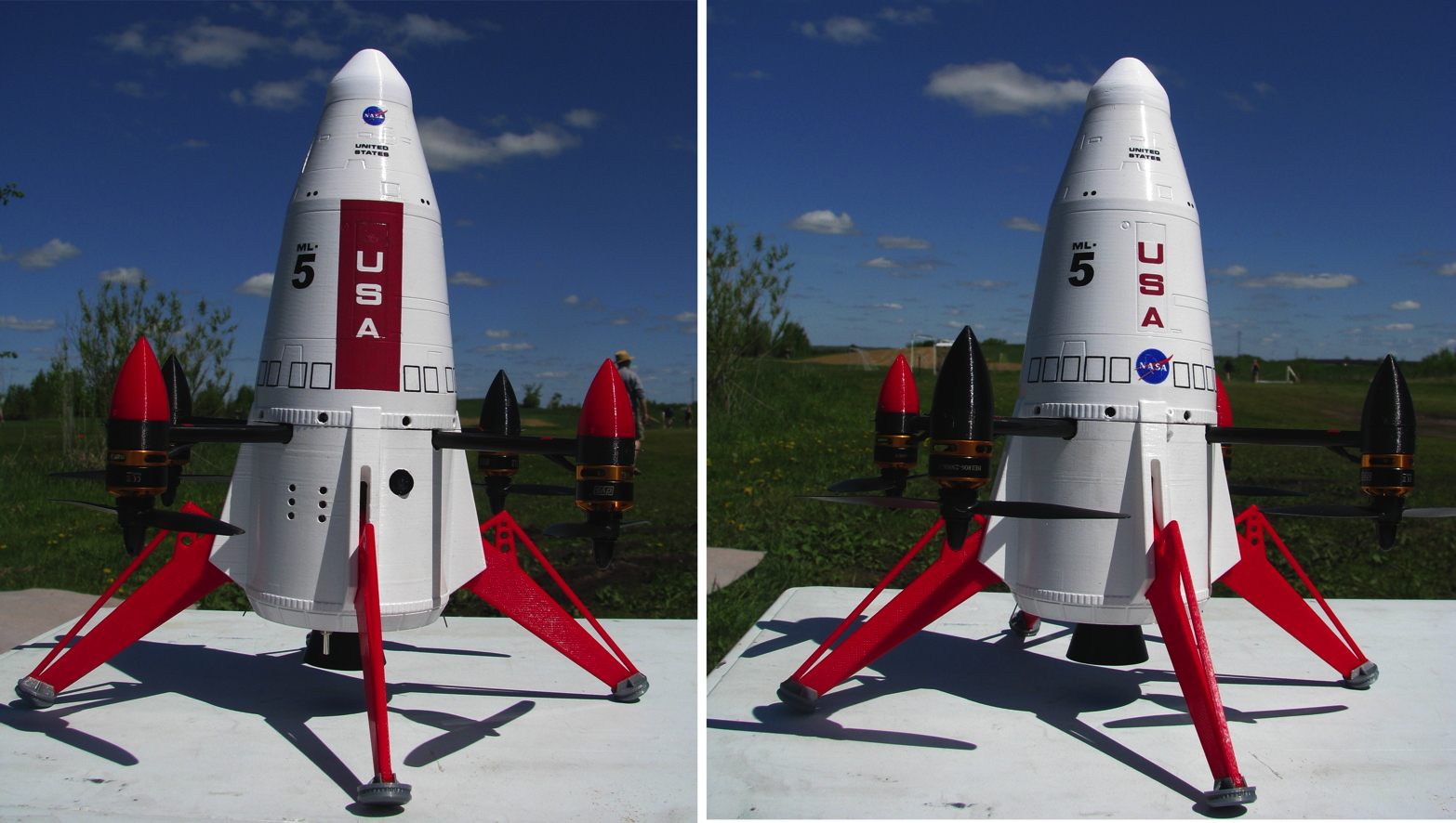
I got to thinking about other aspects of the design shape, and then hit upon a great ultimate shape for it. Far more than “just” a Rocket Boosted Quad. But I’ll save the info on the final appearance for a bit later.
I began on it in early 2017, but the project got bogged down, in large part due to the parts for the shape, and accessing those parts later. I was also in the middle of the Lunar Module Quad project, it was flying but didn’t have the covering and other things to make it look nice yet, so I shelved this project to concentrate on that. Since that time, I came across someone who could solve the shape aspect in a fantastic way, with 3D parts (I’ll mention him later). So earlier this year, I started gathering up the parts, revising the design, and collaborating with the 3D guru about the other parts.
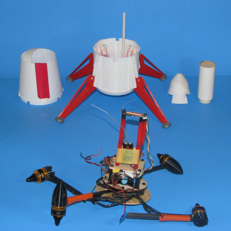
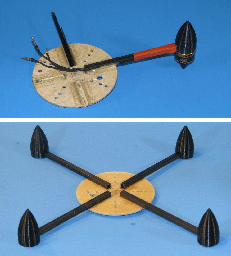
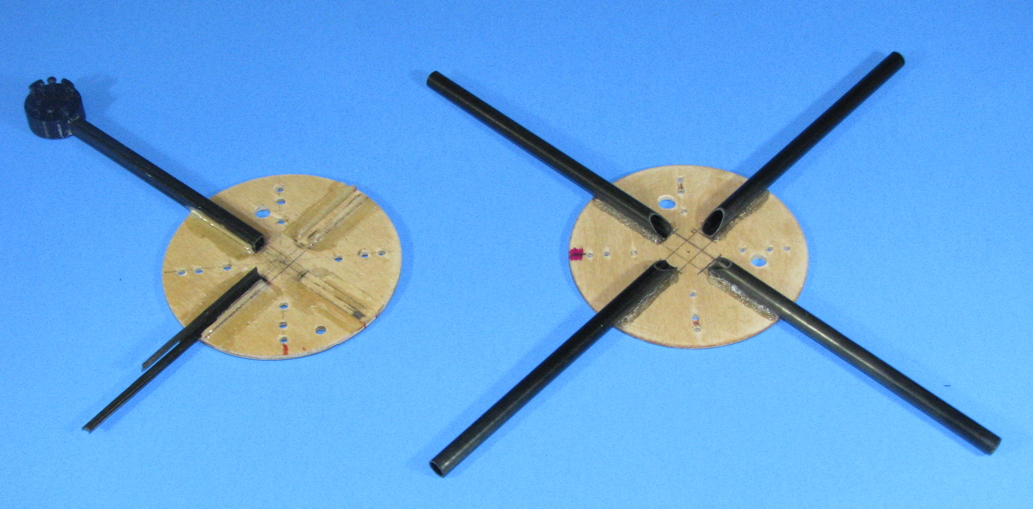
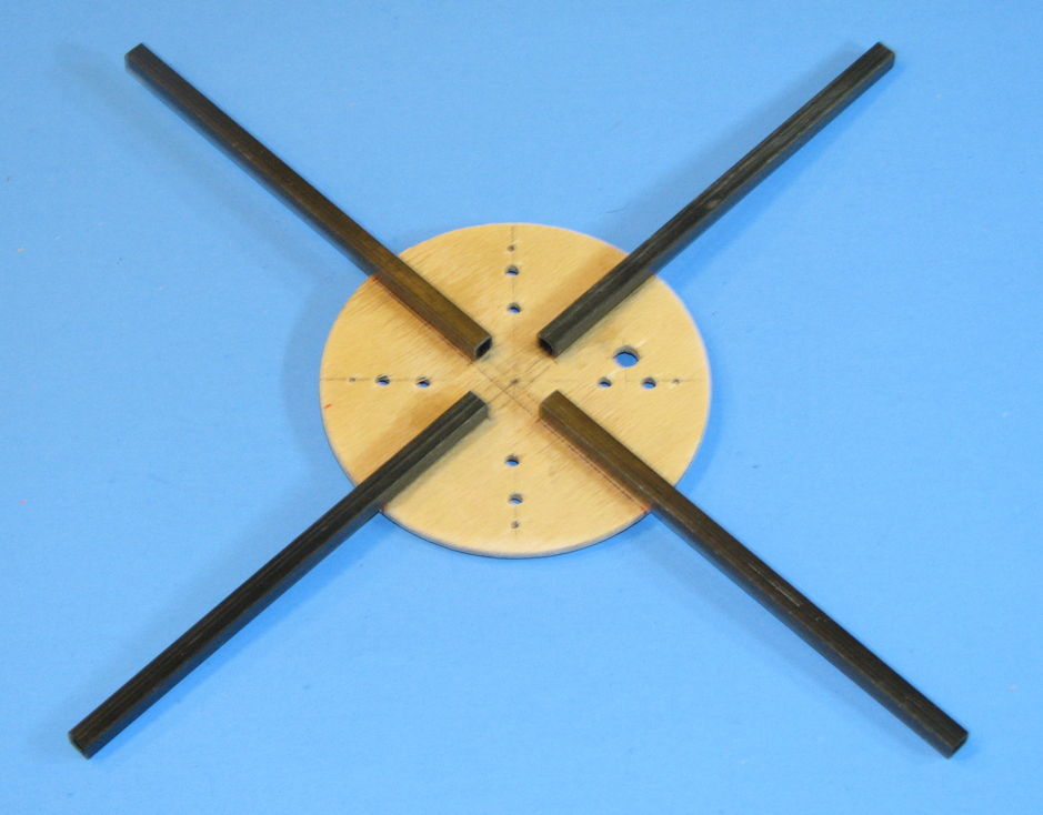
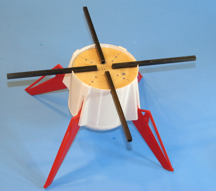
Finally started the build. The foundation is a 1/8” plywood disc to hold the graphite tube arms for the Quad motors, a “tower” assembly to hold nearly all of the electronics above it, and a rocket engine mount below it.
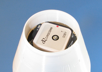
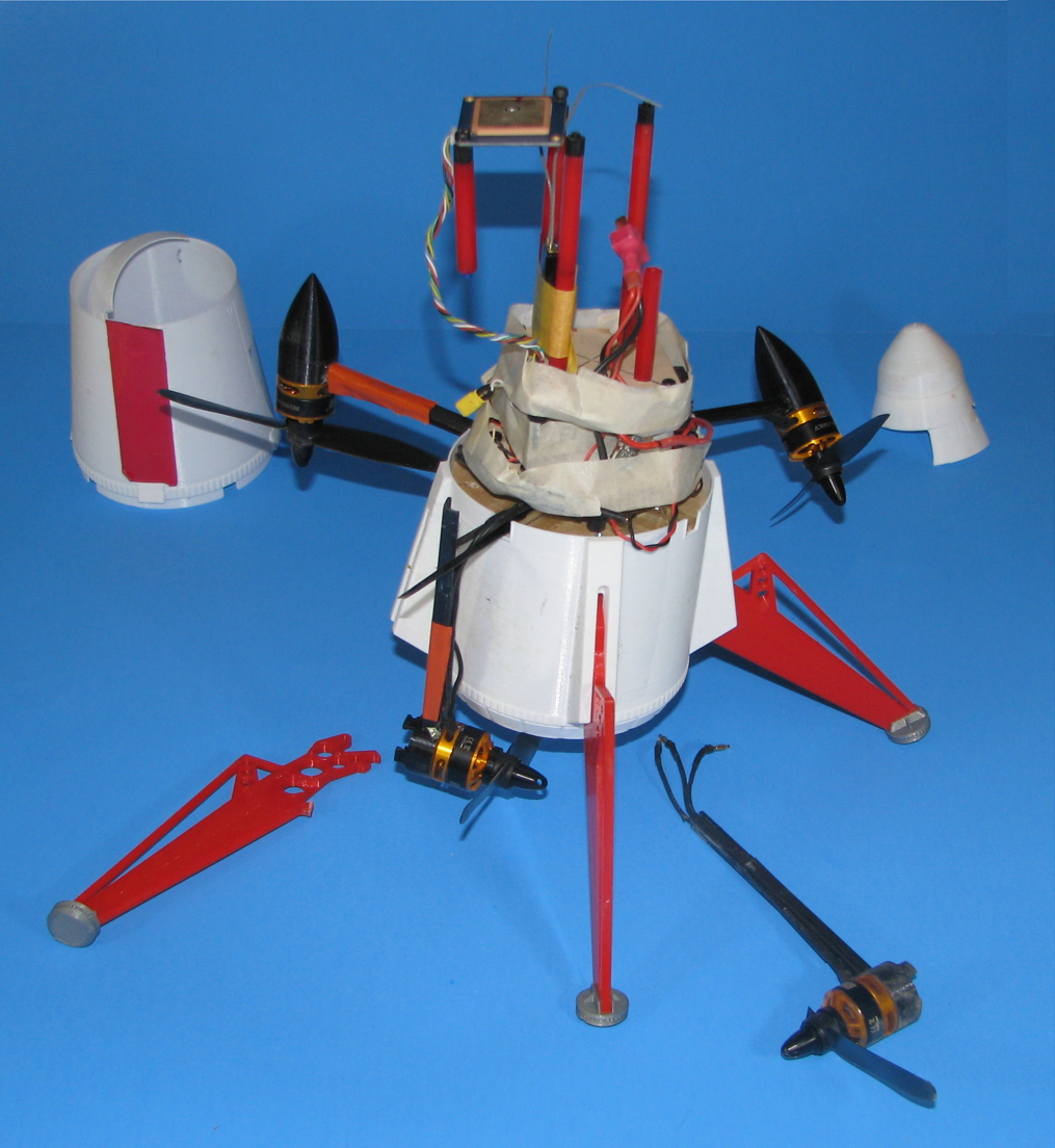
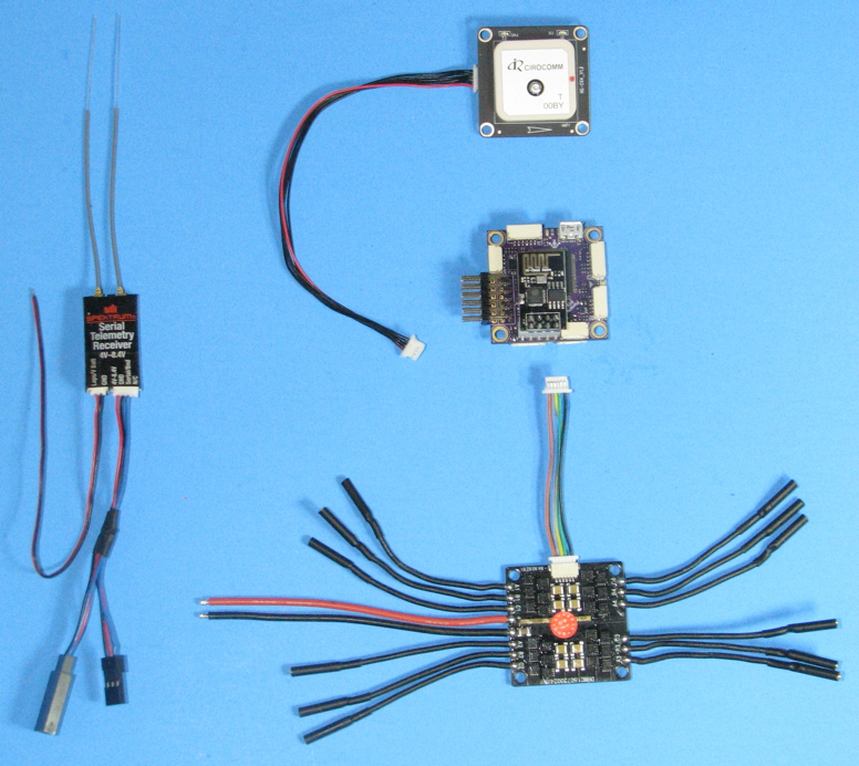
The key electronic parts needed. From top right down, a GPS receiver. “PixRacer” Flight Controller (F.C.) running Arducopter software. I would have preferred to use a "Mini-APM" F.C. as I have with other quads, but the APM's can't run the more recent Arducopter software (not enough memory), and it's the more recent software that has Throw Mode.
“Racerstar” brand 20 Amp 4-in-1 ESC (the single board controls four electric motors, 3 wires to each motor). And along the left side, Spektrum 4649 Serial receiver designed for use with Quadcopters. It uses a single bus wire to communicate to the F.C. , rather than having a separate signal wire for every channel.
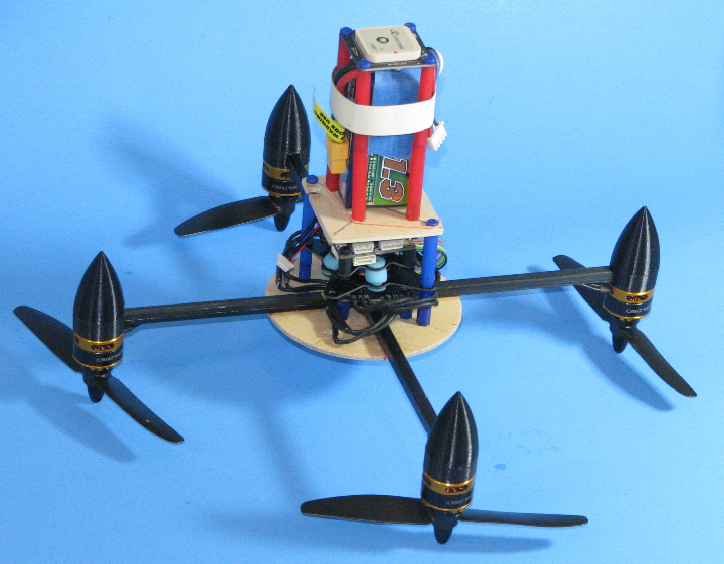
I temporarily put the tower assembly together, to check for fit, layout, and what mods to make. The tower uses a lot of 3mm nylon standoffs (blue and red parts). I do not have all the parts I need, for the lengths I want, and have an assortment on order that should arrive soon. In the pics, some legs are missing or not all secured, it'll all be redone and complete once the assortment arrives.
The 4-in-1 ESC is attached directly to the plywood disc, with short nylon standoffs. Above that, and on separate standoffs, is an anti-vibration mount to hold the Flight Controller. The light blue rubber pieces between the mount plates help to reduce vibration, allowing the F.C. to work better. The F.C. is attached to the top of the anti-vibration mount, with short black standoffs.

Above that, a 1/8” basswood ply plate, to mount the rest of the tower to hold the battery and GPS receiver.
The battery is a 1300 mAh 3S (11.1 V) Lipo. It will allow for several minutes of flying. I may also get a 600-800 mAh Lipo to reduce weight for some of the rocket boosted flights.
In the photo, the GPS receiver is right above the battery. But I’ll be adding a thin plywood disk in between, to physically protect the bottom of the GPS receiver and will add some thick aluminum tape to the disc to provide a bit of EMI shielding.
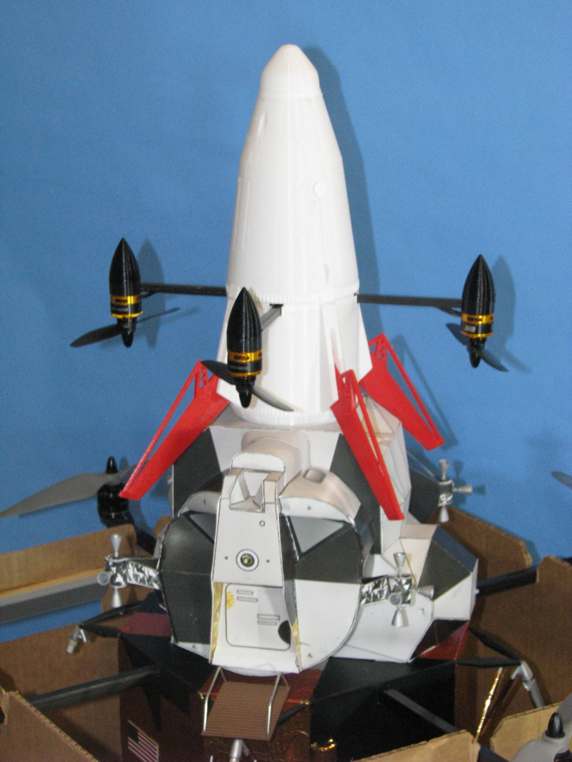
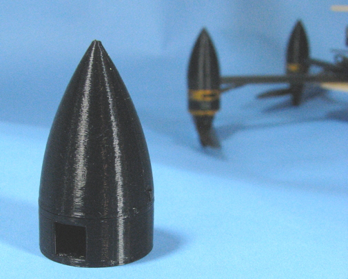
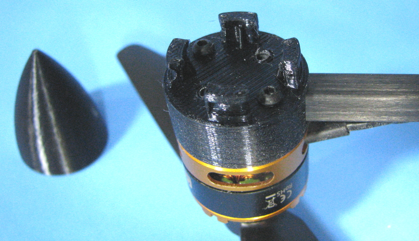
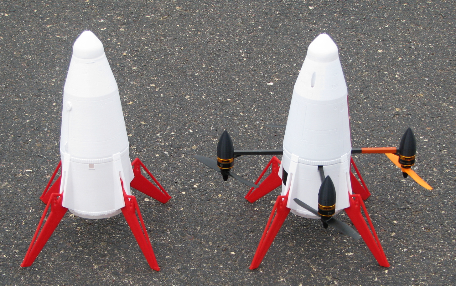
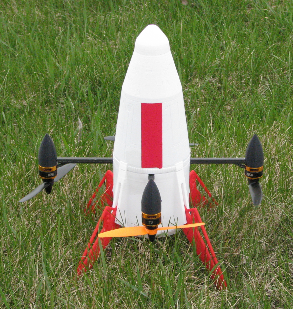
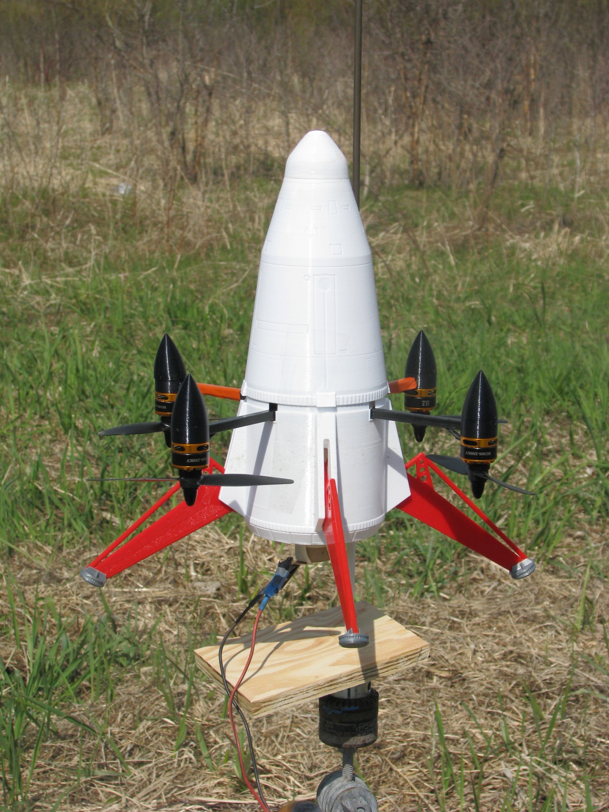
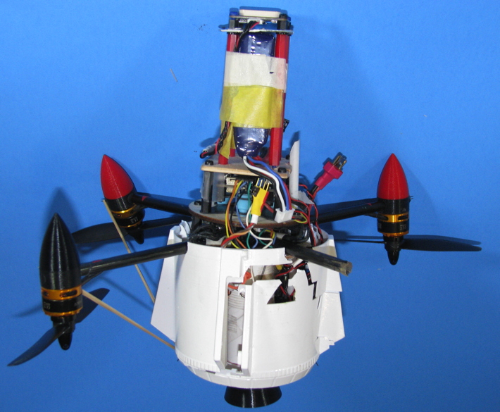
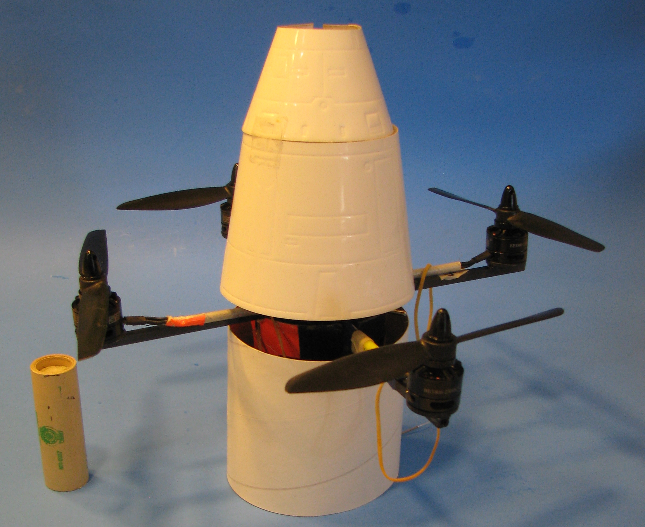
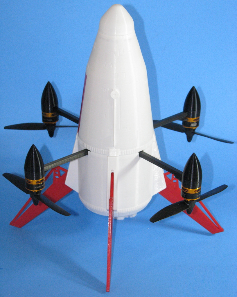
I temporarily slid the 3D printed motor mounts in place to show the basic assembly and layout of the Quadcopter. So glad that the 3D guru was willing to make those, otherwise it would be a PITA to mount to the 1/4" graphite arms. (the noses come off to allow bolt access to attach the motors).
Among the things missing in the images, are the engine mount tube underneath, receiver, assorted wiring, switch, and low voltage audio alarm.
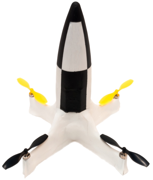
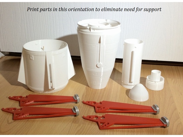
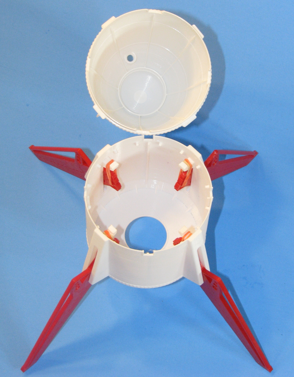
Also not shown yet, is the 3D printed shell that it will carry. And it's actually that 3D shell that transforms this project to something special. Keeping that for a surprise for a bit.
Soon, I’ll begin working with programming the Flight Controller with an Arducopter application. The old borrowed PC I had used for my other quadcopters is dead, and I’m not sure yet what I’ll use as an alternative to run the software.
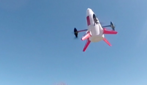
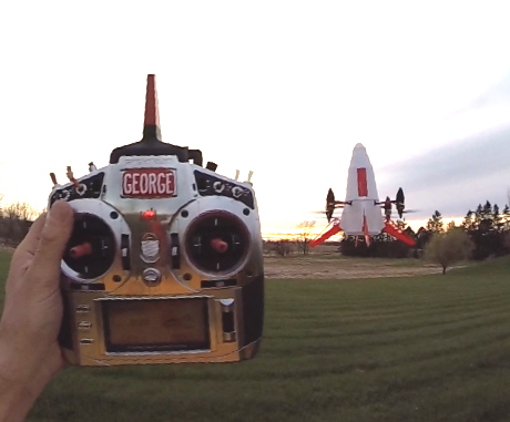
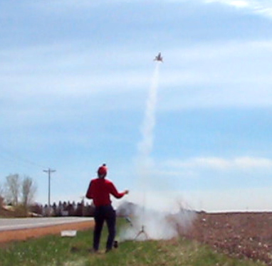
I plan to test fly this in 3 weeks or so (the big steps will be how the F.C. programming goes, and other things related to the electronics). First flights will be purely as a quadcopter. Eventually I’ll try rocket boosts. I’m torn between doing a “throw” test as in the video, and just “going for it” with a rocket boost.
* - Lunar Module Quadcopter thread: https://www.rocketryforum.com/threads/flying-r-c-lunar-module-quadcopter-project.137174/
So, I got to thinking about doing a Rocket Boosted Multicopter. To take off using rocket power only, then at apogee it would automatically stabilize into a hover and then I could fly it by R/C for the rest of the flight. BTW - I have checked with experts on an Arducopter forum and they confirm it should work. I decided not to design it to fold the arms, a complication and risk factor I didn’t want to get into.
I got to thinking about other aspects of the design shape, and then hit upon a great ultimate shape for it. Far more than “just” a Rocket Boosted Quad. But I’ll save the info on the final appearance for a bit later.
I began on it in early 2017, but the project got bogged down, in large part due to the parts for the shape, and accessing those parts later. I was also in the middle of the Lunar Module Quad project, it was flying but didn’t have the covering and other things to make it look nice yet, so I shelved this project to concentrate on that. Since that time, I came across someone who could solve the shape aspect in a fantastic way, with 3D parts (I’ll mention him later). So earlier this year, I started gathering up the parts, revising the design, and collaborating with the 3D guru about the other parts.
Finally started the build. The foundation is a 1/8” plywood disc to hold the graphite tube arms for the Quad motors, a “tower” assembly to hold nearly all of the electronics above it, and a rocket engine mount below it.
The key electronic parts needed. From top right down, a GPS receiver. “PixRacer” Flight Controller (F.C.) running Arducopter software. I would have preferred to use a "Mini-APM" F.C. as I have with other quads, but the APM's can't run the more recent Arducopter software (not enough memory), and it's the more recent software that has Throw Mode.
“Racerstar” brand 20 Amp 4-in-1 ESC (the single board controls four electric motors, 3 wires to each motor). And along the left side, Spektrum 4649 Serial receiver designed for use with Quadcopters. It uses a single bus wire to communicate to the F.C. , rather than having a separate signal wire for every channel.
I temporarily put the tower assembly together, to check for fit, layout, and what mods to make. The tower uses a lot of 3mm nylon standoffs (blue and red parts). I do not have all the parts I need, for the lengths I want, and have an assortment on order that should arrive soon. In the pics, some legs are missing or not all secured, it'll all be redone and complete once the assortment arrives.
The 4-in-1 ESC is attached directly to the plywood disc, with short nylon standoffs. Above that, and on separate standoffs, is an anti-vibration mount to hold the Flight Controller. The light blue rubber pieces between the mount plates help to reduce vibration, allowing the F.C. to work better. The F.C. is attached to the top of the anti-vibration mount, with short black standoffs.
Above that, a 1/8” basswood ply plate, to mount the rest of the tower to hold the battery and GPS receiver.
The battery is a 1300 mAh 3S (11.1 V) Lipo. It will allow for several minutes of flying. I may also get a 600-800 mAh Lipo to reduce weight for some of the rocket boosted flights.
In the photo, the GPS receiver is right above the battery. But I’ll be adding a thin plywood disk in between, to physically protect the bottom of the GPS receiver and will add some thick aluminum tape to the disc to provide a bit of EMI shielding.
I temporarily slid the 3D printed motor mounts in place to show the basic assembly and layout of the Quadcopter. So glad that the 3D guru was willing to make those, otherwise it would be a PITA to mount to the 1/4" graphite arms. (the noses come off to allow bolt access to attach the motors).
Among the things missing in the images, are the engine mount tube underneath, receiver, assorted wiring, switch, and low voltage audio alarm.
Also not shown yet, is the 3D printed shell that it will carry. And it's actually that 3D shell that transforms this project to something special. Keeping that for a surprise for a bit.
Soon, I’ll begin working with programming the Flight Controller with an Arducopter application. The old borrowed PC I had used for my other quadcopters is dead, and I’m not sure yet what I’ll use as an alternative to run the software.
I plan to test fly this in 3 weeks or so (the big steps will be how the F.C. programming goes, and other things related to the electronics). First flights will be purely as a quadcopter. Eventually I’ll try rocket boosts. I’m torn between doing a “throw” test as in the video, and just “going for it” with a rocket boost.
* - Lunar Module Quadcopter thread: https://www.rocketryforum.com/threads/flying-r-c-lunar-module-quadcopter-project.137174/
Last edited:

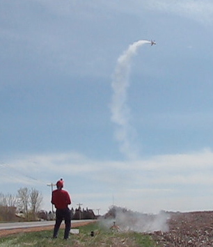
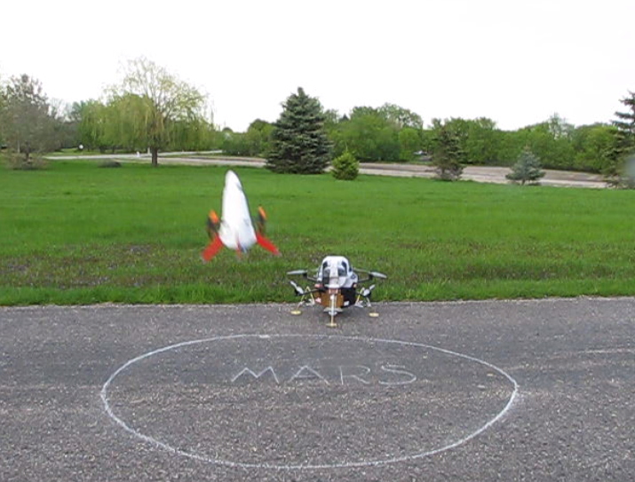
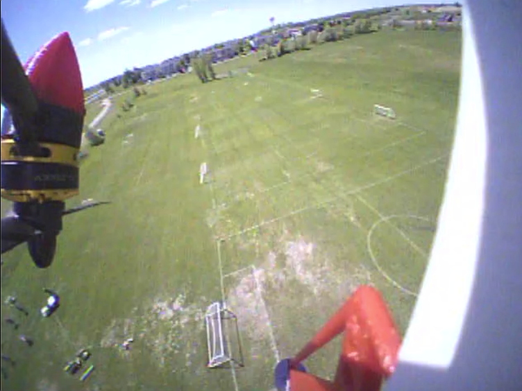
") ). There is a good chance that it may veer to one side if all four motors and props do not “windmill” the same (they are free to rotate in the airflow like a pinwheel). If one motor/prop rotated at a different rotation rate than the other three, it would cause a drag imbalance. If it becomes a problem, I have an idea for addressing it, clear spin tabs on the legs which would make it roll on boost to even things out (spiraling ballistic boost), but not have a significant effect for Quadcopter flight control. In case it veers off horribly at liftoff, and got horizontal under thrust…… the Throw Mode software SHOULD activate to stabilize it into a hover as soon as it begins to lose altitude.
). There is a good chance that it may veer to one side if all four motors and props do not “windmill” the same (they are free to rotate in the airflow like a pinwheel). If one motor/prop rotated at a different rotation rate than the other three, it would cause a drag imbalance. If it becomes a problem, I have an idea for addressing it, clear spin tabs on the legs which would make it roll on boost to even things out (spiraling ballistic boost), but not have a significant effect for Quadcopter flight control. In case it veers off horribly at liftoff, and got horizontal under thrust…… the Throw Mode software SHOULD activate to stabilize it into a hover as soon as it begins to lose altitude.