lcorinth
Well-Known Member
- Joined
- Aug 5, 2014
- Messages
- 1,022
- Reaction score
- 46
I'm interested in building my own launch pads and launch controllers. I'll soon be building a rocket that takes an E motor, and it seems that with each larger motor size (if you just go the Estes route and buy all your ground support stuff), you need to get a new launch pad and a new controller. I've looked at a few homemade controllers online, so I know you can build your own. I'm wondering if it's possible to make a controller, and also a pad, that accommodates multiple sized motors and rockets.
Mind, I'm still talking about LPR, so I'm not at a stage yet where I need to worry about rails or anything.
I've done some Googling, and have found various plans for controllers (and pads), and I could just build one of those. But I'm not entirely sure about the basics - how they function, why they need to be wired the way they do, etc.
I'd like to build a controller that will still work for a standard A-C engine, but will also function for larger ones, like D-E sized motors. I'd also like the same controller to work for cluster engines, so I can use the same controller for my first (simple, 2-motor kit) cluster launch rocket. I'm not sure if these wishes are all possible in one controller (I can still use my Estes controller for the standards, of course). I've never worked with electronics before, but I want to learn how this works. Here's what I think I know:
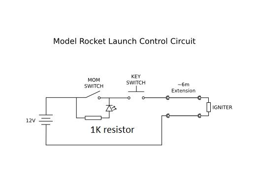
I'd like the controller to work on internal power if possible. I know some controllers use series of AA or C batteries. The Estes controller I got with my first kit uses one 9V. I was thinking of one of those lantern batteries with the spring attachments on top, but I think those are 6V, and I don't know if that's enough voltage. I would be willing to use one of those external, rechargeable (motorcycle?) batteries, but I don't want to have to rig the thing to my car. Where I fly, parking is a minimum of 600 feet from the launch site.
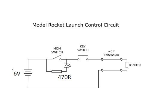
I've looked at switches and stuff at Radioshack. What I'm picturing is a small (possibly wooden) box with a battery preferably inside, with a toggle switch to arm, an LED to indicate continuity, and a momentary button switch to launch (with of course the wires - about 30-45 feet - coming out the front). I'm also not sure how to mount these things onto the casing, so I don't know if I can use a wooden box, or if I need something thinner. I don't know if I need some kind of circuit board, or if I can keep it simpler. I don't know if a launcher for a higher power motor will be too much for a standard A-C motor. If that's the case, and I want to get fancy, perhaps I can put in a switch and have two different batteries in the thing, one for higher power stuff, one for the standards. I also don't know how to wire a continuity indicator so it doesn't send all the juice to the launch pad when I simply arm the launch controller - I assume it's some sort of resistor, but I don't know how much resistance I need for what kind of battery.
I'd hasten to add that I'm not in a hurry to do this project, so please don't worry that I'm getting ahead of myself here. But I'd like to begin understanding how I can design this thing - I'd like to design it myself rather than simply copy someone else's, so that I actually understand what I'm making, and can design another one for another use if I need to or want to.
So, what are the basics I need to know about doing something like this? Feel free to be as detailed as possible, but bear in mind that I'm an electronics beginner.
(I was also going to make this thread about launch pads, but this is getting pretty long, so I'll save that for another post).
Mind, I'm still talking about LPR, so I'm not at a stage yet where I need to worry about rails or anything.
I've done some Googling, and have found various plans for controllers (and pads), and I could just build one of those. But I'm not entirely sure about the basics - how they function, why they need to be wired the way they do, etc.
I'd like to build a controller that will still work for a standard A-C engine, but will also function for larger ones, like D-E sized motors. I'd also like the same controller to work for cluster engines, so I can use the same controller for my first (simple, 2-motor kit) cluster launch rocket. I'm not sure if these wishes are all possible in one controller (I can still use my Estes controller for the standards, of course). I've never worked with electronics before, but I want to learn how this works. Here's what I think I know:
- You need enough voltage to get the igniter to fire (though I don't know how much voltage that is)
- You need enough amperes to push enough current through the length of wire to the igniter (so, if you have 30 feet of wire instead of 15, you need more amps to get it there). I think this is accomplished through a series of batteries, or a stronger battery perhaps (?)
- You need a weak enough current to run through the igniter to power the continuity light on the controller, but not so much you accidentally launch the rocket
- For cluster launches, you need to wire all igniters in parallel, not in series, with the use of a "clip whip."
I'd like the controller to work on internal power if possible. I know some controllers use series of AA or C batteries. The Estes controller I got with my first kit uses one 9V. I was thinking of one of those lantern batteries with the spring attachments on top, but I think those are 6V, and I don't know if that's enough voltage. I would be willing to use one of those external, rechargeable (motorcycle?) batteries, but I don't want to have to rig the thing to my car. Where I fly, parking is a minimum of 600 feet from the launch site.
I've looked at switches and stuff at Radioshack. What I'm picturing is a small (possibly wooden) box with a battery preferably inside, with a toggle switch to arm, an LED to indicate continuity, and a momentary button switch to launch (with of course the wires - about 30-45 feet - coming out the front). I'm also not sure how to mount these things onto the casing, so I don't know if I can use a wooden box, or if I need something thinner. I don't know if I need some kind of circuit board, or if I can keep it simpler. I don't know if a launcher for a higher power motor will be too much for a standard A-C motor. If that's the case, and I want to get fancy, perhaps I can put in a switch and have two different batteries in the thing, one for higher power stuff, one for the standards. I also don't know how to wire a continuity indicator so it doesn't send all the juice to the launch pad when I simply arm the launch controller - I assume it's some sort of resistor, but I don't know how much resistance I need for what kind of battery.
I'd hasten to add that I'm not in a hurry to do this project, so please don't worry that I'm getting ahead of myself here. But I'd like to begin understanding how I can design this thing - I'd like to design it myself rather than simply copy someone else's, so that I actually understand what I'm making, and can design another one for another use if I need to or want to.
So, what are the basics I need to know about doing something like this? Feel free to be as detailed as possible, but bear in mind that I'm an electronics beginner.
(I was also going to make this thread about launch pads, but this is getting pretty long, so I'll save that for another post).