


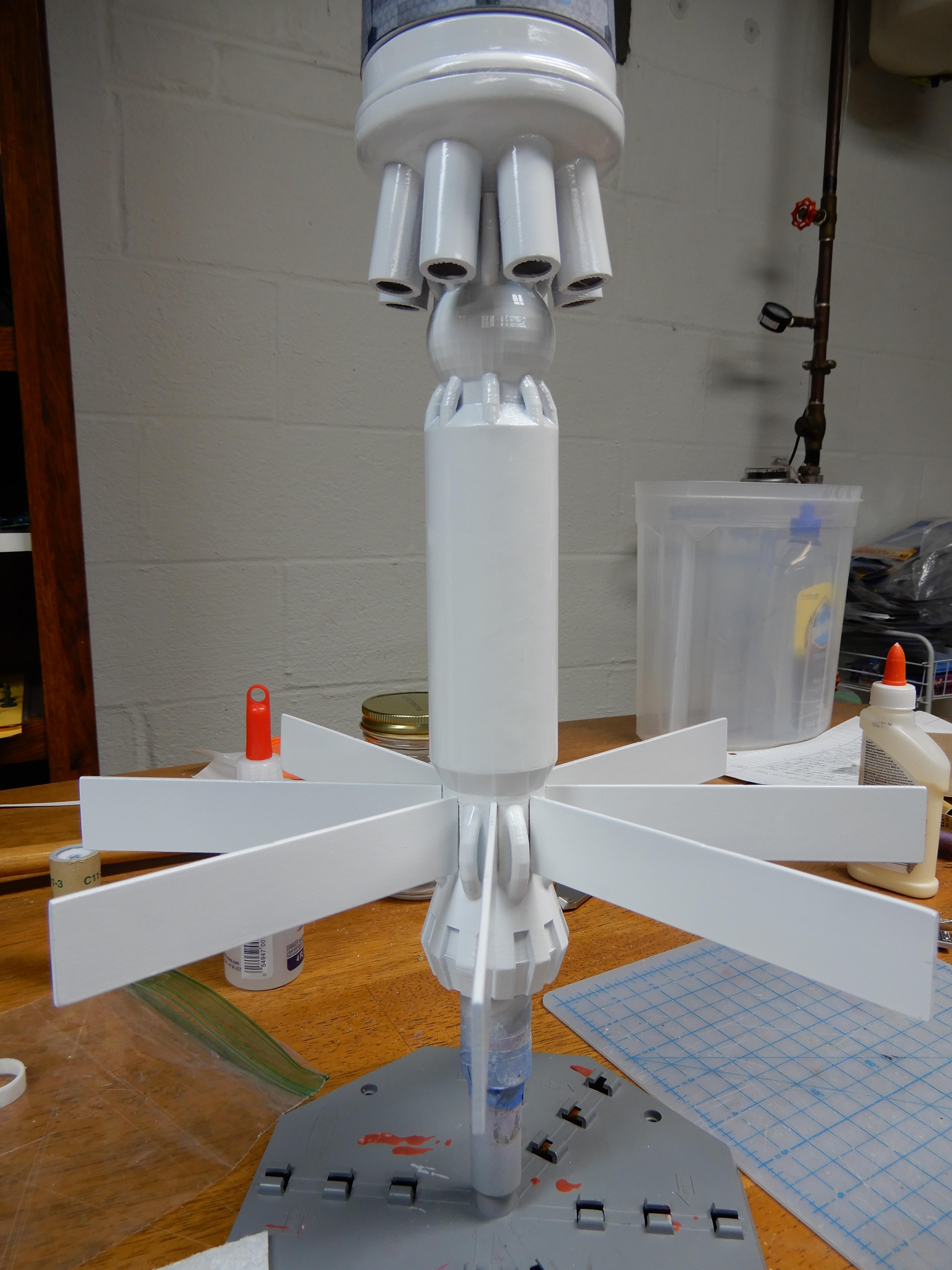
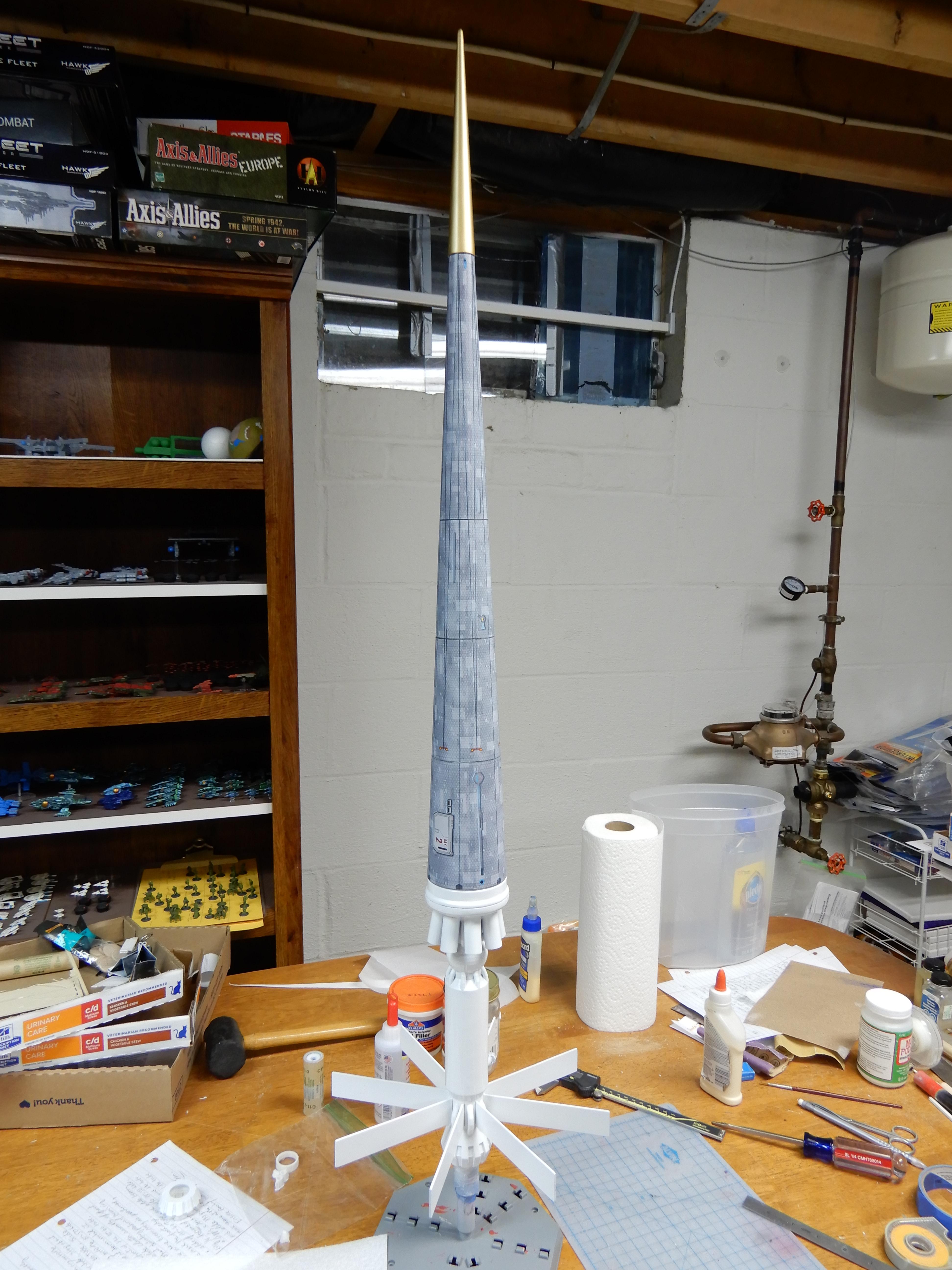
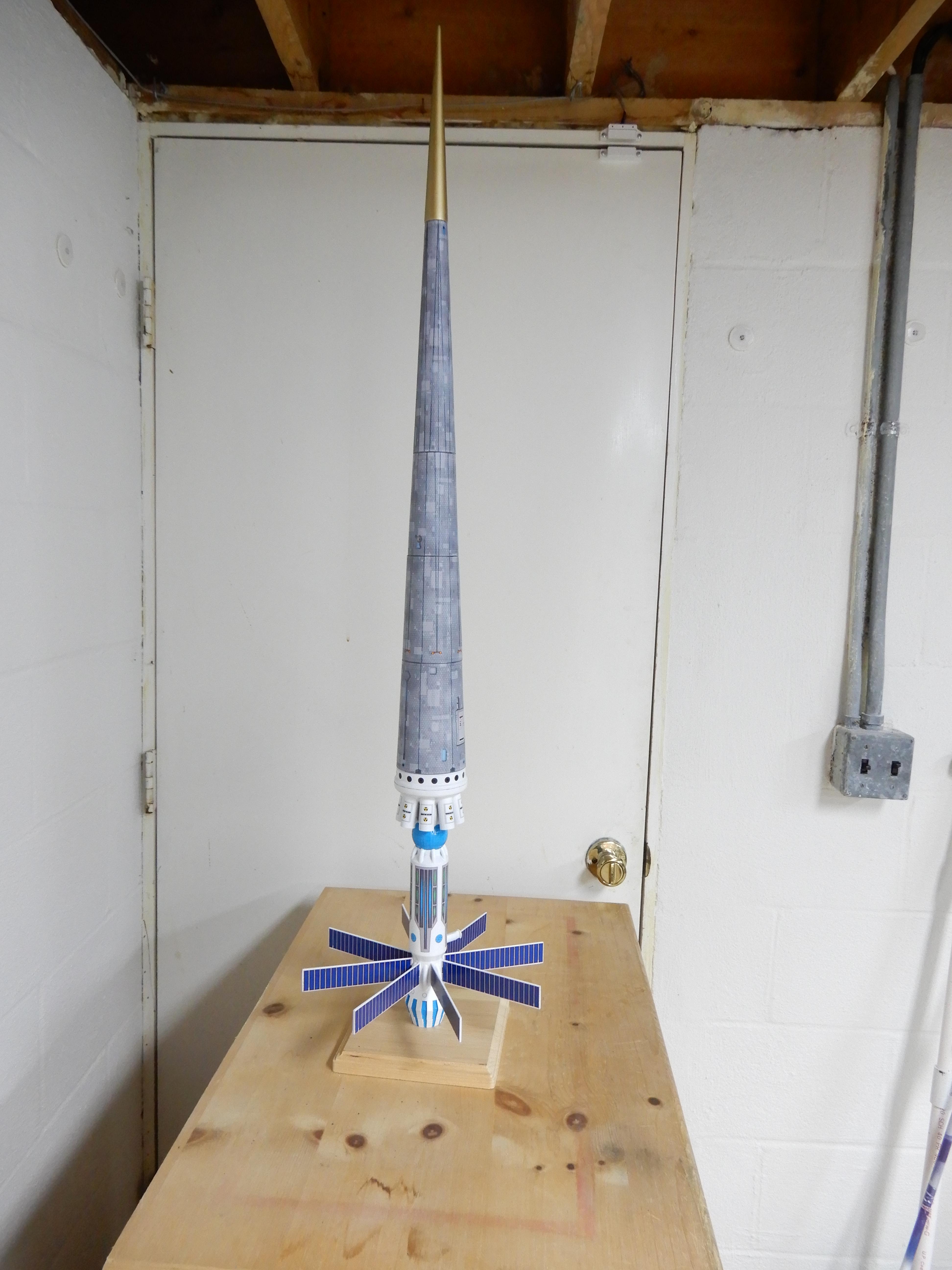
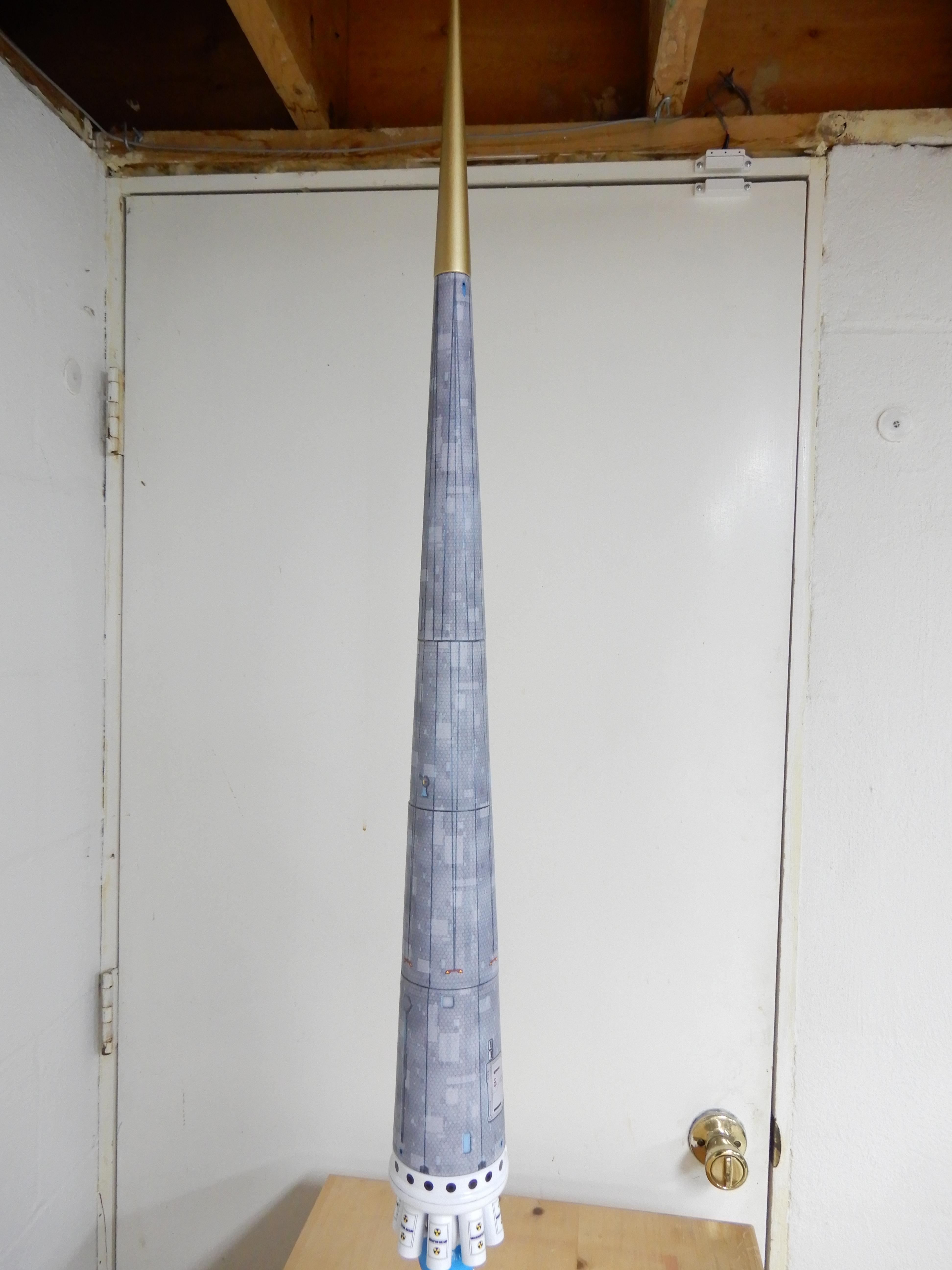
I've started construction of one of Radical Rocketry's Tau Zero Christine, with 3d printed parts by our very own BigMacDaddy. After reviewing the directions, I decided that I needed to sit down and try-fit everything and see if the results matched up with the directions. This is the result...
Pre-construction, I sanded most of the 3d printed ABS parts smooth; I decided I didn't want to mess with the using ABS bits and acetone to smooth everything.
In addition to what was provided in the builders kit, I also needed 3 x Estes green centering rings (BT-50 to 55), and an 24mm engine block.
One also needs the following body tubes:
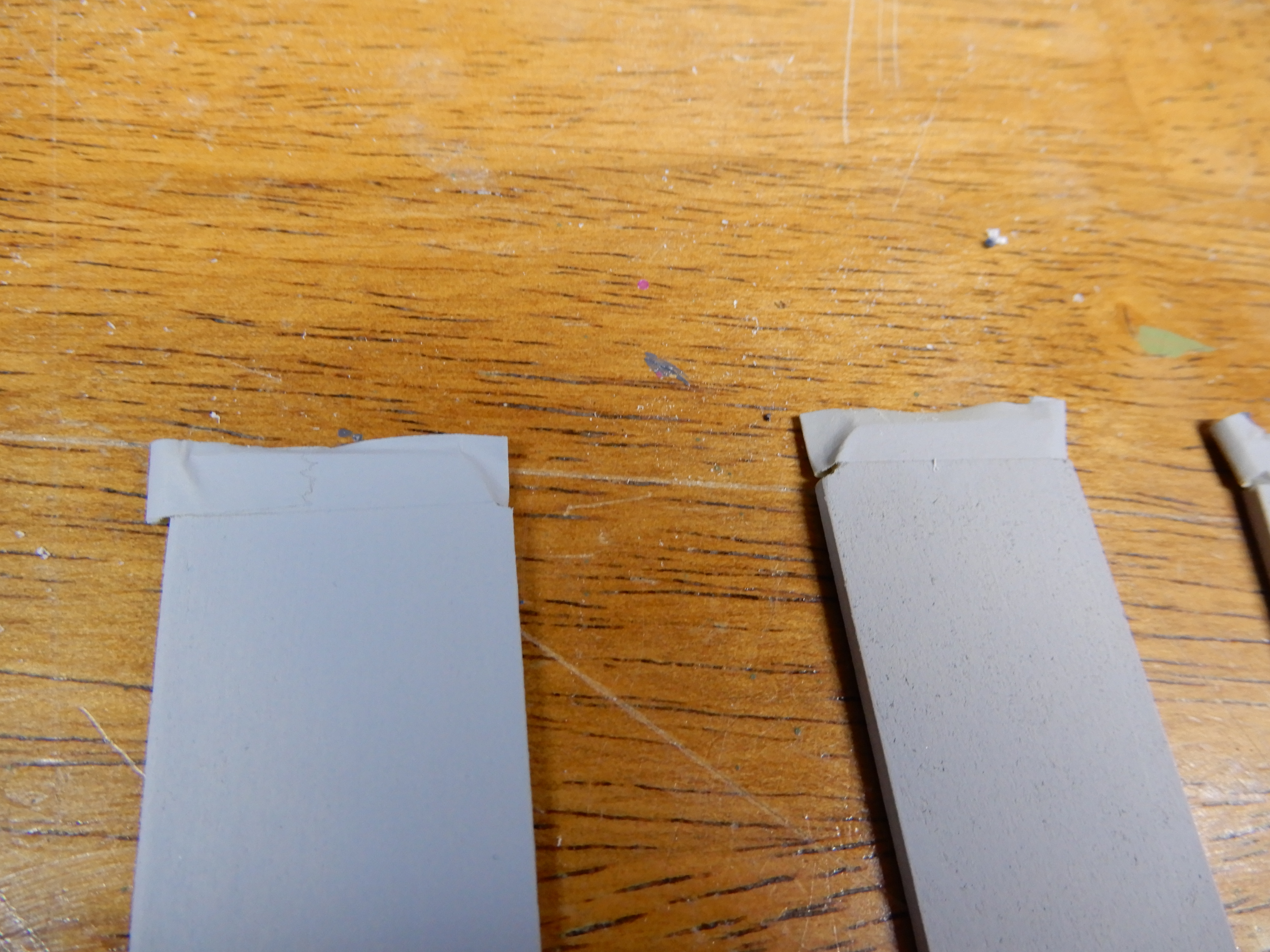
BT-20 approx 9 7/16" long, BT-50 approx 11 7/8" long, BT-55 approx 12 1/4" long (leave a little extra (1/2"? ) on the length for reasons that will become apparent later), and BT-60 4" long. Sand all of the tubes to remove the glassine.
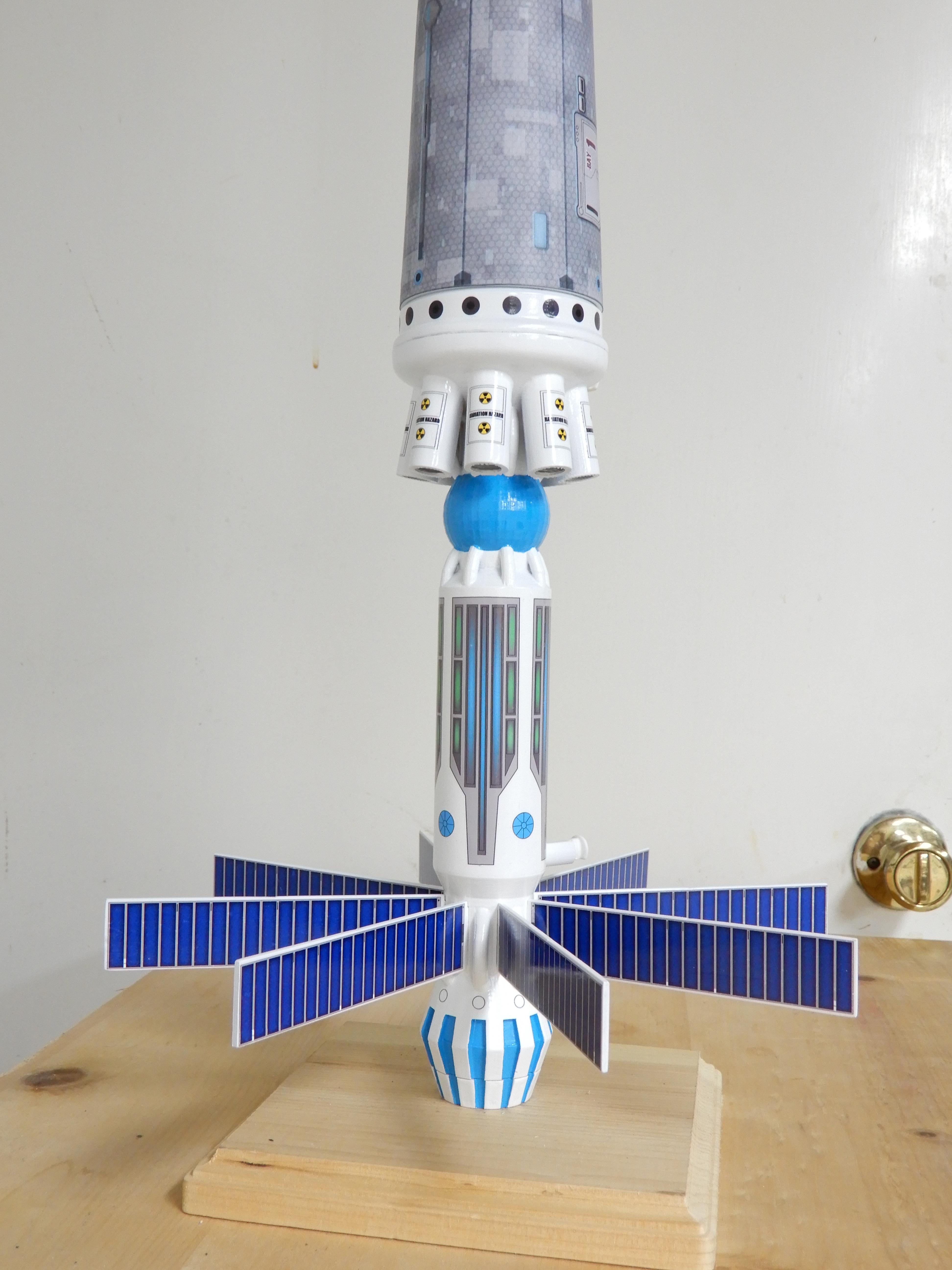
I started with the rear assembly that holds the motor. The directions show where you could attach the motor tube to the motor tube, so its up to you how you want to do it.
Start with the rear retainer cap. Put in the longest motor you plan to use in it (in my case, an E12). Press into the rear, making sure it goes all the way into the cap.

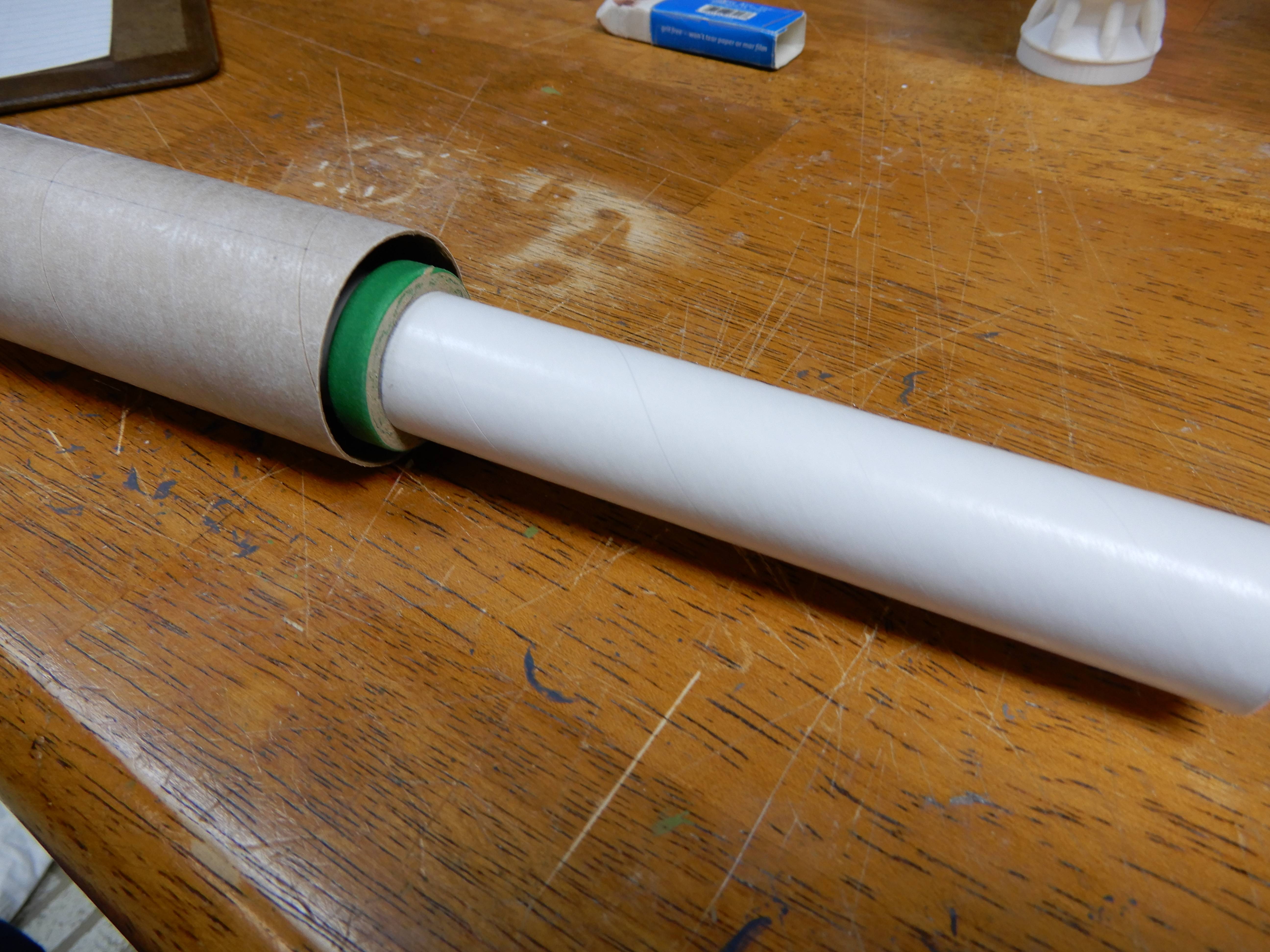
Take the BT-50 motor tube, and put a pencil line around the outside of the tube .75" from the end. Take one of the BT-50 to 55 green rings and slide it on the motor tube, leaving it about an inch in front of the pencil line. Put a line of wood glue all the way around the tube just ahead of the mark, and slide the ring onto the glue, ending up with the rear of the ring at the mark. Gotcha: make SURE that the front end of the ring is free of glue, as you will be using epoxy to attach it to the 3d printed rear assembly shortly. Let dry, and then add a bead of wood glue to the REAR of the ring to add strength.
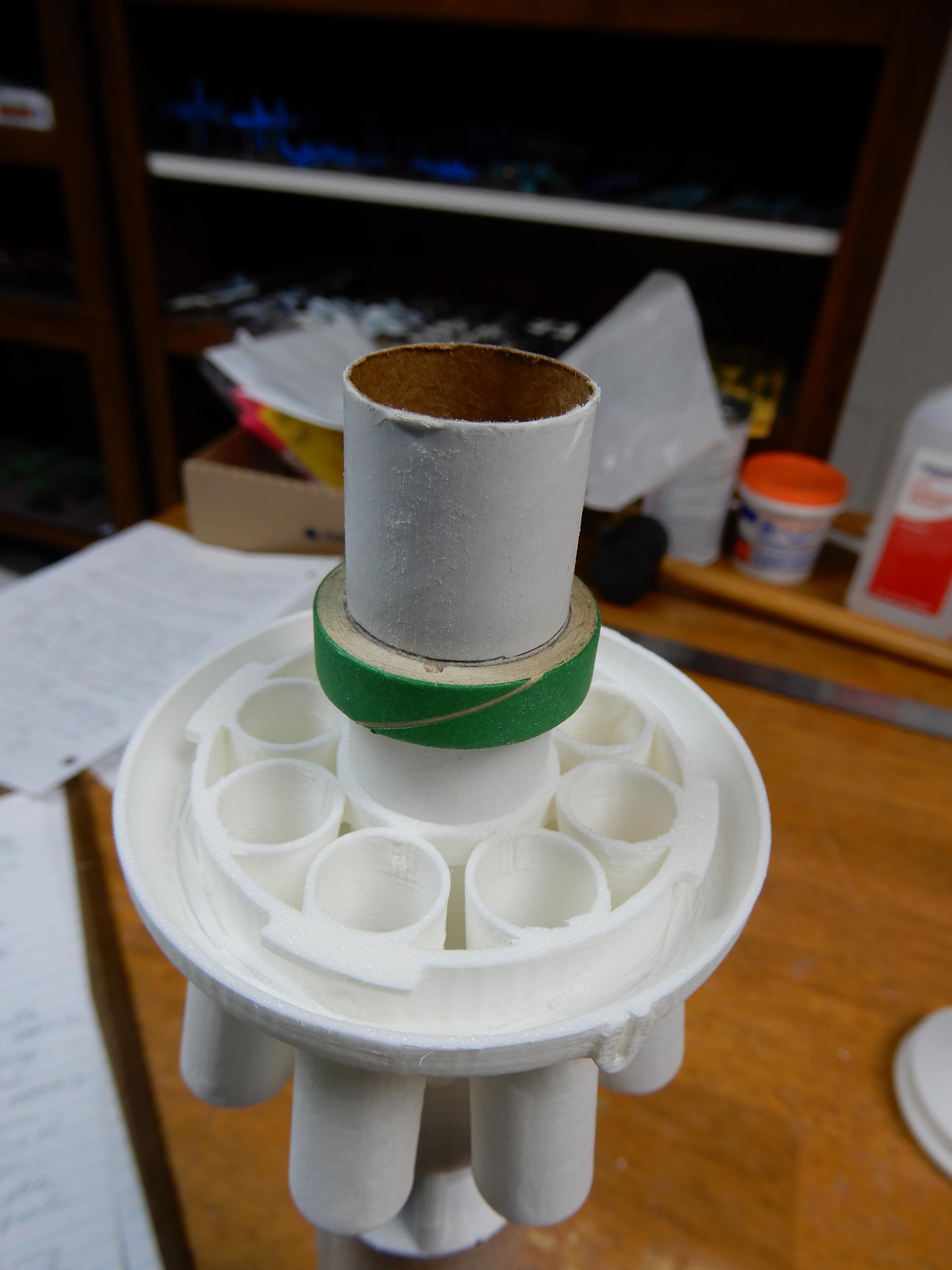
Next, put a bead of epoxy (15 or 30 minute preferred for more strength) on the front lip of the green ring. Slide it carefully into the rear opening of the rear engine assembly, and push all the way in. Using the engine retainer cap with motor inserted into it, slide the engine into the motor tube, turn the retainer cap to lock. Leave the retainer cap and engine in place, and stand the whole thing up so that the epoxy can flow downwards onto the 3d printed part. Let dry.
Turn the rear engine assembly over and put a bead of epoxy where the tube meets the front of the engine assembly to keep the tube from moving backwards. Let dry.
Put a line of wood glue on the inside of the motor tube, 3 1/4" from the rear end. Using the retainer cap and engine, push the 24mm engine block into place, and remove the engine+retainer so you don't glue it into place.
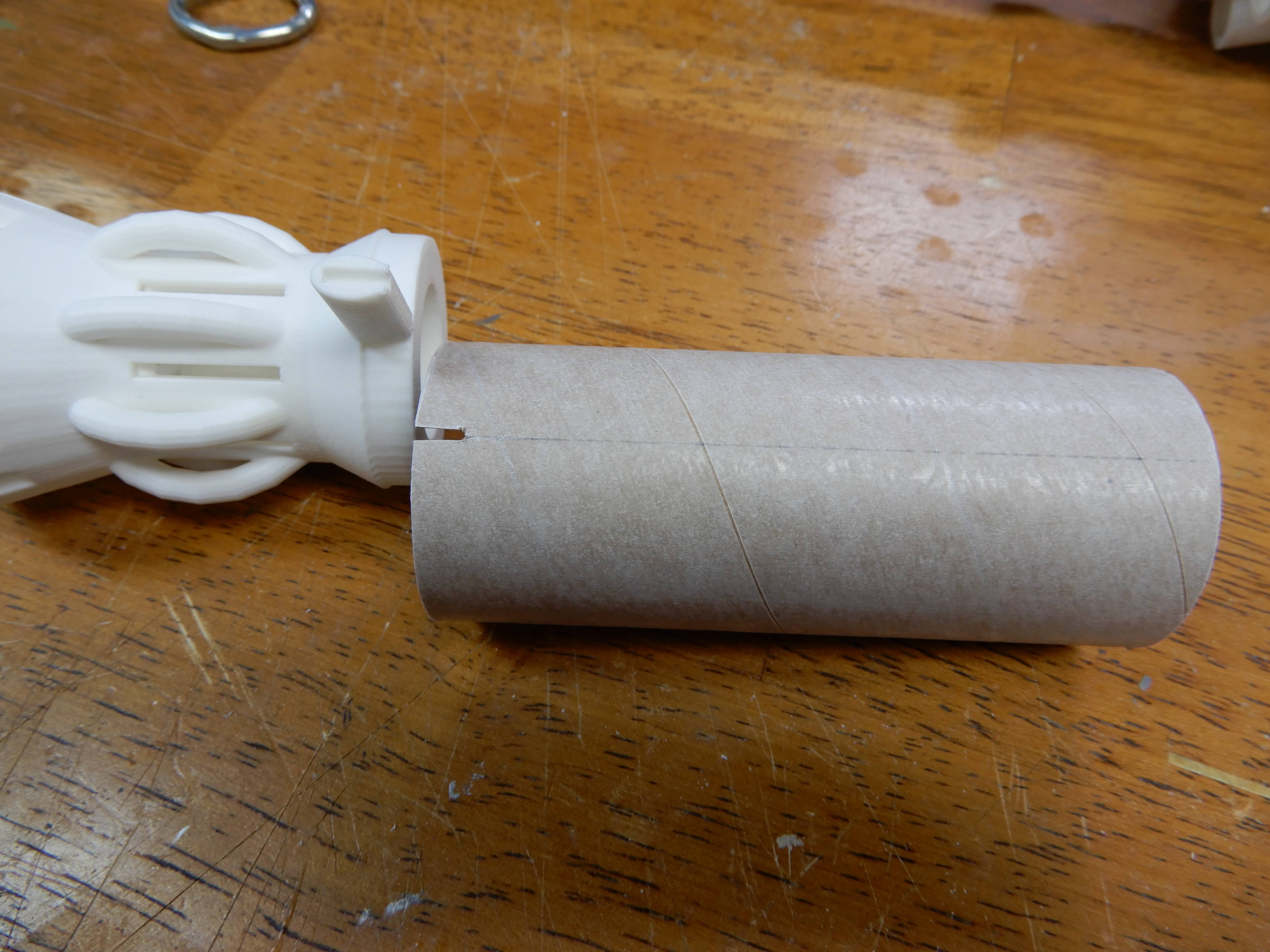
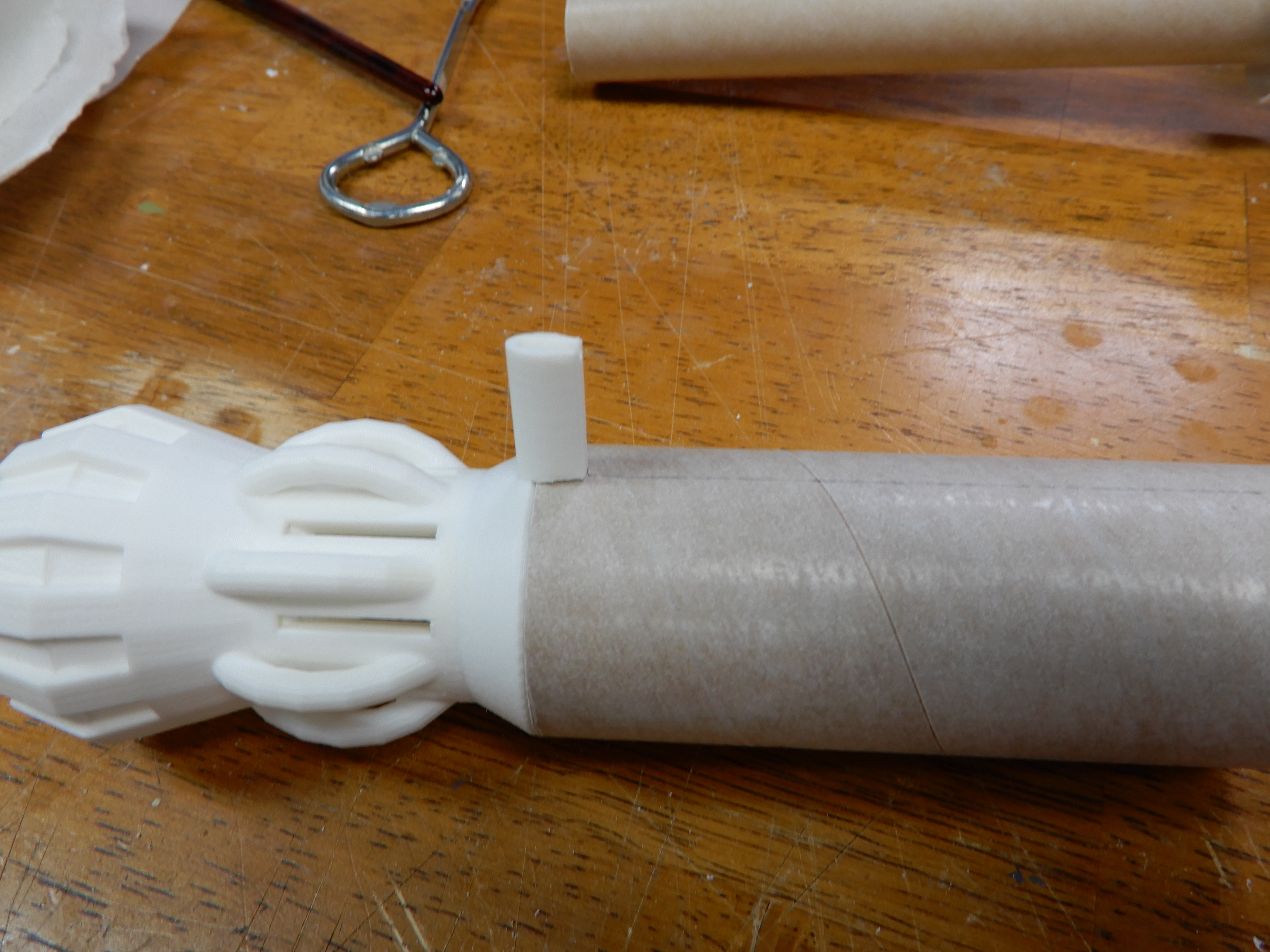
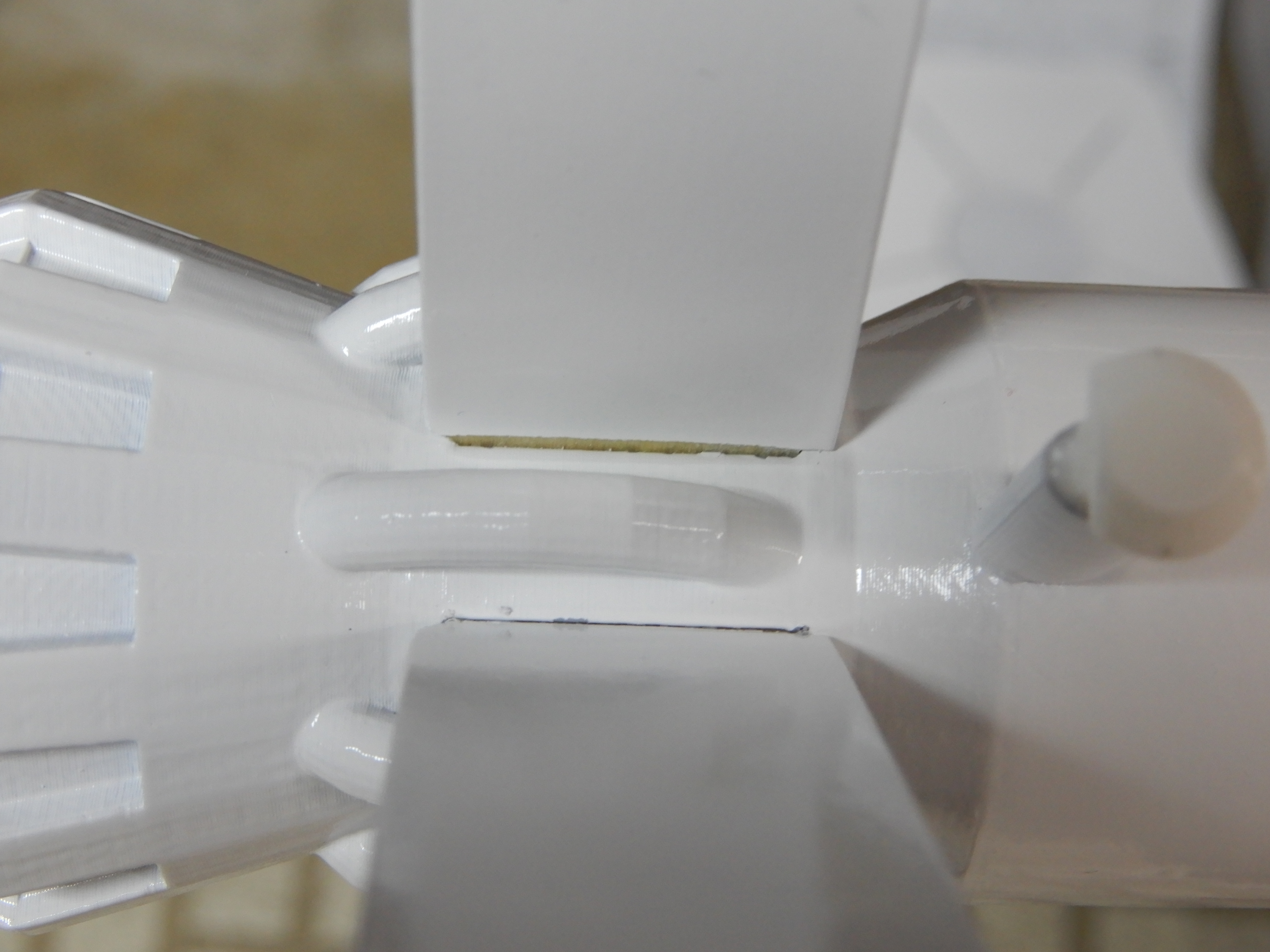
Taking the 4" BT-60 tube section, draw one line from one end to the other. Make a slot 1/16" wide x 1/4" long right on the line, to fit into the area under the pedestal on the rear engine assembly (for attaching the launch lug/rail "button" later on). Test fit it on the rear engine assembly, but don't glue it yet.
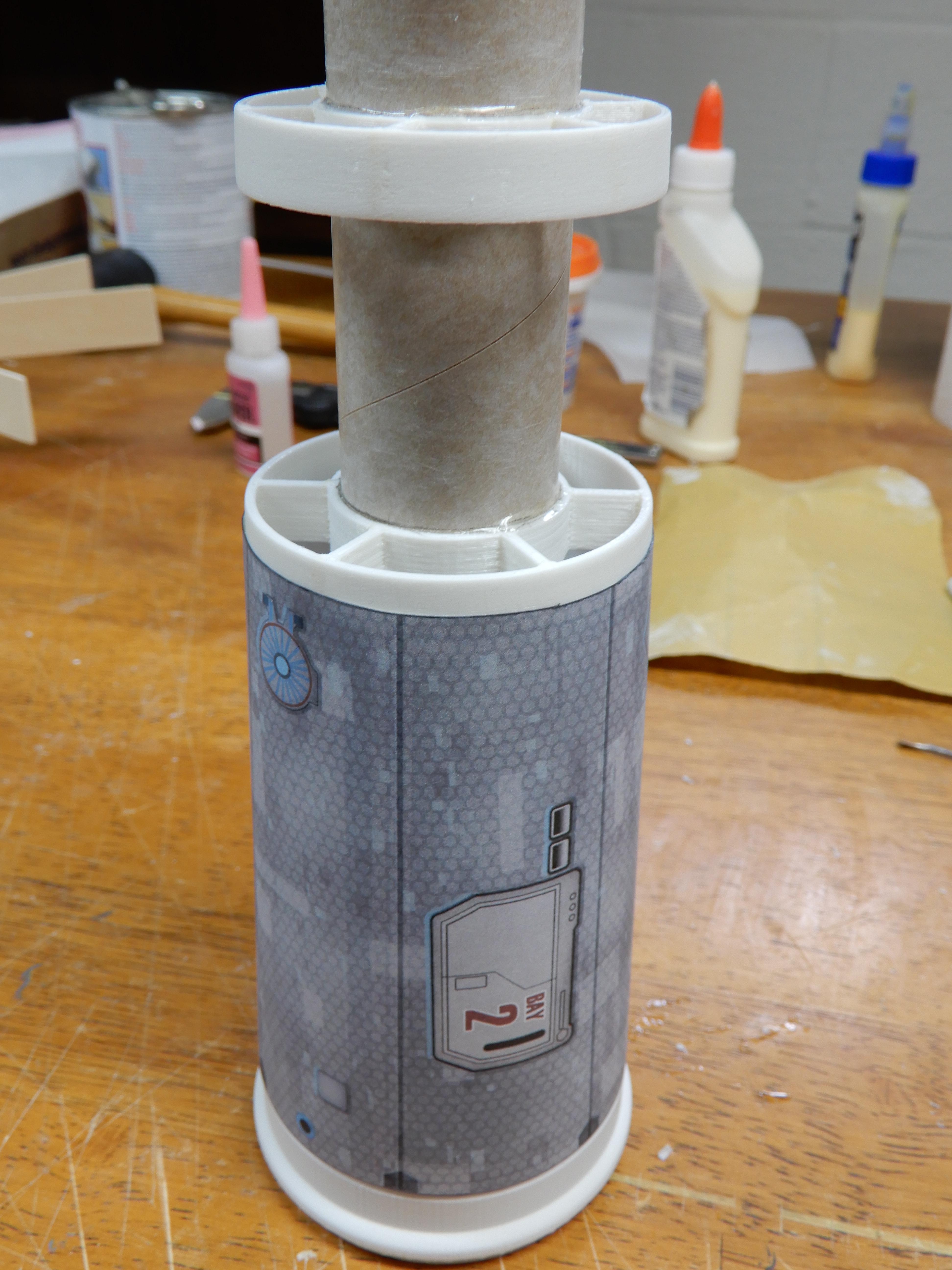
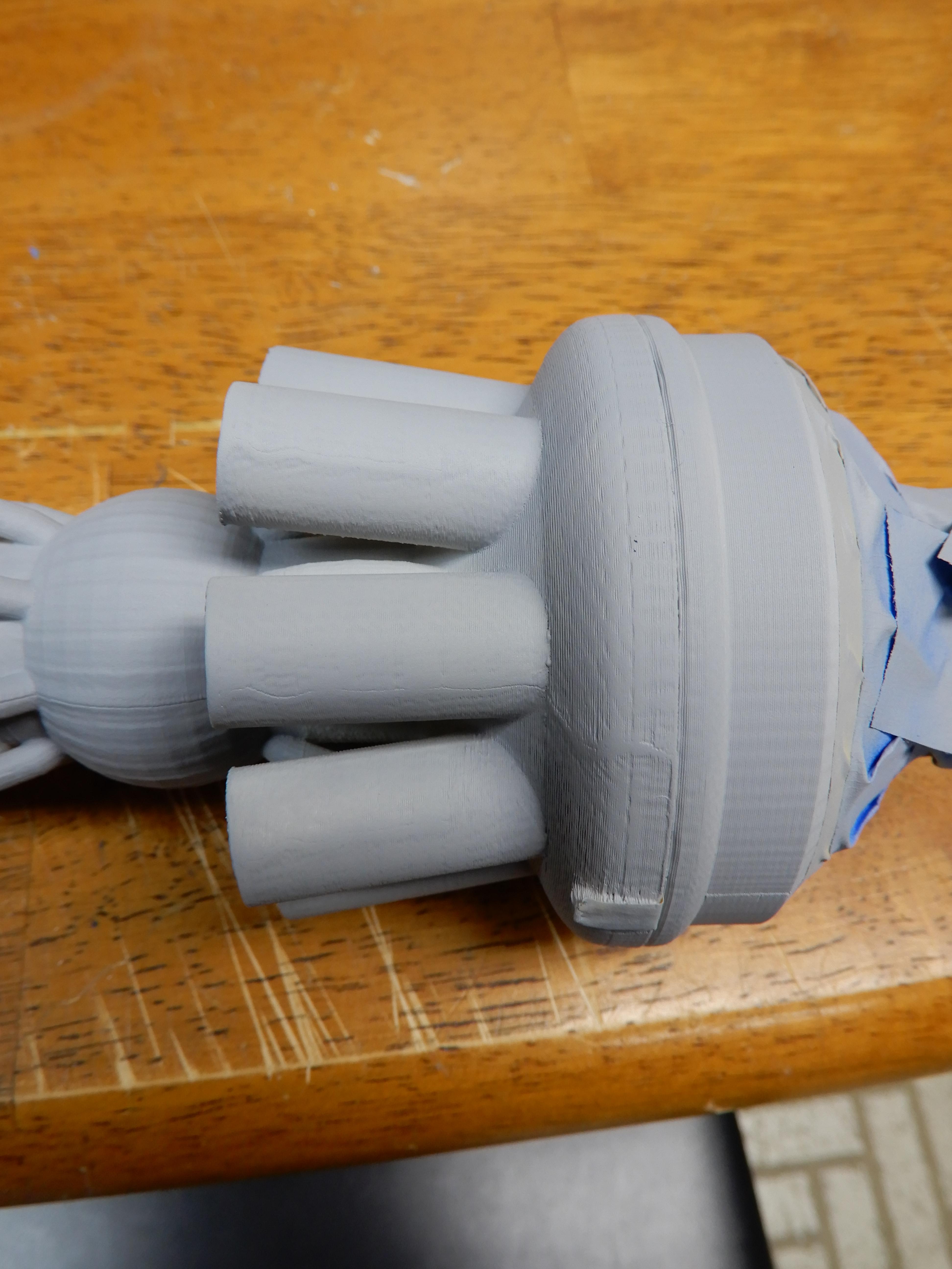
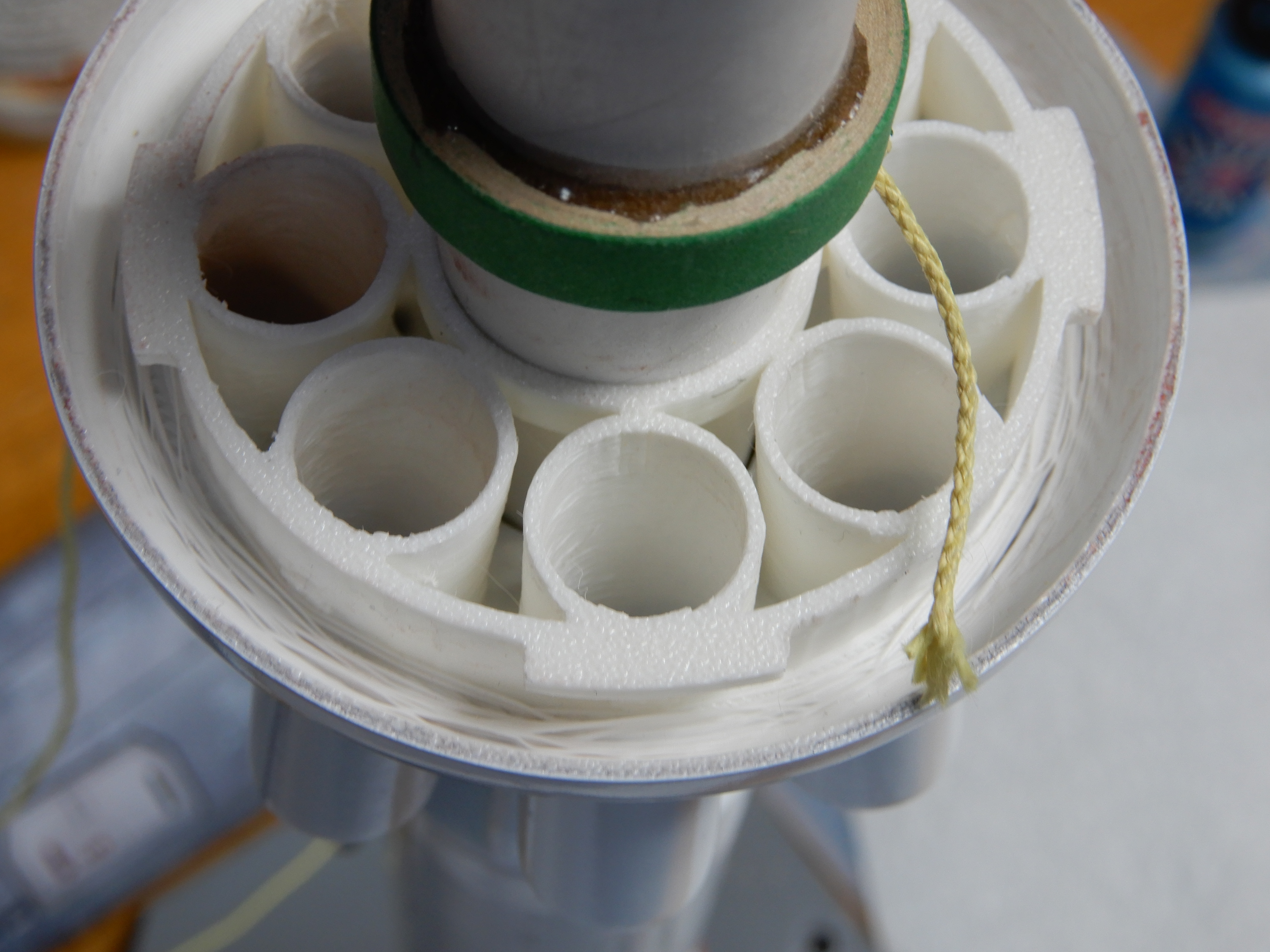
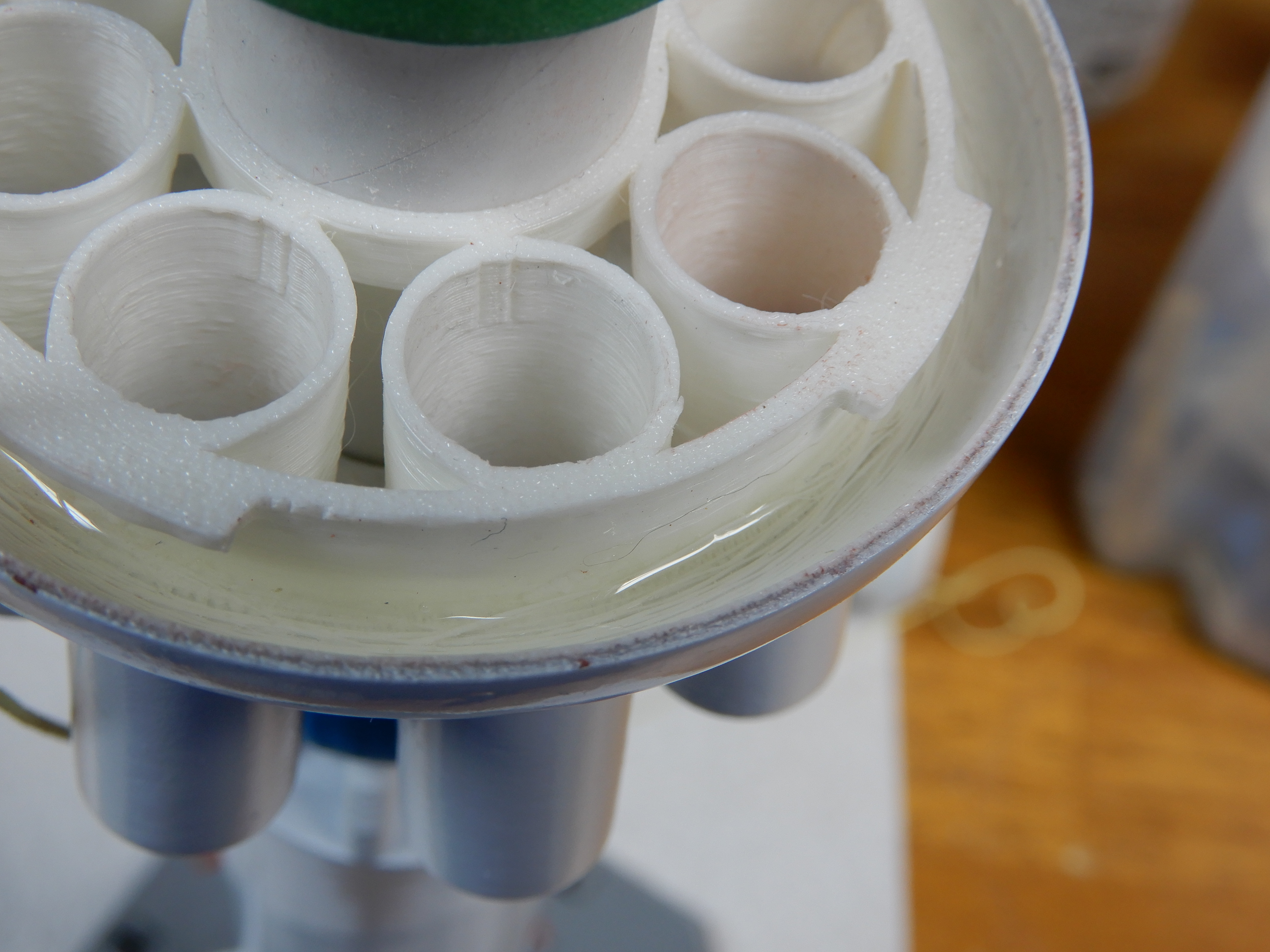
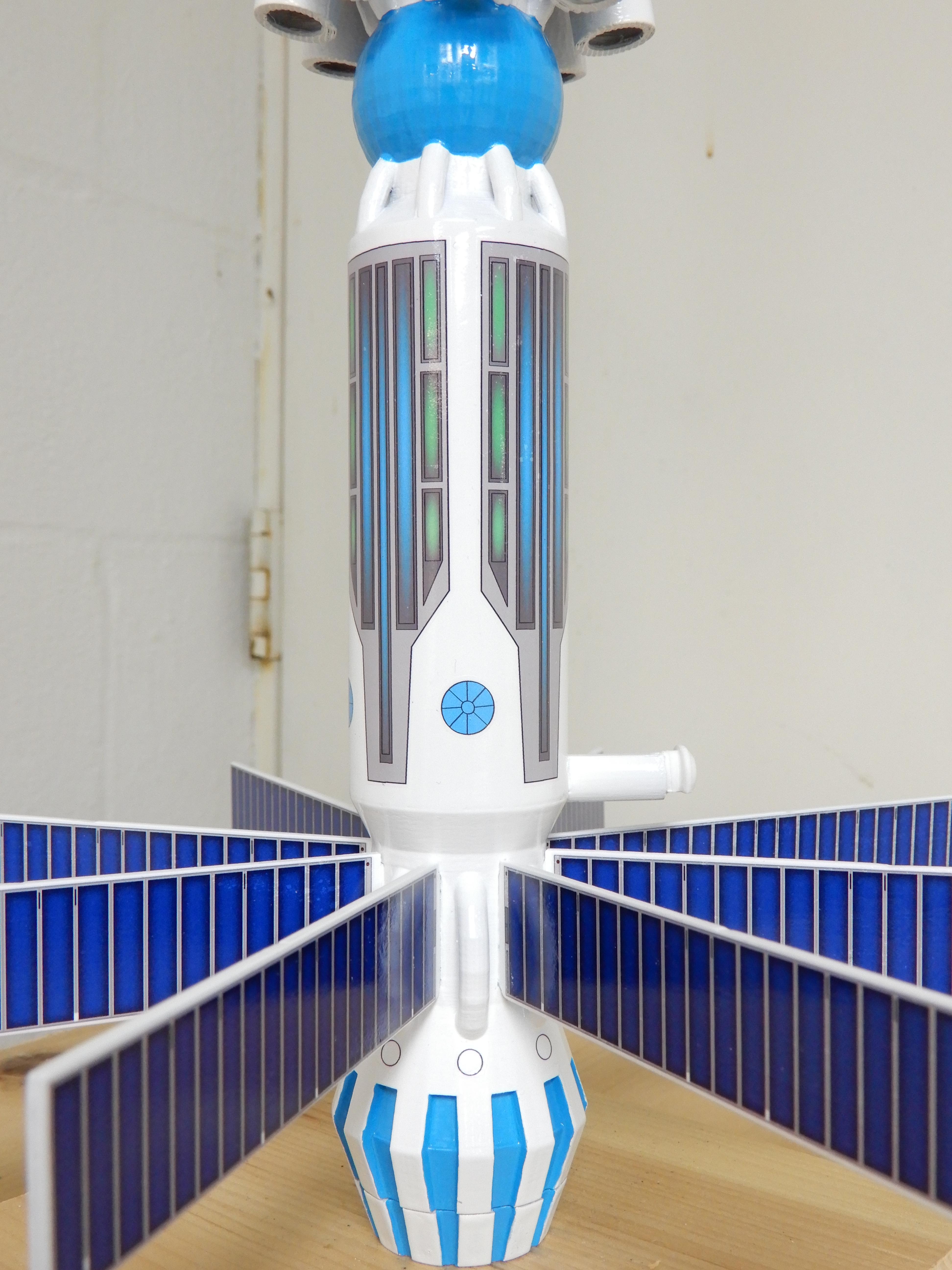
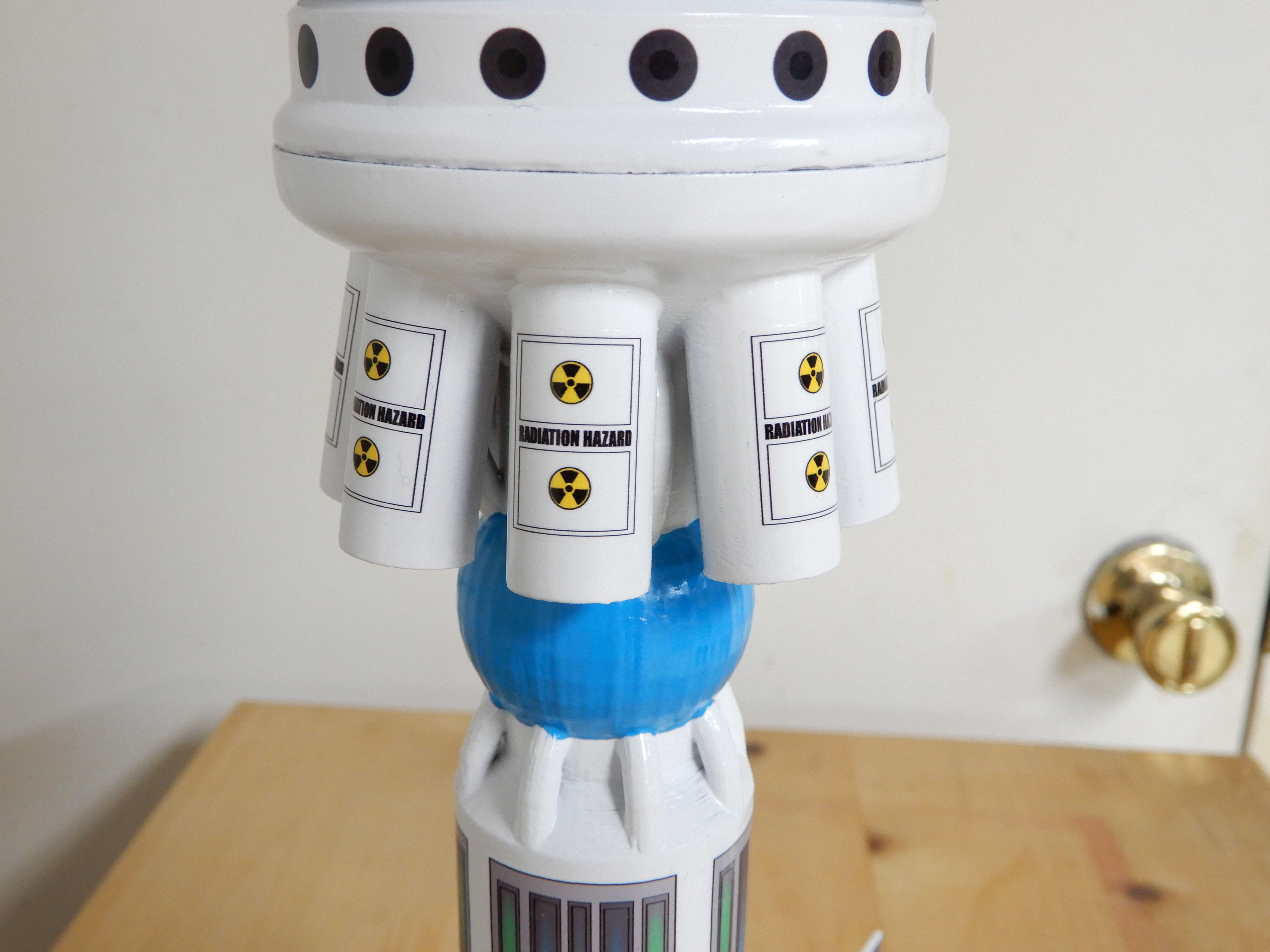
Slide an green ring (BT-55 to 50) onto the front of the BT-50 motor tube. Stop about an inch from the end of the tube, but don't glue it. Slide the rear half of the cluster assembly onto the tube, and press back until it meets the front of the engine assembly. Turn to lock a little bit. Unlock it, and carefully remove the rear half of the cluster assembly. You are using the rear half of the cluster assembly to position the green ring so it touches the inside of the part when epoxied into place.
Note where the green ring is, and mark both the front and rear edges with a pencil line. Slide off the BT-60 tube, exposing more of the motor tube. Move the green ring 1/4" FORWARD of the front line on the motor tube. Apply a bead of wood glue around the tube between the two lines, and slide the green ring down to fit between the two lines. IMMEDIATELY put the rear half of the cluster assembly back on to confirm that the ring isn't too far forward. If it is, gently press the cluster assembly backwards until it stops. Let dry. Add a bead of wood glue to the REAR end of the green ring. Leave the front edge of the green ring clean so you can epoxy it in the next step.
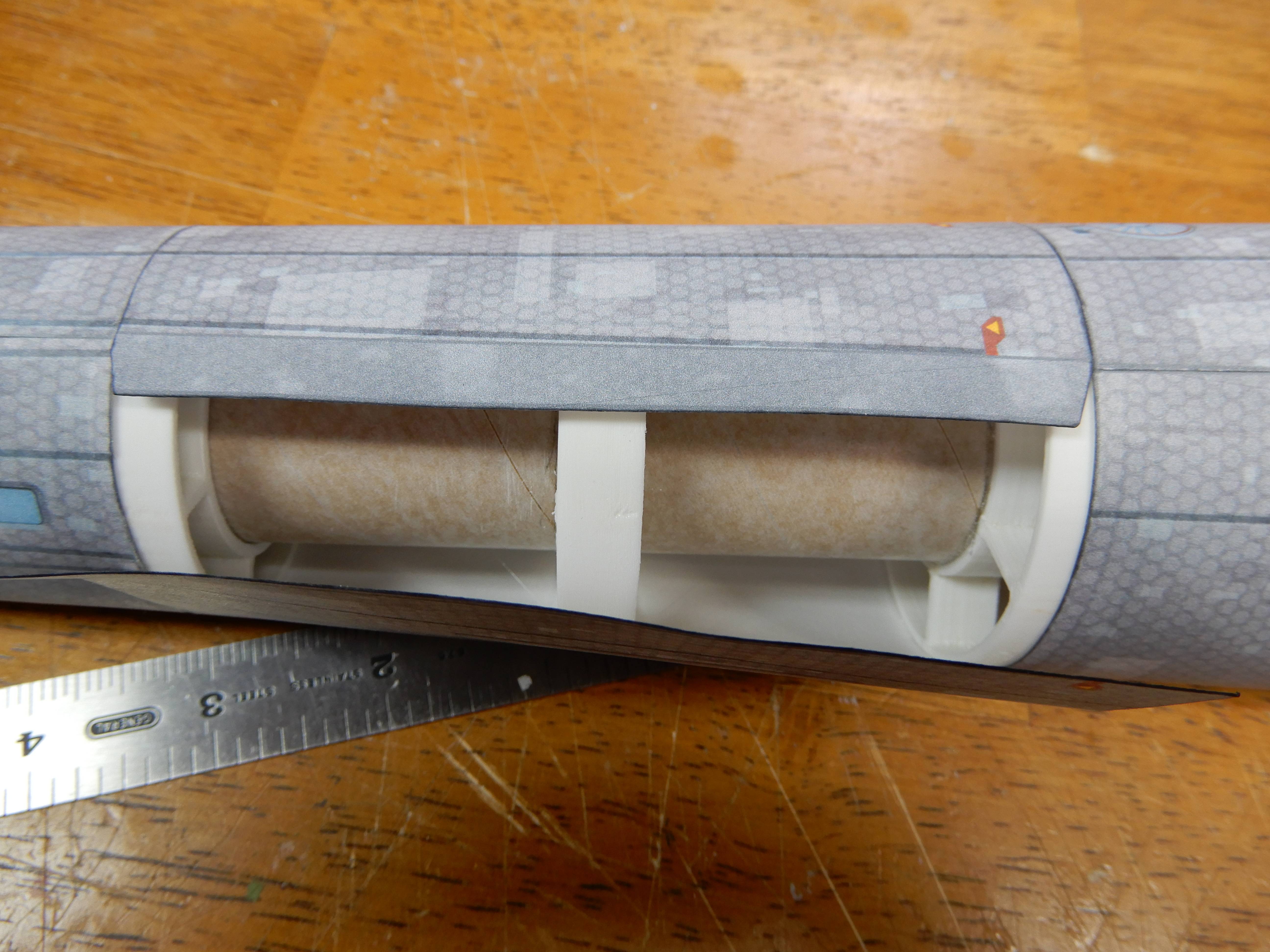
Put some epoxy on inside the rear 1/4" of the BT-60 tube section, and press onto the front shoulder of the engine assembly. You will be putting epoxy on the front 1/4" of the tube as well in the next step, so it may be easier to do it now. Also put some epoxy on the front edge of the green ring, so it will glue to the inside of the rear half of the cluster assembly.
GOTCHA: DO NOT put epoxy directly on the 3d printed part near the hole for the motor tube; it will get onto the motor tube and make a mess, making it harder to attach the shock cord mount in a later step. You want the motor tube to remain clean... I messed this up and had epoxy all over the outside of the motor tube, requiring me to quickly put on the shock cord mount when I wasn't quite ready. Wood glue isn't going to stick well to tube with a coating of epoxy on it, despite using alcohol to remove the epoxy, so beware.
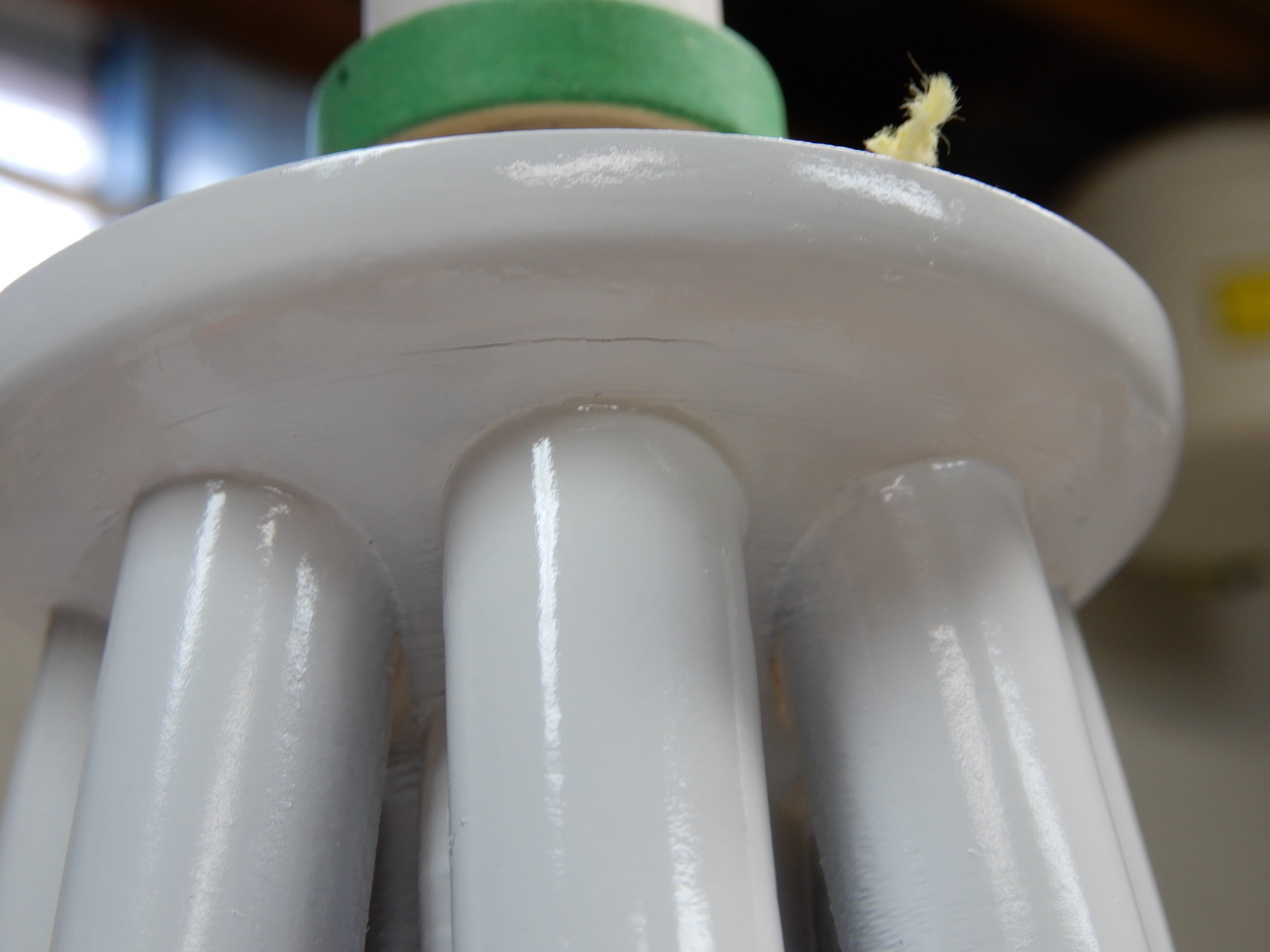
Carefully slide the rear half of the cluster assembly onto the motor tube, and go all the way back until it stops. Turn the lock a little to ensure the part is secured. Stand the assembly upside down (front end of the motor tube is down) so the epoxy can drip onto the 3d printed cluster assembly. You could put some expoxy where the cluster assembly joins the motor tube if you want. If you do, be careful to not get any glue away from the joint on the tube (keep the tube clean so you have room to work and attach the shock cord mount later on).
Attaching the shock cord mount:
I decided to use 14' of #200 kevlar. Take the third green ring (BT-55 to 50), and put an notch on the inside of the ring wide enough to allow the kevlar cord to pass through. Slide ring onto the motor tube, with the front edge about an inch from the front end of the motor tube. The distance isn't critical, so long as you can take the front half of the cluster assembly and slide it all the way down and lock it. Glue the ring in place, making sure that no glue gets into the notch. I used a piece of plastic tubing to fill the hole. You should use wood glue to attach the ring, but as I had messed up in the previous step, getting epoxy all over the outside of the motor tube, I decided that the wood glue probably wouldn't stick and therefore used epoxy to attach the ring.
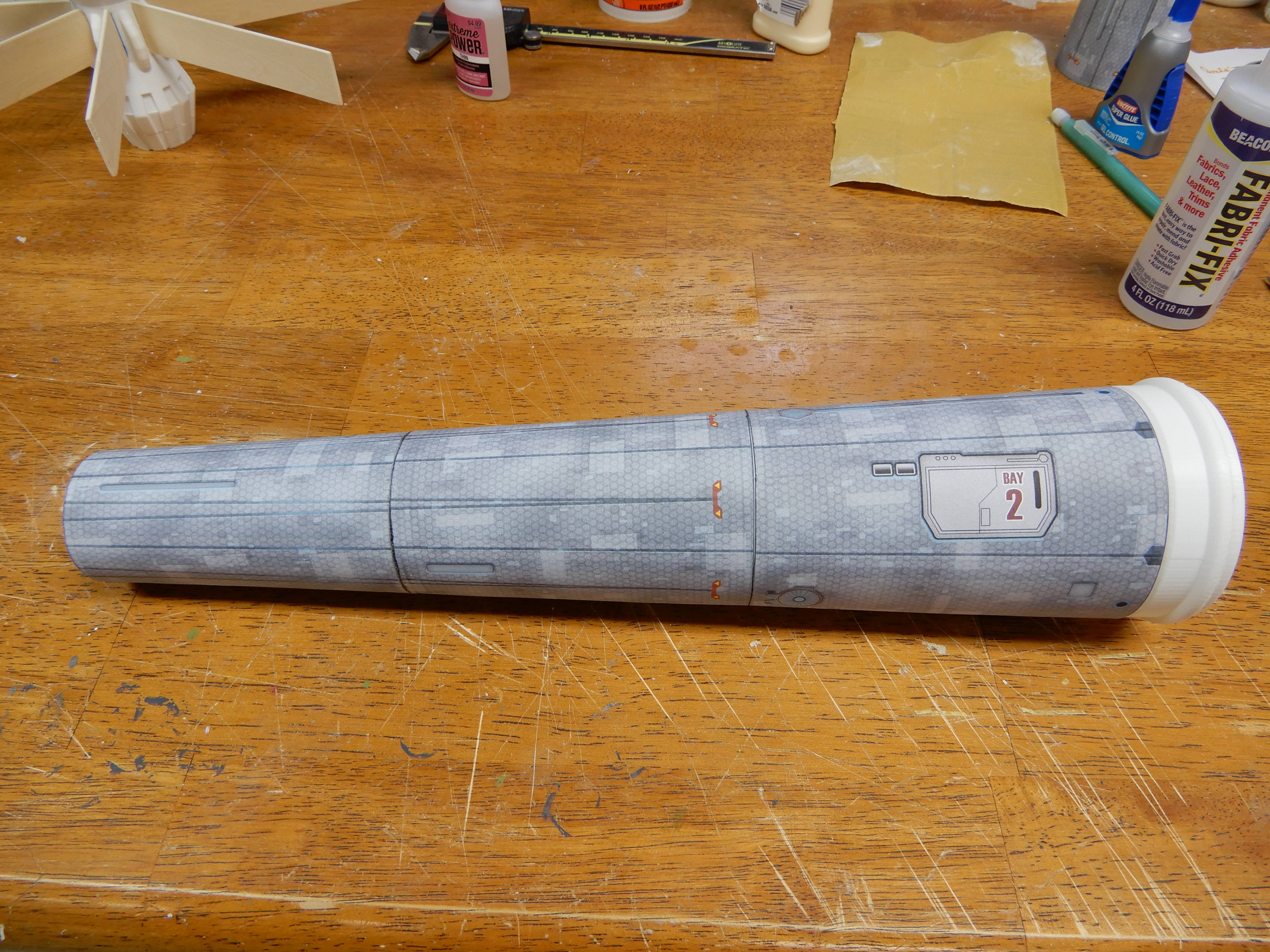
Thats all for now, will post more soon.
Pre-construction, I sanded most of the 3d printed ABS parts smooth; I decided I didn't want to mess with the using ABS bits and acetone to smooth everything.
In addition to what was provided in the builders kit, I also needed 3 x Estes green centering rings (BT-50 to 55), and an 24mm engine block.
One also needs the following body tubes:
BT-20 approx 9 7/16" long, BT-50 approx 11 7/8" long, BT-55 approx 12 1/4" long (leave a little extra (1/2"? ) on the length for reasons that will become apparent later), and BT-60 4" long. Sand all of the tubes to remove the glassine.
I started with the rear assembly that holds the motor. The directions show where you could attach the motor tube to the motor tube, so its up to you how you want to do it.
Start with the rear retainer cap. Put in the longest motor you plan to use in it (in my case, an E12). Press into the rear, making sure it goes all the way into the cap.
Take the BT-50 motor tube, and put a pencil line around the outside of the tube .75" from the end. Take one of the BT-50 to 55 green rings and slide it on the motor tube, leaving it about an inch in front of the pencil line. Put a line of wood glue all the way around the tube just ahead of the mark, and slide the ring onto the glue, ending up with the rear of the ring at the mark. Gotcha: make SURE that the front end of the ring is free of glue, as you will be using epoxy to attach it to the 3d printed rear assembly shortly. Let dry, and then add a bead of wood glue to the REAR of the ring to add strength.
Next, put a bead of epoxy (15 or 30 minute preferred for more strength) on the front lip of the green ring. Slide it carefully into the rear opening of the rear engine assembly, and push all the way in. Using the engine retainer cap with motor inserted into it, slide the engine into the motor tube, turn the retainer cap to lock. Leave the retainer cap and engine in place, and stand the whole thing up so that the epoxy can flow downwards onto the 3d printed part. Let dry.
Turn the rear engine assembly over and put a bead of epoxy where the tube meets the front of the engine assembly to keep the tube from moving backwards. Let dry.
Put a line of wood glue on the inside of the motor tube, 3 1/4" from the rear end. Using the retainer cap and engine, push the 24mm engine block into place, and remove the engine+retainer so you don't glue it into place.
Taking the 4" BT-60 tube section, draw one line from one end to the other. Make a slot 1/16" wide x 1/4" long right on the line, to fit into the area under the pedestal on the rear engine assembly (for attaching the launch lug/rail "button" later on). Test fit it on the rear engine assembly, but don't glue it yet.
Slide an green ring (BT-55 to 50) onto the front of the BT-50 motor tube. Stop about an inch from the end of the tube, but don't glue it. Slide the rear half of the cluster assembly onto the tube, and press back until it meets the front of the engine assembly. Turn to lock a little bit. Unlock it, and carefully remove the rear half of the cluster assembly. You are using the rear half of the cluster assembly to position the green ring so it touches the inside of the part when epoxied into place.
Note where the green ring is, and mark both the front and rear edges with a pencil line. Slide off the BT-60 tube, exposing more of the motor tube. Move the green ring 1/4" FORWARD of the front line on the motor tube. Apply a bead of wood glue around the tube between the two lines, and slide the green ring down to fit between the two lines. IMMEDIATELY put the rear half of the cluster assembly back on to confirm that the ring isn't too far forward. If it is, gently press the cluster assembly backwards until it stops. Let dry. Add a bead of wood glue to the REAR end of the green ring. Leave the front edge of the green ring clean so you can epoxy it in the next step.
Put some epoxy on inside the rear 1/4" of the BT-60 tube section, and press onto the front shoulder of the engine assembly. You will be putting epoxy on the front 1/4" of the tube as well in the next step, so it may be easier to do it now. Also put some epoxy on the front edge of the green ring, so it will glue to the inside of the rear half of the cluster assembly.
GOTCHA: DO NOT put epoxy directly on the 3d printed part near the hole for the motor tube; it will get onto the motor tube and make a mess, making it harder to attach the shock cord mount in a later step. You want the motor tube to remain clean... I messed this up and had epoxy all over the outside of the motor tube, requiring me to quickly put on the shock cord mount when I wasn't quite ready. Wood glue isn't going to stick well to tube with a coating of epoxy on it, despite using alcohol to remove the epoxy, so beware.
Carefully slide the rear half of the cluster assembly onto the motor tube, and go all the way back until it stops. Turn the lock a little to ensure the part is secured. Stand the assembly upside down (front end of the motor tube is down) so the epoxy can drip onto the 3d printed cluster assembly. You could put some expoxy where the cluster assembly joins the motor tube if you want. If you do, be careful to not get any glue away from the joint on the tube (keep the tube clean so you have room to work and attach the shock cord mount later on).
Attaching the shock cord mount:
I decided to use 14' of #200 kevlar. Take the third green ring (BT-55 to 50), and put an notch on the inside of the ring wide enough to allow the kevlar cord to pass through. Slide ring onto the motor tube, with the front edge about an inch from the front end of the motor tube. The distance isn't critical, so long as you can take the front half of the cluster assembly and slide it all the way down and lock it. Glue the ring in place, making sure that no glue gets into the notch. I used a piece of plastic tubing to fill the hole. You should use wood glue to attach the ring, but as I had messed up in the previous step, getting epoxy all over the outside of the motor tube, I decided that the wood glue probably wouldn't stick and therefore used epoxy to attach the ring.
Thats all for now, will post more soon.
Last edited:

 !!!
!!! 