12volt Muti-Pad Launch Controller

The Rocketry Forum

Help Support The Rocketry Forum:

This site may earn a commission from merchant affiliate links, including eBay, Amazon, and others.

Flash

Well-Known Member
Joined
Jan 22, 2009
Messages
639
Reaction score
48
I was looking at making a simple single to muti-launch Rocket Controller. So please look over my design and feel free to give me your pros and cons and recommendations. The design only uses one fire button, you select the pads you want to fire from 1 to up to 6 rockets at the same time. Drag race as some call it.

Also, do I really need the 470ohm resistors with bright LED lights?

Power recommendations would be nice to. I was thinking about possibly using my 20v drill battery packs for power but I wonder how they will perform rated at only 3amps?

Thank you!
 

Attachments

  • 2022 Launch Pad Single Button Design.png
    2022 Launch Pad Single Button Design.png
    120.5 KB · Views: 3
470ohm 1/4W is the standard for 3v 20mA LEDs like the 5mm through-hole ones. Assuming 12v source, what's the voltage drop over the diode and what's the current needs? I have some 5w green LEDs that have a 6v to 7v drop and need 300mA and I use 33ohm 2W resistor for 12v source. That 5W LED can be seen in daylight from 100ft away without issue.
 
Here's a simpler version using only 1 LED for continuity confirmation. Or you can replace the LED with a 5 volt beeper.
For the battery I would suggest a 3 Cell Lipo rated 2000ma with a discharge of at least 10C.
S1,S2 and the Fire Button should be rated at 15 amps minimum. For the Pad select switches 5 amps would be sufficient.
And don't think I didn't notice the switches, LEDs and resistors were copied from one of my previous post. :p
1661560687392.png
 
Last edited:
Personally, I would keep the individual continuity LEDs as they are, but just remove the redundant push buttons from the ignition output lines. Just keep the main fire button and the other toggle switches, etc.
 
Last edited:
Personally, I would keep the individual continuity LEDs
I normally do which allows one to monitor igniter continuity at all times. However in a simple multi pad system such as this one there is a feedback path which can show igniter continuity when no igniter is connected as shown below. When an igniter is connected to only pad 1 as an example it shows continuity. If pad switches 1 and 2 are selected pad 2 will show a false continuity. Installing 5 amp diodes in series with the pad select switches as shown on pad 3 will eliminate this feedback path but does add additional components.
Another reason for the switches is because some people are concerned of that small current (20ma) flowing through the igniter continuously.
1661564073427.png
 
Sorry friends, my error, the individual switches aren’t going to be there. I had another idea and through I removed them 🙄
 
The last diagram is totally correct and what I had in mind. 😊
 
Also, do I really need the 470ohm resistors with bright LED lights?
Yes you do need the resistors. An LED is basically a short circuit, so would attempt to pull an infinite amount of current without the current limiting resistor, or a current limited source. You need to pick an appropriate resistor value for the voltage you are using. For example, the 470 ohm resistors are technically OK for a "3V" LED when using 12 volts (12V-3V)/470 Ohm ~= 20mA, which is OK for most LEDs. For more common 2V LEDs, you would need a larger resistor. If you use a 20V battery with 470 Ohm resistor, then you would get almost 40mAs through the LED. Unless you are using high power LEDs that would destroy the LEDS, if not right away, then very soon. If it was me, I would use 2.2K resistors. That would be 4mA for 12V and 8mA for 20V. Much safer current levels, and more than enough for this application.
Power recommendations would be nice to. I was thinking about possibly using my 20v drill battery packs for power but I wonder how they will perform rated at only 3amps?
That depends on the pack. If you have a NiCd or NiMH battery pack it would probably OK. Thou it probably would not fire all six at once. If your pack uses lithium batteries, you might have a problem. At 20V an Estes igniter will attempt to draw > 30A! Most lithium batteries have low enough internal resistance to attempt to deliver most of that current. That much current could easily damage your batteries, or more likely trigger a battery protection circuit in the pack. If you want to use a 20V/3A battery pack, you should put a 5-10 Ohm high wattage resistor in series with the igniters.

Another reason for the switches is because some people are concerned of that small current (20ma) flowing through the igniter continuously.
Yeah, I am one of those people. Doesn't make sense to me to have a live circuit, even current limited, when someone is attaching wires to a igniter stuffed in a pyro device an inch or so form their hands and probably less than a foot from their face. Especially if you are actually using 20mA. That is enough to occasionally set off the old Quest igniters, and possibly enough to set off the e-match style that are being used by some people. Why take a nice safe hobby, and turn it into a crap shoot? Yes, you could just turn off the master switch, but how many times are you going to forget to do that?

Personally, I would move the continuity connection from between the master and arm switches to after the arm switch, the change to arm switch to a momentary switch. You would still be able to check the continuity of all the igniters at once, but no current could flow unless someone was holding down the arm button down.
 
Sorry for the delay in replying. I have built two multi Launch controllers over the years and in both cases, I had a fire button for each pad. In both cases I wired a individual continuity testers on each side of each fire button which is the more traditional way of doing that. Due to trying to go to one fire button and looking at other diagrams post, that’s what lead me to this layout. i didn’t know about the diodes being needed, which is great in learning. If I use momentary switches for continuity testes, seems that would do away with the drag race option?
 
My equipment pages.

I used a1K resistor with a high brightness green LED because I need to see it at 30 feet or so. For up close use, much less current is required. Oh, go for a diffused LED so you don't have to be in the tiny output beam of a non-diffused part.
 
If I use momentary switches for continuity testes, seems that would do away with the drag race option?
Not at all. Individual continuity buttons as shown in post #5 will eliminate the diodes as well.
The Wilson system as an example uses individual buttons and a beeper to confirm continuity.
It all depends on how you want the system to operate. Momentary or continuous continuity confirmation.
 
Dummy me posted the wrong diagram from the start. I've attached the one I meant to post which is based more on Sghioto's last diagram post but without the diodes.
I'm not against the diodes, as I mentioned before, I didn't even realize I needed them:) That's really why I posted here in the first place. I knew that I would get some great ideas, improvements to include the all important safety improvements.

I also didn't even pickup on your post 5 individual continuity testers either. I saw those buttons as individual fire buttons, lol.

I guess they will only work on each properly connected rocket on the pad, right?
 

Attachments

  • 2022 Launch Pad Single Button Design.png
    2022 Launch Pad Single Button Design.png
    111.1 KB · Views: 0
You don't have to add the diodes as long as you are aware of the false continuity I spoke of before. Looking at your latest attachment without the diodes installed the situation is like this:
Say you have rockets on pads 1,3 and 5 with the igniters connected. On the control box LEDs 1,3 and 5 will be illuminated and these will be the pads you select either individually or some combination as for a drag race. If for some reason you want select a pad that does not show continuity at the control box the LED for that pad will illuminate when the pad is selected. But now you are aware that this is false as turning off the pad switch turns off the LED.
 
So if I have things correct at this point, I have 3 choices. Do nothing and be aware of the false reading if empty pad is selected, add diodes to correct that by only allowing current in one direction or adding a push button continuity checker like shown in post 5.

I think I like keeping the diagram just shared and adding the diodes just before the selector switches if I've got it right?
Question, does it matter if the diodes are pass the selector switch as long as they are before where the continuity wires connect?

I think I'll pass on the Drill battery idea I was thinking about. So for a 12V system, could you give me some recommendations on specs I should be looking for on the following components built with 16ga wire. I would like the controller to be Quest ignitor friendly to.

Large fire button >
Selector switches >
Key Switch >
Bright LED's >
Resistors >
Diodes >
Door Chime >
I like the chime better than a buzzer, just want it to go off when the master switch is on.

Thank you!
 
Last edited:
Question, does it matter if the diodes are pass the selector switch as long as they are before where the continuity wires connect?
This is how I suggest the system wired.
Install the diodes before the pad switches for easier installation.
Use 1k resistors and get 5mm diameter super bright white LEDs. Trust me, white LEDs are more visible from a distance. LED current only 10ma, super safe as the Quest igniters require appx 120ma. at best.
Wire the common connection on the LED resistors to the N.O. side of the S1. This way you can confirm continuity at the pads and before the system is armed.
Wire the chime to the N.O. side of S2 otherwise that chime is going to be annoying during setup. The voltmeter will indicate when the master switch is ON.

1661708766070.png
 
Last edited:
Below is a list of items I'm considering for this project. Please look them over and give me your thoughts and recommendations.


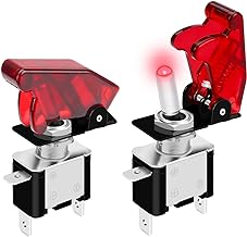
DaierTek Red 12 Volt LED Lighted Toggle Switch with Aircraft Guard Safety Flip Cover 12V DC 20A Heavy Duty Covered Illumin...

DaierTek Red 12 Volt LED Lighted Toggle Switch with Aircraft Guard Safety Flip Cover 12V DC 20A Heavy (to light up for each selected pad)​


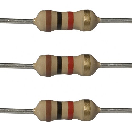
  • E-Projects 100EP5141K00 1k Ohm Resistors, 1/4 W, 5% (Pack of 100)
Click image to open expanded view


E-Projects 100EP5141K00 1k Ohm Resistors, 1/4 W, 5% (Pack of 100)​


Click image to open expanded view


100pcs /lot Transparent Round 5mm 3V Super Bright Water Clear Light LED Bulbs Emitting Diode F5 (White)​


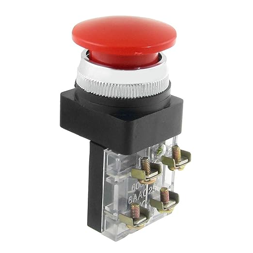
  • uxcell a12042700ux0294 AC 600V 6A 38 mm 1.5" Red Sign Momentary Mushroom Push Button Switch 1 No 1 NC

Click image to open expanded view


uxcell a12042700ux0294 AC 600V 6A 38 mm 1.5" Red Sign Momentary Mushroom Push Button Switch 1 No 1 NC​

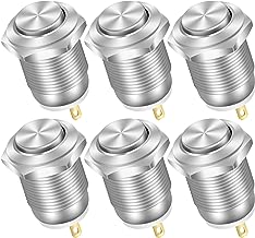
DaierTek 6pcs 12mm Momentary Push Button Switch 12V Waterproof Power Pushbutton Small Round Chrome Stainless Metal 2pin N/O

DaierTek 6pcs 12mm Momentary Push Button Switch 12V Waterproof Power Pushbutton Small Round Chrome Stainless Metal 2pin N/O (if I decide to do the push button continuity tester for each pad)

1661885288038.png


APACHE

3800 Weatherproof Protective Case, Large, Orange​

 
An observation: If you're aiming to keep the system e-match/Q2G2 safe, be sure to take into account the LEDs in the switches.

This thread has been very interesting for me.
 
Yes Sir BEC. I actually didn't list the diodes that I may be using just before each pad selector switch. Guess that will depend on if I using the continuity buttons or not. When I figure it out, I'll be posting a final diagram for comment before I actually order the stuff and start work. I appreciate your observation.

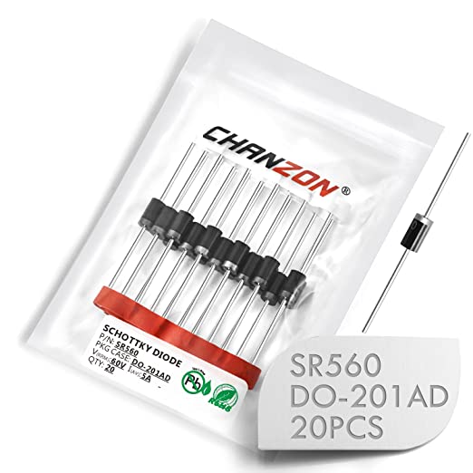
  • (Pack of 20 Pieces) Chanzon SR560 (SB560) Schottky Barrier Rectifier Diodes 5A 60V DO-201AD (DO-27) Axial 5 Amp 60 Volt

Click image to open expanded view


(Pack of 20 Pieces) Chanzon SR560 (SB560) Schottky Barrier Rectifier Diodes 5A 60V DO-201AD (DO-27) Axial 5 Amp 60 Volt​


Any thoughts from anyone on the other components would be appreciated.
 
One problem I see is the main Fire button. That switch is only rated at 6 amps and because the system can launch 6 rockets simultaneously it really needs to be rated at 15 amps minimum along with the Master key switch. If you only use the Quest igniters it's OK but a lot of igniters draw a couple of amps or more although only briefly.
There is also a problem with the LEDs in the pad select switches they are only going to light up when the main Fire button is pressed.
If you want a LED to light up when a pad is selected you will need to install discrete LEDs and use DPST switches for the pad select.
 
Last edited:
See what you are saying. I'll just drop the led toggles. Would going with an automotive relay be even better than a 15amp fire button?
 
I use these instead of physical relays. With physical relays you have to worry about welded contacts so adding a thermal reset breaker or PTC thermistor would be needed.

LGDehome 10PCS DC 5V-36V 15A(Max 30A) 400W Dual High-Power MOS Transistor Driving Controller Module FET Trigger Switch Drive Board 0-20KHz PWM Electronic Switch Control Board DC Motor Speed Controller https://a.co/d/j7WFF5L

Works very well with microcontrollers but could be used as normal relay. At $1.50 each, pretty cheap too. I'm sure you could find them cheaper on ebay, aliexpress or banggood.

And I used slightly different schottky diodes. 15A 45V 15SQ045 Yours could work but 5A rating would worry me if you use LiPo batteries that can source significant current and someone has a big cluster on the pad.
 
I use to own a 1/24 scale Slotcar center and those tracks rely on automotIve style relays. your speed controller hooks to them and they are used scores of times as your race around the track, having to open and close with each squeeze of the trigger. I had two tracks with 8 each and drag track with 2. From 2006 to 2013, only had one go bad on me. So I consider them very dependable.

On the lighted toggles, guess I was use to having a pad light on when I would select one via the continuity light and individual fire button arrangement.

Seems like the single fire button arrangement causes some problems as compared to the standard arrangement of one fire button per lane and jumping the continuity light over the fire button.
 
Last edited:

Latest posts

Back
Top