jcato
Well-Known Member
- Joined
- May 6, 2013
- Messages
- 260
- Reaction score
- 8
May have to do a little de-soldering, but here's another option...
https://www.ebay.com/itm/like/170979281074
-- john.
https://www.ebay.com/itm/like/170979281074
-- john.


Hi John,
I'm not sure I understand what questions you are asking in a couple of your points so I'll try to answer the more obvious ones first.
<snip>
Please let me know if I missed any of you questions.
Have fun!
Derek
Oh, you did fine - and thanks for responding (there's been other discussion here, so I just sat back and let that play out, but did want to let you know I got your response.)
Thanks again for this nifty little project.
-- john.
")

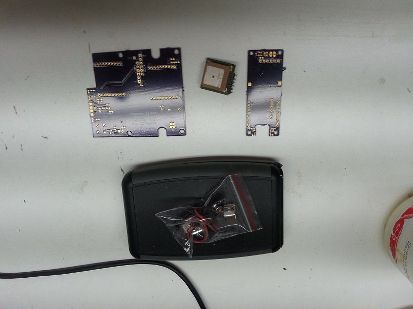
Had some extra parts laying around, so I thought I'd try a MINI
Much to my chagrin, it was NOTHING like the original! :sigh:
This thing is SMALL! I was wondering if anyone else (beside derek) has made one of these?
Anyway, after 4 hours of cussing and swearing, I finally finished. :clap:
Although it has yet to be tested....stay tuned for updates..... please oh please oh please work!
View attachment 185149
I have built one and it was very similar to the full sized version and wasn't that much more difficult.
Just like the original it works perfectly.
The key to all of this is patience and flux.
There are a very few parts that are different but 90% of them are the same.
ok thanks.
just to clarify if I want to just use my pc all I need is a usb to xbee adapter correct? then I can just plug it into my computer and track?
yep. your xbee to usb adapter will still work like the with regular tx.
as far as the parts difference between the regular tx and the mini tx, the gps is different. the mini also has an additional led and resistor to indicate gps lock. I used an orange led but you can use whatever color you like. everything else is the same.
I have built one and it was very similar to the full sized version and wasn't that much more difficult.

how big is the tip on the soldering iron that you used? if it is too big I could see this problem occurring.
my technique is first I use a flux paste and coat the pads of the part I want to solder. next I put a little bit of solder on one pad, hold the part in place with some tweezers and touch the iron to the pad with solder on it. that should tack the part in place wile you solder the other pad(s). then you can go back and touch up the first pad if necessary.
the best way to remove excess solder is solder wick (or braid).
https://www.digikey.com/product-sea...dering-braid-wick-pumps/1311239?k=solder wick
edit:
if solder wick isn't removing the solder, then there is probably copper underneath and there is supposed to be a connection. where is this occurring in the pic?


Here is the face plate in black. I think this is the best color yet:
View attachment 172538
Would anyone actually be interested in purchasing these?
Hi Derek ,
Are you still have those Plate , Please let me know . Thanks
Enrique

What software did you use to collect the flight data and graph it onto the map?
yeah, please share!
Ok I got all the surface mount parts on the mini boards except for the LEDs. Are they polarized and if so how do I know which way to mount them on the board?
Enter your email address to join:
