George, if you're still following this thread: did you calculate the axis offset for the motor in the ET, or did you wing it?
Wow, I taclked that in one of the very long shuttle threads years ago.
Basic thing is, build the WHOLE model, except for the centering rings in the ET, and do not glue the aft dome in. Make up a special disc to temporary go just inside the top of the ET tube, and have a clear plastic window on the inside, with fine markign lines. One solid line for the center axis (left would be the left SRB, right of it woudl be the right SRB). Cross-lines every 1/8" from the center towards the orbiter side. Weigh the ET nose, weigh the recovery system, and weigh the noseweight. Also, pre-cut the outer discs for the future centering rings, weigh them.
Add ALL of that combined mass (of things that will not be on the model when you do this procedure) to the center of this special disc.
Make sure this disc can't slide out from the top, I used some tape along the outer edge of the ET tube, folded inwards.
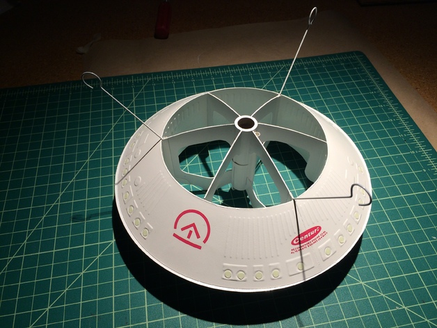
Reason for all of this, is you are going to balance a tire. Well, not a tire, but this method is LIKE balancing a tire. Except you won't be adding weight to one side.
The balancing tool will be a sturdy enough wood dowel, mounted vertically, with a point on the top end. You will place the assembled shuttle (with the special weighted balancing disc in place of the ET nose), to balance on top of that pointed dowel. This is where the clear window comes in, to SEE where the point of the dowel is. You align it so the point stays in the center about the left-right axis. But of course you move the model so the dowel point is somewhere between the middle and the orbiter side. That is what the 1/8" markings are, so you can see how far to go. If it balanced mid-way between a 1/8" mark, then that'll be an extra 1/16" (say between 7/8" and 1", it'd be 15/16"). If it balanced about 1/4 way, then that'd be an extra 1/32".
Now to really judge whether it is balancing level or not, I used a plumb bob method. Taped a scrap piece of 1/8" balsa along the outer top of the ET tube and taped thread to hang down below the ET, with a little blob of clay weighing maybe a gram. I moved the model on the dowel point until the plumb line seemed to be about 1/8" all the way down.
Once you find where that horizontal balance point is, MARK this special disc, and write down on it what the distance is from dead center. Keep this disc for future reference, and also write/type into a file what it is. If at some future time the model mass changed and you had to add "tire weights" to one side to re-balanced the model laterally, then you'd use the old disc again, but this time drill a tiny hole in the balance point and attach a strong thread (like 50-100 pound kevlar) inside of it, so the model could hang by that thread/cord and find out how much mass to add to the non-orbiter side (or towards orbiter side) to re-balance laterally along the pitch axis.
After you've done that, then you can get the Centering Ring discs, mark off and cut the holes for the engine mount tube.
Sort of a PITA , but there's no better way to do it to get it right. That I could think of anyway, without getting into higher-tech or more PITA methods.
The "simpler" brute force way is to ignore it, guesstimate, and most likely the model will pitch nose down or nose up at liftoff due to the imbalance. Which can be solved by adding a crap-load of dead mass to the opposite direction along the ET nose, but as long as the model was already going to be stable enough, then that dead mass hurts performance.
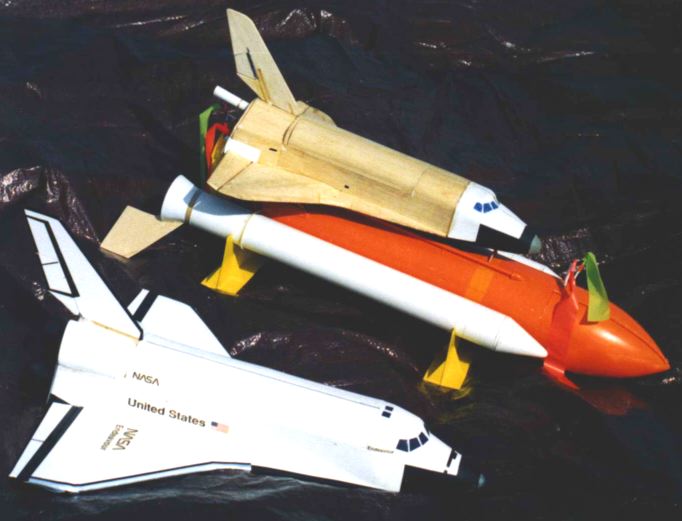
I suspect that many of the old Estes Space Shuttle stack kits that I saw pitch badly at launch were due to the builders building extra-heavy, which messed up the horizontal balance (tire balance) point that the kit was designed for.
And yes, this does mean to really balance it properly, it has to be painted and everything else, too, no significant mass added later, otherwise it has to be compensated for. So, no "mock-up" assembly, doing the above process, THEN painting it! Or adding some heavier R/C gear later, or removing the R/C gear later .
I once did a boilerplate test of a totally new fin system (one single fin on each SRB) using a boilerplate built for when the orbiter had R/C gear in it, but it no longer did. To test fly accurately due to the already-built-in engine mount, I had to add dead mass to the orbiter to simulate what it originally weighed, and using the hanging by a thread method described above to assure the horizontal balance was correct (good thing I still had the original balancing disc and knew the offset distance it was built for)
In theory, Rocksim could do this. In the real world..... no. Just..... no. This is way easier and more certain to be accurate.


")


 [/url
[/url