$30 MPR/HPR launch pad

The Rocketry Forum

Help Support The Rocketry Forum:

This site may earn a commission from merchant affiliate links, including eBay, Amazon, and others.

dixontj93060

Well-Known Member
Joined
Feb 19, 2009
Messages
13,083
Reaction score
45
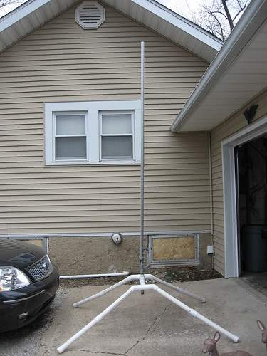
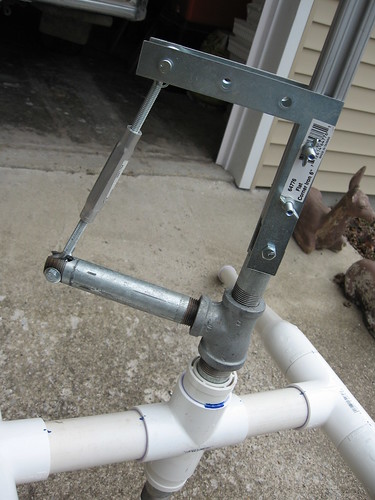
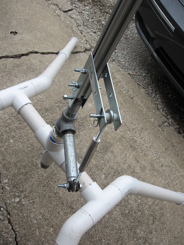
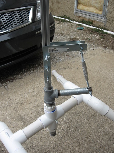
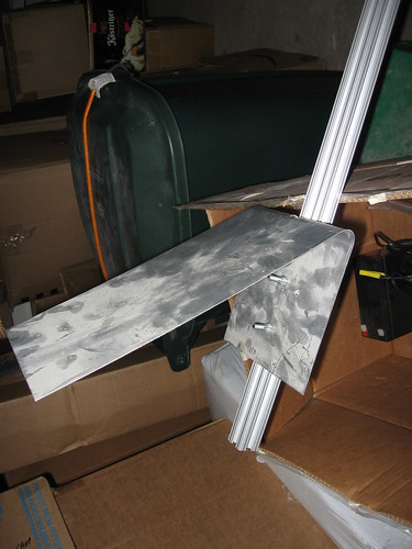
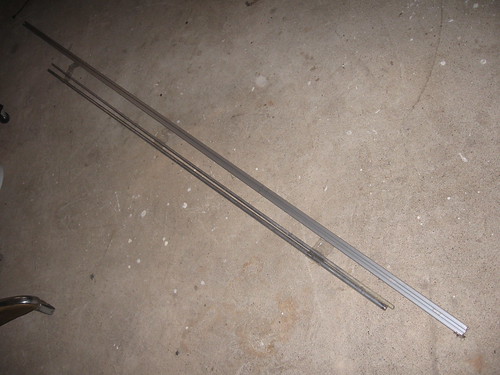
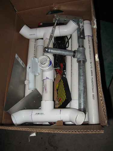
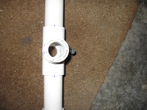
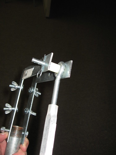
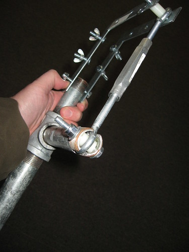
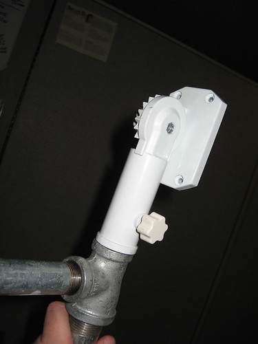
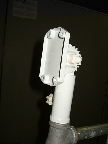
This pad has been in use for nearly three years now, but I never posted its design. I was motivated to do so when I saw a few members contemplating dropping nearly $50 on an adjustable rail bracket. Thus I wanted share this design as an option. I believe it provides a full range of tilt and swivel adjustments that I have seen on much more expensive alternatives. I have used it to launch 4" rockets on J motors. I believe the design, when assembled fully is capable of supporting K motors. Price for the whole pad was a bit over $20 and now, likely adjusted for inflation, still around $30.
 
First a view of the pad with the rail assembly installed. (Note that I quickly pulled the box out of storage and "popped" it together for pictures. There are additional assemblies that are put in place for higher thrust launches.) The base is built with 1-1/2" schedule 40 PVC purchased from Home Depot. You need three 8' pieces.

2340165531_c1f0120b87.jpg
 
Next some critical close up pictures of the adjustable rail assembly taken from a few views, then I'll discuss...

2341000544_70eee3e179.jpg
 
A little higher angle to see the bushing on top of the "L" bracket where you get the angle adjustment.

2340167105_4108ec4aa3.jpg
 
And now the other side where you see the central hub and the set screw that provides full 360 degree swivel of the pad.

2340999126_c8d972e1c6.jpg
 
A couple of details I forgot when assembling the thing quickly this morning. As you can probably see, the blast plate is not there. Simple install (before mounting the rail to the bracket) as shown below:

2340169113_829918b11c.jpg
 
Also the design not only supports a standard 8-foot rail, but with a different assembly put on the main hub (an upside down flag pole holder actually) it also supports a full complement of rods--all Estes, Aerotech, plus the 1/4" and 1/2" 6-foot rods shown:

2340170603_f9e0392a3c.jpg
 
Finally, a big design goal was for the thing to be portable. The whole pad, launch controller, cable (wireless launch control still under development), small rails, blast plate and battery fit into a 23"x15"x9" box (of course, not the 8-foot rail or 6-foot rods):

2340169747_0690ef97d6.jpg
 
A couple of notes on usage before I describe the parts:
  • The legs come apart in the middle for a reason. For LPR flights you only use the lower "foot" piece and the whole pad is much smaller (footprint moves from 6-foot by 8-foot for an HPR configuration to 30"x48" for an LPR configuration).
  • For J flights and above I add two additional braces at the two cross-T's of the central hub assembly to provide more vertical support (A simple PVC piece with T's on top with a half circle cut out of the top of the T)
  • For any adjustment of the rail more than 8 or 10 degrees tilt you need to install the four tent pins (holes in the foot area of the legs to accept) for additional lateral stability.
 
I guess the real key in building this is to get the dimensions of the central hub and metal bracket assembly correct. First the diameter equivalents from this site where you can see that iron pipe O.D.'s are equivalent PVC O.D.'s (I never really knew this). So the swivel section of the central hub can be assembled from two 1-1/2" to 1" PVC bushings on either end of a PVC four-way junction with a 12" galvanized pipe running vertically through the hub area. Looking down into the hub you might see a 1/4"-20 T-nut epoxied into a hole in the side of the PVC cross piece to accept the thumb screw to tighten down on the galvanized pipe when the rail assembly is swiveled to the correct orientation.

2341001098_b1c8fa6ccd.jpg
 
Of course the whole pad can be made beefier by stepping up the PVC to 2" or even 2-1/2" of course at the expense of space and weight. In either case though, I don't think you need more than an 1" vertical pipe. The other reason for keeping this size is that you have to step down to 3/4" pipe for the top vertical and horizontal extensions. The 3/4" pipe dimension is critical as its O.D. is 1.05" the perfect spacing to "sandwich" a standard 1010 rail between two brackets. In the end, this requires an iron T piece that has two of the junctions on right angles of each other to be the 3/4" size while the other side of the T being the larger size. I'm no plumber, but there may be limits to standard pieces that have this reduction ratio.
 
Next the length dimensions (I did the geometry on this when I first designed the assembly, but have since thrown my scribbles away), so I'll just give the results...

The L-brackets are 6" and have 3 holes in each length. As can be seen above, the two inside holes of one leg of the L hold the rail with screw and wing nut assemblies cinched into the 1010 rail on either side. The bottom of that same leg is attached to the top vertical 3/4" pipe with a partially threaded cap screw inserted through the middle of the top threaded area of the 3/4" vertical pipe. This vertical pipe is 3" in length.

The bottom vertical pipe that extends through the PVC hub assembly is 10" in length overall.

The horizontal 3/4" iron pipe is 6" overall and has two slots cut on top/bottom through the threaded area. I simply drilled straight through with a 5/16" bit and used a hack saw to take out the small slots.

Finally the turnbuckle is 5/16"x9 inches. Of course this is the tilt adjustment. This length when fully screwed in gives a tilt well over 20 degrees. At its most extended position the turnbuckle provides for a degree or so beyond vertical. I would expect overall it would be better for this turnbuckle to be an inch or so longer (a bit less tilt, but more stable at the vertical position).
 
Then to hold it all together the outermost holes of the horizontally running bracket leg and the horizontal pipe section use a clevis pin and another partially threaded cap screw respectively. These are run through the center of nylon spacers that act as bushings that are 1" and 5/8", respectively. Of course the clevis pin is provided so you can easily remove the top attachment and let the rail down to an overall horizontal position to easily load your rocket.

Top hinge point at end of L bracket held by clevis pin:

2340426743_83e2202f09.jpg


Bottom hinge point at end of horizontal pipe section held by threaded cap screw:

2341259796_206f61e099.jpg
 
Finally, I did say the pad supported all sizes of rods. At first I was rummaging through the plumbing and hardware sections of Home Depot trying to figure out how I could put together a solid rod brace assembly that also provided up to 20 degree tilt. After a bit of frustration, I strolled past the checkout and saw a flagpole bracket on sale for $2.99. I decided I could easily take advantage of the convenient 1" diameter vertical mount that was already built into the central hub design leading to a convenient mount as below and more than achieve all my adjustment goals.

The bracket area (where the four screw holes are which normally gets mounted on your house) is mounted to two flat brackets situated horizontally top and bottom and sandwiched in between is both the rod and the inner section of the blast deflector (if you look closely you can see the extra four screw holes in the inside back used for rod applications).

Back of rod bracket:

2341285422_950065b80e.jpg


Front of rod bracket:

2340452827_67cd652cf1.jpg
 
I like your adjustment mechanism. It looks a lot sturdier than mine:
<a href="https://micronetsoftware.com/gallery2/v/hobbies/rockets/launchpad/tilt_mechanism.jpg.html"><img src="https://micronetsoftware.com/gallery2/d/278-2/tilt_mechanism.jpg" /></a>
 
Do you have a photo of the rod brackets in place. I am looking at ways to add adjustment to my launch racks.

Sorry, everything is packed up and back in storage.

It is very straightforward though. I just use two straps and a corner bracket. The corner bracket can be found anywhere (see pic attached). Mine is about 3" in the C-dimension. It is mounted between the strap and the back of the blast deflector plate for a "pocket" to set the rod so it has a definite vertical stop.

The straps are just scrap pieces off of a roll of metal strapping. I think it is the type used for securing crates (see pic attached). I actually have three sets. One set bent with a channel for 1/2" rod, one set bent with a channel for a 1/4" rod and one not bent for all other small rods.

It all goes together per the attached .jpg sketch (not to scale).

In all, it isn't too easy to interchange rods, but that isn't really my main use for the pad as I mostly use rail buttons on my designs. But the design is both cheap and effective and sufficient for my needs.

1088a22c1l.gif

19285tp3l.gif

Rod mount.jpg
 
Back
Top