Tubes projecting through conical transitions

The Rocketry Forum

Help Support The Rocketry Forum:

This site may earn a commission from merchant affiliate links, including eBay, Amazon, and others.

hokkyokusei

Well-Known Member
Joined
Apr 16, 2012
Messages
2,908
Reaction score
5
Like the outer tanks on the Saturn 1B?
A while back there was a thread about this, I think. I also think that someone posted a link to some software. I've searched bit can't find it. Anyone remember what I'm talking about?

Cheers
 
Ah, that is what I was looking for, but unfortunately it doesn't do what I remembered. It will draw shrouds for transitions between clusters, but not produce a simple conical shroud with holes for motor mounts to poke through. Thanks for your help though!
 
No, but that's the kind of thing I mean. I know I mentioned the Saturn 1B, but I'm actually working on something else today!
 
Well, that's part of the job (I usually use VCP), but I need to be able to add cut-outs for the motor mounts too. I'm guessing the cut-outs need to be elliptical, but I can't figure out how to draw them by hand. Maybe I'll try trial and error!
 
I'm guessing the cut-outs need to be elliptical

Well, of course it's elliptical! That would be your basic conic section.

You are going to have to do a little basic trigonometry.

Kinda hard to explain here...I'm no math teacher.

Sorry to make you do that during summer vacation...oops...summer "holiday".

I keep forgetting you Brits don't take vacations. You take holidays.

Hope you don't get sick and have to go into the hospital...Oh wait...you don't go "into" the hospital... you go "to" hospital...

Don't ya just love this.

"Americans and Britain...two great nations seperated by a common language. " Quote, Mark Twain.

:D
sandman
 
I'll have to try and work it out. I haven't done any geometry for years!

The holiday/vacation thing used to puzzle me a great deal, but I finally got it worked out. ;)

Sure, we go "to the hospital", but if we're staying we would say someone has gone "into hospital". At least that's what we would say where I live.

Can you imagine my excitement whan a girl in South Carolina came up to me at a party and asked me if I wanted to shag?
 
Originally posted by hokkyokusei
Well, that's part of the job (I usually use VCP), but I need to be able to add cut-outs for the motor mounts too. I'm guessing the cut-outs need to be elliptical, but I can't figure out how to draw them by hand. Maybe I'll try trial and error!


This task was actually pretty well defined in the now lost art of drafting. It is called "developing a surface".

As far as I know, none of the modern CAD packages have this feature. A few specialty programs like our beloved VCP and shroud calculators, and similar programs for the custom motorcycle industry to make templates for cutting frame tubes can make a template for simple tube to tube or tube to cone intersections. There may be something for HVAC ductwork, but I have no knowledge in that area and suspect that any available software may not be free.

You may want to try doing it like the Saturn 1B engineers had to do it; find a book on drafting, also known as engineering drawing or engineering graphics and look up the section on developing a surface. You will need a T-square and a compass and it's rather fun.

Once you have the basics mastered, the Nike-Hercules does not look so daunting. You also have the skills to build unique rockets with square bodies or tubes intersecting in any angle you desire.


Bill
 
Originally posted by sandman
Well, of course it's elliptical! That would be your basic conic section.

You are going to have to do a little basic trigonometry.


Hmmm. I've been doodling and I'm not sure it is elliptical. I think the cut out is elliptical when the assembled shroud is viewed side on, but not when unrolled!
 
You will be dealing with an ellipsoid cross section. It will be part of a 3 dimensional ellipse.

Do this.

Make a test cone (hey it's paper!)

Now do an angled cut in an engine tube that will fit. You will have to carefully trim the minor axis of the ellipse to get it to fit pefectly flush and squar onto the cone.

When it looks satisfactory trace the NEW ellipstical shape onto the cone.

For multiple engine tube you will have to duplicate the cut on the engine tube a number of times.

Is the picture something like you are trying to do?

sandman
 
Yes, that's exactly like what I'm trying to do. Thanks sandman, I'll try that out.
 
Understand this. When you draw the pattern of the cut-out holl you will only be expanding the Minor axis of the ellipse a bit.

Side to side it will get slightly bigger as the cone unwraps but, not top to bottom. that will stay the same.

sandman
 
Yeah, I can see that. I wonder of it would be possible to do this by shining a light through a tube?
 
>When you draw the pattern of the cut-out holl you will only be expanding the Minor axis of the ellipse a bit.

I'm not a hundred percent sure of that. The intersection of a cylinder and a *FLAT* surface is an ellipse, but this isn't a flat surface, it's a cone. The intersection of a cone and a flat surface is an ellipse (it can also be a circle (plane slant angle = 0), which is a special case of the ellipse, a parabola if the plane is oriented "parallel" to the cone (plane slant angle = cone slant angle), or a hyperbola if the plane intersects both the cone and its "mirror image" (plane slant angle > cone slant angle).

So, the projection of the intersection of the cylinder on the cone is an ellipse, but when you "unroll" the cone, the "top" of the ellipse gets "expanded" less than the bottom of the ellipse. Or maybe it's the other way around. Anyway, I wouldn't expect this ti produce an actual ellipse on the flattened surface of the cone.

len.
 
then use a centering ring with holes for the proper configuration slid over the back end to mark the cuts.

one-offs are pretty easy...
if you want more than one, other methods might be more fruitful.

good luck!
 
I'm not a hundred percent sure of that.

I am 100% sure...the resulting hole is an ellipse. Expanding the cone only increases the minor axis.

sandman
 
Thanks for all the help and suggestions guys!

Here's my current plan: because I have 16 holes to mark and cut, I'm going to concentrate on getting a good template first. First I'll print off a shroud with an ordinary ellipse, then offer up a motor mount with an appropriately angles cut. Admitedly the motor mount cut won't be exact and neither will the ellipse, but it will help my "pencil in" the correct shape. I can then produce a template for that shape. Next I'll print out another shroud and mark on it where the 16 motor mounts should go, and draw on the shapes using the template.
 
I'll post pics when there are pics to post ;-)
It's for my rmr descon entry. If I get to finish it in time, this was just one of the problems I've been having with it!
 
sandman sez:

>I am 100% sure...the resulting hole is an ellipse. Expanding the cone only increases the minor axis.

Show me the math.

len.
 
Well, nothing says "relevant" like responding to a thread that is older than my 12yo...

The best answer I could come up with was actually "teardrop shaped".. [edit: with my small temporary issue mentioned at the end of this post, this might not end up being teardrop shaped...]
I had it in my mind to make a conical shroud with four BTs poking through it - something that looked like this:
OpenRocket065.png

I got halfway through figuring it out and realised I was building the wrong thing for the rocket I am working on, but decided to finish figuring out the solution, as it was interesting and I am sure it will come in handy at some stage.

So, the solution I came up with has quite a few steps:
1) use a tool like the shroud calculator on rocketreview.com (https://www.rocketreviews.com/shroudtransistion-calculator.html). You want a tool that gives you the measurements, not one that just spits out the shroud template to print and cut.
2) I am using a combination of methods TVM outlined here:https://www.apogeerockets.com/education/downloads/Newsletter121.pdf that shows how to make an angle cut wrap for a BT
3) In a vector art package, draw the top and side views of your shroud-tube-fest-orama and take one of the BTs that will disect the transition and divide it into 32 segments:
Affinity Designer011.png
4) follow the steps in the TVM paper to create a wrap template for a straight cut on the inner tube on the right hand side:
Affinity Designer012.jpg

[Finishing]...

5) Now you have the curve profile for the side of the diagonal "cut" in the BT, we can transpose it to the front facing side of the transition.
6) Divide the top circle the same way as the right one and extend vertically. Where the lines meet their equivalent horizontal from the wrap profile:
Affinity Designer014.jpg we drop a point and draw the line (then mirror for the left hand side to make the oval shape)

Affinity Designer015.png

7) Now we slice up the large circle into 60 slices of 6deg and extend the lines that cross the oval upwards to plot the oval's points
Affinity Designer017.png

8) we can now create measuring lines (red and blue) to each of the points from the bottom of the transition:
Affinity Designer018.png

9) Draw your shroud per the measurements provided by the tool and divide the shroud into 60 segments (just like the large circle) the dark segment drawn is the beginning of the overlap on mine:
Affinity Designer019.jpg
10) Translate (without changing their length) the red and blue measuring lines onto the shroud segment lines:
Affinity Designer020.jpg
11) draw the curve that follows the points (and mirror) and you have your first shroud hole..
Affinity Designer021.png

12) then evenly copy/rotate (be sure to set the centre of rotation for the hole curve to be the center point of the shroud) 3 more of the shroud holes evenly. My shroud has a 152deg arc, so 152/4= 38deg

13) and voila! (10 pic limit - continued in the next post)
 
Last edited:
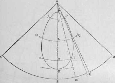
Fig-517-Half-Pattern-of-Cone-Shown-in-Fig-516.jpg


https://chestofbooks.com/crafts/met...rsected-By-A-Cylinder-Of-Less-Diameter-T.html
 

That's where I am heading.. I just made a transposition error in my diagram that I need to fix, and I will finish the write up... The doc you posted is useful - thanks.. (I just wish the diagrams were better resolution... :^( )
13) and voila!
Affinity Designer022.png

Given this shroud has such a thin lower edge on the large diameter, if I was actually building this, I would extend the shroud about a cm then cut, roll, glue, fit, then TRIM / SAND the excess back once it was glued in place.. I would probably also make a shroud with no holes to use as a form for this one while rolling/gluing it...


Affinity Designer023.jpg

So while the method is not new, this is a little easier to do in a good vector based art program. I use Affinity Designer on the mac ($79AUD) but the free, open source InkScape could do it all. I used to use inkscape exclusively, but decided that the amount of time I spent in vector art programs justified me spending $80 of my own money for an app that was a little more powerful and user friendly...

I hope people find this useful...
 
Last edited:
I wrote a Perl script back when I was building the APRO Lander II to do something similar. There my goal was precise cuts for a launch lug poking through conical shrouds. Almost but not quite the same thing. Maybe I'll update it to do this as well. I may need something like it someday.

On the other hand, this would be a good Inkscape exercise. I could use the practice...
 
I've done this too, but I had to do it the easy way. I figured there was some kind of math that I didn't know how to do, and LW helped me with a formula to mark printed shrouds where the holes should be, but that was somewhat difficult also. So I opted to assemble the shroud I needed, CA'd it thoroughly and taped it to the rocket instead of gluing it. I had 3 outer lines drawn on the tube above the shroud where my outer tubes were going to be. I placed a tube on the line butted up to the shroud and made centered tic marks on the shroud for all 3 tubes. Using line of sight, I was able to carve out most of the hole and sanded the edges until I got the fit I was looking for. Here are two different examples.

DSCF2150.JPG DSCF2223.JPG
 
Only 14 years too late, but a cone intersecting a plane forms an ellipse, not a cylinder intersecting a cone.
 
Last edited:
Back
Top