[Progress] Minimum Diameter 54 (CTI L935)

The Rocketry Forum

Help Support The Rocketry Forum:

This site may earn a commission from merchant affiliate links, including eBay, Amazon, and others.

A5tr0 An0n

Well-Known Member
Joined
Sep 29, 2012
Messages
521
Reaction score
10
Introduction:
In my recent attempt to start posting more, here is another build thread on a vehicle that has already been built… well mostly built. It has not been painted or flown on the motor it was built for. Nonetheless the name of this vehicle is Progress. The reasoning for this is that when I started building it I had two thoughts (if you will) in mind. One was to "progress my MD building skills," and the other was well… thats a secret that will be reviled in another one of my threads very shortly. ;) Okay enough blabbering, lets move onto the build.

Design:

Thoughts:

I knew I wanted to have a 54mm MD rocket and after playing around with OpenRocket I knew roughly what the design would be like. Basically I wanted to have hardly any space inside, to the point that recovery may not fit and I wanted to launch it on the L935… this I knew. I tend to build or in this case buy/modify rockets based on a motor I want to launch. I was getting ready to start buying all the parts and then viola! Madcow released their Tomach kit and it looked very similar to what I wanted, so to say the least I was interested. I played around with the kit in OpenRocket and that lead me to believe it would be fairly easy to modify it to meet my expectations. So the next thing I did was look at the price (which turned out to be the biggest motivating factor), it was priced I believe around $120 - $130 (introduction price) when I bought it. In comparison, to source the parts individually, just the airframe and nose cone would have cost me almost $100, so I jumped on the Tomach deal. So in conclusion, for a little bit more I got a little bit more. Now I have extra parts laying around, which IMO is never a bad thing.

Technical Specifications:

1. Nose Cone: ~6.1:1 Haack Series filament wound fiberglass with an Aluminum tip. The cone metrics are as follows: a base diameter of 2.205" (OD), a length of 13", a wall thickness of 0.079". The shoulder metrics are as follows: a diameter of 2.126", a length of 3.25", a wall thickness of 0.079". The installed shoulder extends past the nose cone at a length of 2.125", this is the amount of shoulder that will couple with the airframe. This results in a combined length of 15.125" and a total mass of 0.536lbs.

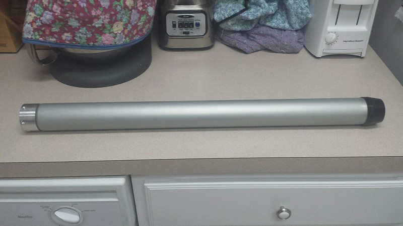
2. Airframe: Standard G12 filament wound fiberglass (natural). The airframe metrics are measured at 2.205" in diameter (OD), 36" in length but has since been cut down to 34.5" in length, 0.079" in wall thickness, and 1.25lbs in mass.

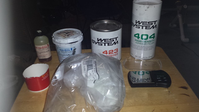
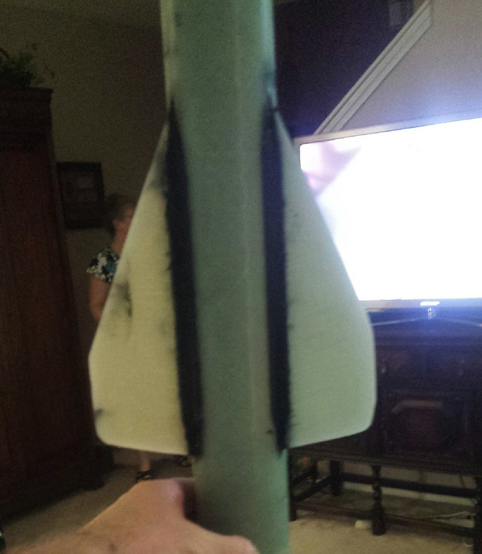
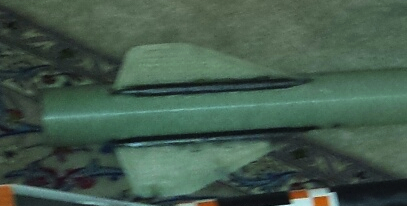
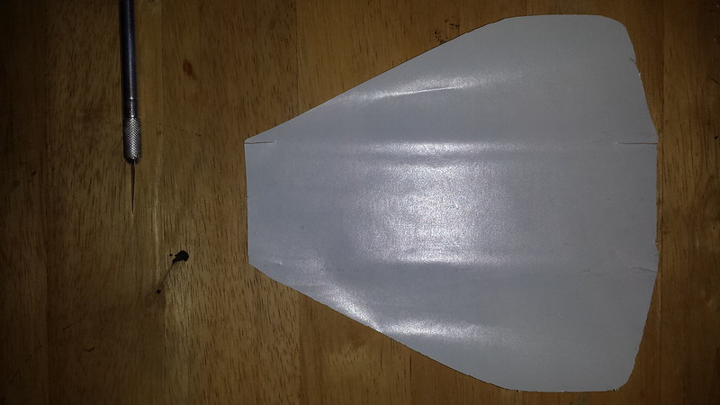
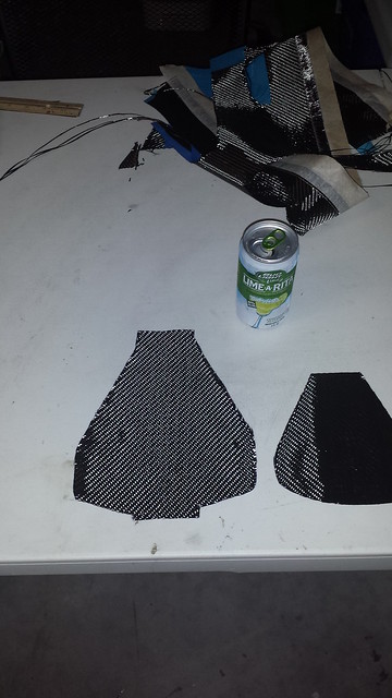
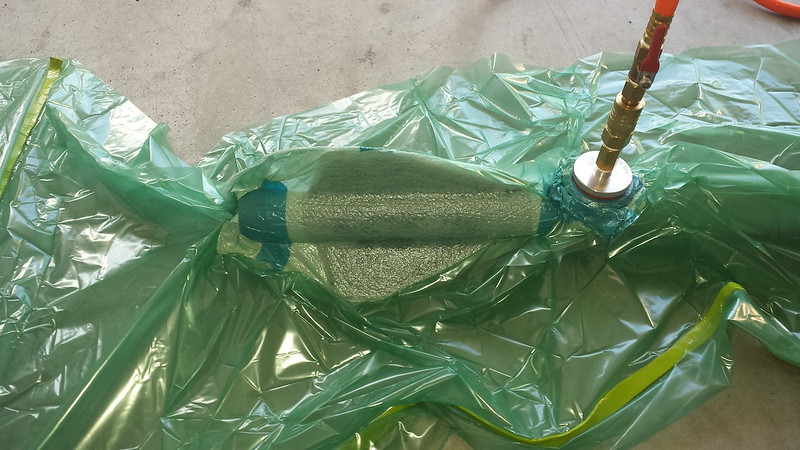
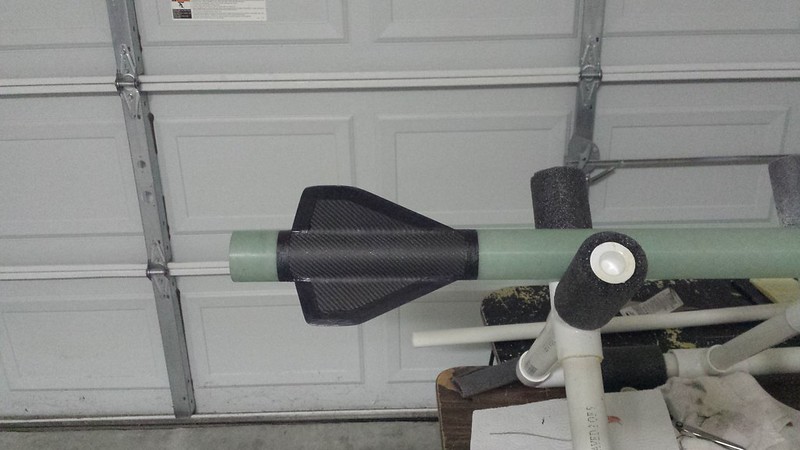
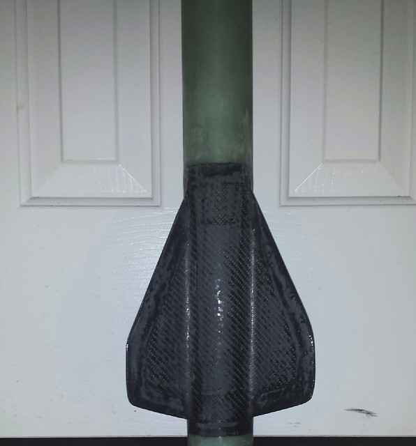
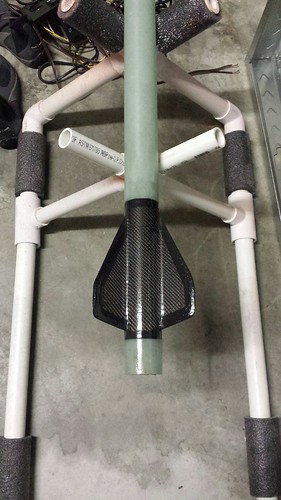
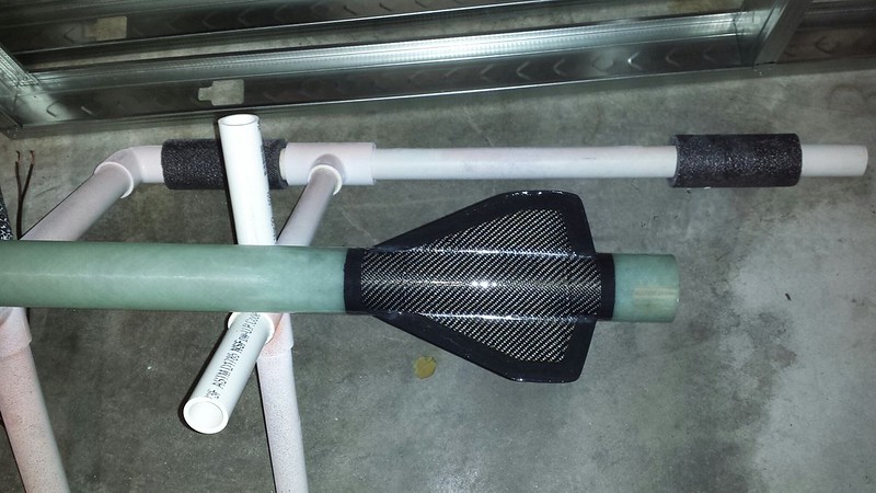
3. Fins: The fins used are the fins that come with the Tomach kit and thus is a three fin design. They are made from G10 fiberglass plate (natural) and the metrics of the unreinforced fins are measured as 7.63" root cord, ~2" tip cord, 2.366" span, 0.125" in thickness and a combined mass of 0.32lbs. However I have not left them unreinforced and did not leave them stock. For the modification I added a 0.25" bevel around the entire fin (leading/trailing edge and tip cord area). In regards to the reinforcement I added 2 layers of 3K 2x2 TW 270GSM (high density) aerospace grade carbon fiber in a tip-to-tip fashion (up to the edge of the bevel). The first layer stopped about ~1" from the edge of the fin where the second layer went up to the edge of the bevel (or 0.25" from the edge of the fin). I did this to allow for a thinner and smoother transition. With the tip-to-tip carbon fiber the metrics have slightly changed and and have resulted in measurements of 0.175" thickness (thickest place) and a mass of 0.41lbs.

4. Boattail: The boattail gives me greater aerodynamic properties, reduces stability and therefore ultimately gives me greater performance (altitude). So I chose to go with the CTI Pro54-TC, this also acts as a motor retainer/thrust plate and is flush with the airframe. It is made out of Aluminum 6061 and the metrics are measured at 2.2" in diameter (fore), 1.9" in diameter (aft), 1.42" in length, 0.16" in wall thickness, and a mass of 0.128lbs.

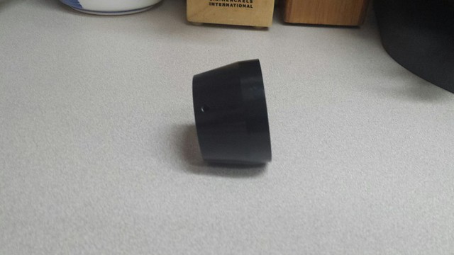
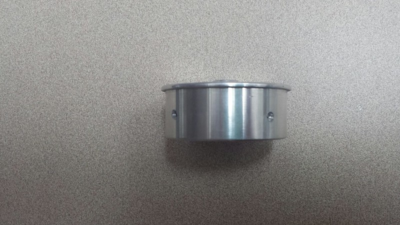
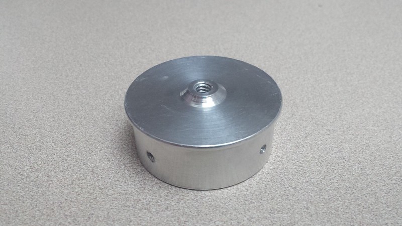
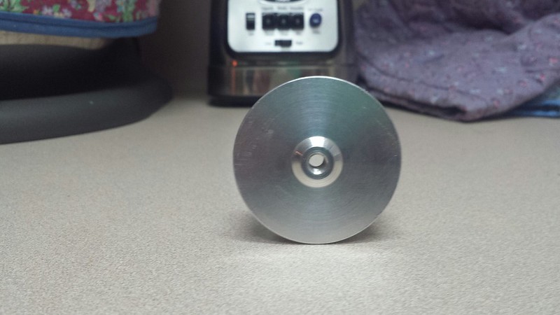
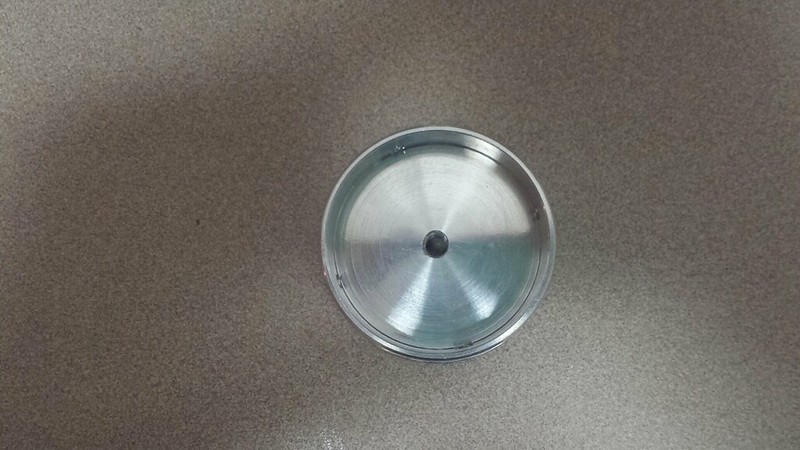
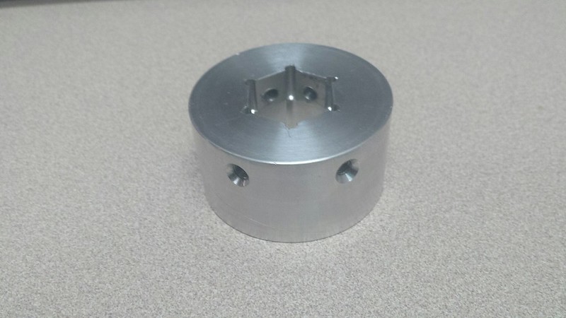
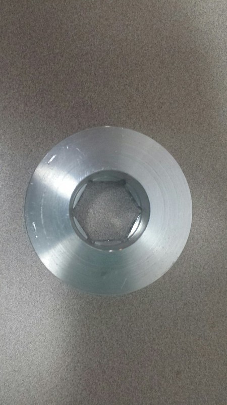
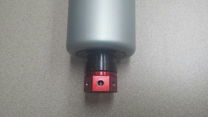
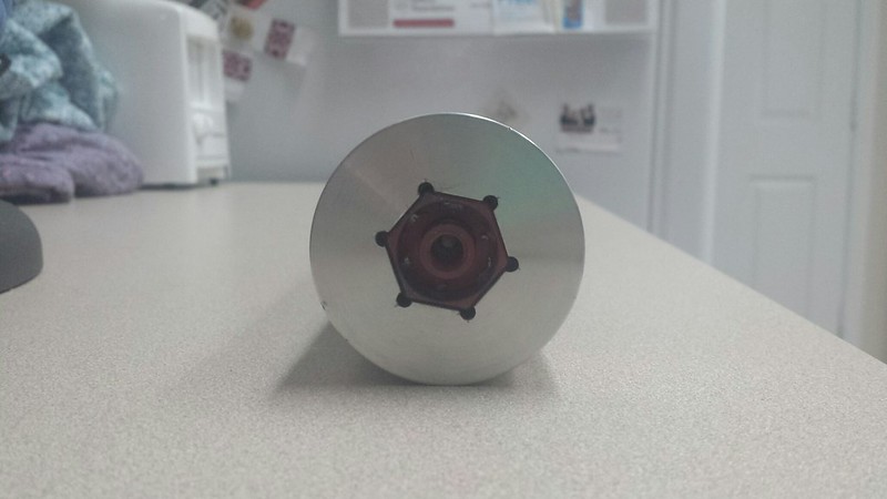
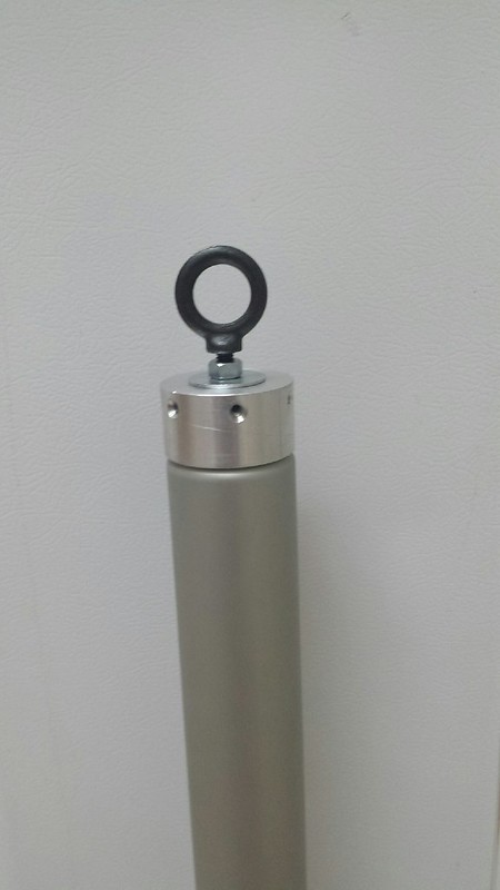
5. Motor Retention: Seeing as this is a minimum diameter bird their is no MMT inside. So that left me with 3 easy accessible options: friction fitting (uneasy about it), Aeropack minimum diameter retainer ( more than needed and less than ideal), and to make my own forward retainer (easy). I am not to keen on friction fitting the motor inside the airframe and seeing as this vehicle is also going to be used for another purpose this option is not possible. So that left me with two options. The Aeropack retainers are nice but they are big and bulky and take up too much needed space, so therefore I opted out of using one… even though I had a left over 54mm MD retainer sitting on the table. So my last option was to design and machine one myself and that is the path I choose. More details to come later in the thread but it is basically a scaled up version of the one I built for ODIN.

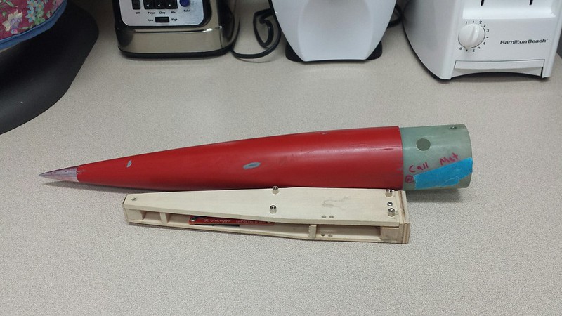
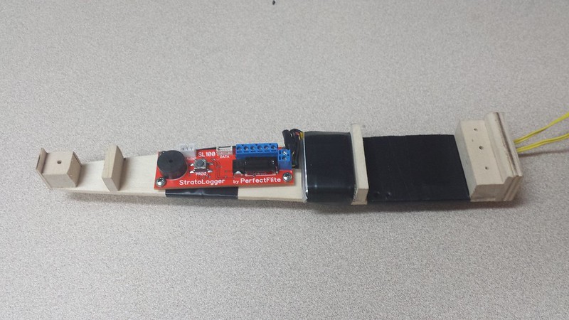
6. Electronics/Recovery: The electronic/payload bay is located inside the nose cone, this being due to the fact that there is no room inside the airframe and why not use the empty space inside the nose cone? It just makes sense. The used flight computers/GPS systems/cameras are the TeleMega, Aim Xtra, GoPro 3 (black), and a 808 #20 (keychain camera). This gives me redundant tracking, redundant flight computers, a view of the flight (onboard) and a view of the recovery deployment/descent. Recovery is a 36" toroidal main parachute, yielding a Cd of 2.2 and thus should result in a descent rate of ~20ft/s. As a note, I normally like to bring them down fast but for the mass this parachute has a tight packing volume that is needed. There is no drogue parachute per se, the drogue is the deflated main that is tied together and released to fully inflate at 1500ft. The used harness is the 1500# 1/4" kevlar braided cord at 20ft in length. Since this is not a zipperless design the harness length should help prevent a zipper in addition to the material that is used.

7. Launch Approach: Naturally this will not be rod/rail launched. For the ODIN rocket I built a tower that is 6ft. long and adjustable to fit multiple rockets, therefore I will be using the same tower for this vehicle. I did some quick calculations and I estimated that if launch buttons were used it would take off ~1500ft from apogee. Not too drastic per se, but something about rail buttons on a minimum diameter rocket just does not add up. The maximum tower departure velocity is 111ft/sec.


14466644154_1aa3da9c5b_b.jpg

Mostly designed in OpenRocket, however was cross checked in RASAero and RockSim.


14488857633_e4398cb5b8_b.jpg

3 dimensional representation of the internals.


14275596510_d8b3fda9ea_b.jpg

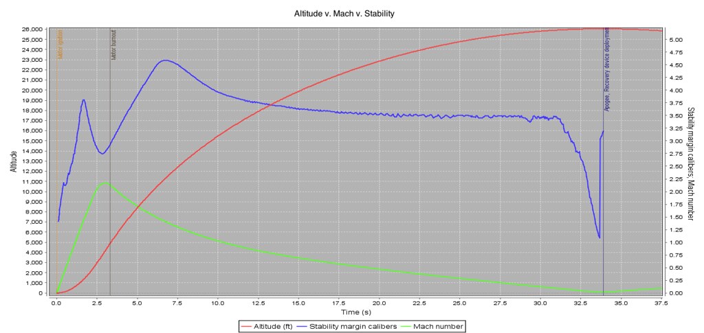
It is what it is. Not 100% as built sim; that will come later. The dramatic CP/CG shift due to higher Mach flights starts to occur when the vehicle is around ~M1.625 and drops ~1 caliber in stability. This vehicles stability never drops below 1 caliber at any point in the flight. I feel that gives me enough insurance on stability.


Conclusion:
That about sums it up. If you have any questions or concerns then let me know. All the pictures/data will be posted shortly. Stay Tuned.


***Disclaimer:***
Here goes the usual disclaimer. Keep in mind when commenting that this is a build thread of a build that has already mostly happened and started almost a year ago. The construction techniques used may have been changed and/or modified since the time of this build. I am in no way telling you that these are the best or even right methods for constructing a rocket but rather the methods that I used at the time. Also this is a minimum diameter rocket but do not mistake that, for it being optimized.


Mat
 
Last edited:
Following this. I'm definitely interested in that tailcone end closure; I didn't know those existed. Is there anything like that on the AT side of the field, especially in 38mm?
 
Following this. I'm definitely interested in that tailcone end closure; I didn't know those existed. Is there anything like that on the AT side of the field, especially in 38mm?

Not in 38mm, it failed to be certified. There is in 54, though.
 
Do you know what the causes of failure were?

I heard that it caused vectored thrust with some smaller nozzles. The 38mm nozzles are alike enough that it's unlikely they could trust consumers to be able to tell the difference, unlike in 54mm where any single-throat nozzle works.

Also, it was really thick and heavy, hurting stability.
 
I heard that it caused vectored thrust with some smaller nozzles. The 38mm nozzles are alike enough that it's unlikely they could trust consumers to be able to tell the difference, unlike in 54mm where any single-throat nozzle works.

Also, it was really thick and heavy, hurting stability.

Well that is good to know, learn something new everyday. I had no idea they ever tried it out for the 38mm sized motors.
 
Well that is good to know, learn something new everyday. I had no idea they ever tried it out for the 38mm sized motors.

I made my own tailcone (much thinner and lighter, only 9 grams) which I had planned to use for my I altitude attempt, but I was discouraged from it by the TAP who witnessed my flight, who relayed that anecdote to me.

13+-+1


It used 3 setscrews to clamp into the inside of the aft closure.
 
So apparently I do not have as many photos as I thought I did. Basically I have epoxied in the nose cone shoulder into the nose cone with JB Weld, beveled the fins, tacked on the fins with JB Weld, and also applied the filled fillets. For the fillets I used Cotronics 4525 filled with glass, graphite and west systems 404.

The methods I used in this build were essentially the same as with my other builds… except this is the method in its infancy. I used an earlier method that much resembles the method used in the ODIN build that can be seen here --> Click Here To see Like Construction. It was one of my earlier attempts and it did not come out to bad.


14385408532_1e3bfbfa08_z.jpg

Ready for mixing and bonding.

14283551370_e2c9b561d7_c.jpg

Above you can see the rockets Gods hovering my build. You can also see the nose cone, airframe, and fins with fillets.

14490312573_afcbd6611d_c.jpg

It is hard to see but this was one of my first attempts to try aerodynamic fillets with Cotronics 4525 (not easy to work with). Note that I also made a mess… I thought oh well I will just wipe it off… wrong!

14283547749_b74c572aac_o.jpg

Here you can see the aerodynamic fillets and the bevel.


More to come soon. Stay Tuned.


Mat
 
Last edited:
I made my own tailcone (much thinner and lighter, only 9 grams) which I had planned to use for my I altitude attempt, but I was discouraged from it by the TAP who witnessed my flight, who relayed that anecdote to me.


It used 3 setscrews to clamp into the inside of the aft closure.

6061? Very nice work indeed. That is very light… Mine is for a 54mm but still comes in at 58.1g. What is your wall thickness on that one?

Mat
 
6061? Very nice work indeed. That is very light… Mine is for a 54mm but still comes in at 58.1g. What is your wall thickness on that one?

Mat

It was something like 0.05 inches, except for the part the setscrews go through.
 
I don't have many photos of the tip-to-tip process either.

Here goes a quick recap of the process, which is outlined in more detail here --> Click Here To See A Like Method.

First I prepare the surface for bonding. Same method as the ODIN rocket except I drilled small holes along the root cord for epoxy to go through.
Next comes laying down the Con-Tact adhesive shelf liner on the fin area (make sure to clean before applying the "sticker.")
Then I cut out the needed shape. In this case I did so twice for each fin set. The first layer I cut to lay 1" from the fins edge and the second layer I cut to lay 0.25" from the fins edge. I did this to have a thinner transition and to retain the bevel.
I used Cotronics 4461 laminating epoxy for the tip-to tip. This epoxy is rated to 500F with a post cure. That will be more than needed for this flight profile.
I also take extra steps to prevent delamination; to do this I apply Cotronics 4525 to the edges of the fins covering the lay up. The 4525 is rated to 500F with a post cure also. In this case I applied the 4525 0.75" from the edges of the fins.
After everything is cured, of course, I sand and sand and then wipe on wipe off more laminating epoxy until I have a even smooth surface.
The only other thing that I do is rough it up again in preparation for the paint… yes that is right, I paint my Carbon fiber!

14447339186_5e84845394_c.jpg

Con-Tact adhesive shelf liner cut out to the fin shape.

14287266079_d178e44ba8_z.jpg

Cloth cut. Left: 2nd layer and Right: 1st layer.

14473188612_2ea91261af_c.jpg

Vacuum bagging the fins.

14466998081_ce8f566ea4_c.jpg

Tip-to-Tip all finished and the 4525 is laid down and cured. Sanding 4525 just blatantly sucks.

14287375198_7888e32277_z.jpg

Sanded and then wipe on wipe off process initiated.

14447257526_d89faf0e88.jpg

Almost there...

14283744560_333204861b_c.jpg

Wipe on wipe off process finished.


This is all pretty simple; if you would like more details click the hyperlink in the second paragraph. More to be posted in a bit. Stay tuned.


Mat
 
Last edited:
It was something like 0.05 inches, except for the part the setscrews go through.

That is pretty thin. Mines 0.16" thick… yeah. It helps get my stability down on this rocket so no worries.
 
Last edited:
Hmm, I'd never considered set-screwing to the inside of the closure... good idea. CarVac, any chance you have the engineering drawing from that around? I don't seem to recall them from the Disappearing Act thread.

Is it known why it causes thrust vectoring? I could definitely take the "just try it out" approach at one of our non-public launches, on a durable rocket and a far pad.

A5tr0 An0n, looking really good, especially the tip-to-tip. You say you want to get the stability down, are you overstable? Margin of stability looks rather near 1cal at launch.

I winged that one. I just went at it on a manual lathe, so there is no drawing, unfortunately. The thrust vectoring was probably due to the exhaust plume coming too near to the lip of the tailcone on one side during a momentary instability, and then staying asymmetrical as a result. Or something of the sort.

A5tr0 An0n: seriously, don't reduce your stability. It will come back to bite you in the butt.
 
re 38 mm tailcone problem- The nozzle for 38 mm AT motors are relatively short and don't extend much beyond the end of the motor with a standard closure. With the tailcone closure the nozzle is recessed a good bit. I thought the problem was due to the krushnic effect, but it could be the exhaust plume impinged on the tailcone. Same reason a tailcone closure can't be used on 54 and 75 mm AT motors with medusa nozzles.
 
re 38 mm tailcone problem- The nozzle for 38 mm AT motors are relatively short and don't extend much beyond the end of the motor with a standard closure. With the tailcone closure the nozzle is recessed a good bit. I thought the problem was due to the krushnic effect, but it could be the exhaust plume impinged on the tailcone. Same reason a tailcone closure can't be used on 54 and 75 mm AT motors with medusa nozzles.

I have strong doubts about the applicability of the Krushnic effect in HPR. The motors produce so much more gas, and they don't sit flat on deflector plates. Thus the gases don't accelerate through the venturi formed at the gap between the body tube and the nonexistent flat deflector plate. It is an effect limited to model rockets like the Estes Saturn V with its single motor recessed deep into the base, such that the exhaust probably slows significantly before leaving the bottom.
 
I have strong doubts about the applicability of the Krushnic effect in HPR. The motors produce so much more gas, and they don't sit flat on deflector plates. Thus the gases don't accelerate through the venturi formed at the gap between the body tube and the nonexistent flat deflector plate. It is an effect limited to model rockets like the Estes Saturn V with its single motor recessed deep into the base, such that the exhaust probably slows significantly before leaving the bottom.

Yes, you are probably right.
 
I have strong doubts about the applicability of the Krushnic effect in HPR.

I tested out a nozzle shroud for our Galaxy and California Kid rockets where the motor was recessed deep into the shroud. The effect was quite pronounced. Would have looked great with a sparky. It made the shroud single use though.

I agree that the tail cone vectored thrust problem was probably due to the flow adhering to one side of the tail cone.
 
UPDATES:
I added some more pictures that I found to post numbers 9 & 12.
 
Last edited:
A5tr0 An0n, looking really good, especially the tip-to-tip. You say you want to get the stability down, are you overstable? Margin of stability looks rather near 1cal at launch.

I winged that one. I just went at it on a manual lathe, so there is no drawing, unfortunately. The thrust vectoring was probably due to the exhaust plume coming too near to the lip of the tailcone on one side during a momentary instability, and then staying asymmetrical as a result. Or something of the sort.

A5tr0 An0n: seriously, don't reduce your stability. It will come back to bite you in the butt.

The vehicle is almost .5 calibers over stable when the boattail is not installed (assuming over stability being 2+ calibers). I tend to have slightly windy launches and want the ability to still launch without severe weather cocking.

The lower stability caused by the boat tail is not a problem with this rockets flight profile. I built this to only achieve a handful of flights on specific motors and with its current stability on all desired motors it is never below 1.99 - 2.13 calibers (with the boattail). Now say if a put in a 4 or 5 grain then it will drop down around 1.8 calibers which is still fine. However I, in the forceable future will not be launching this on any motor smaller than a 6GXL or a 2550. I always look at weather conditions and run sims before each launch. I have done this in the past and with similar profiles with no issues, I don't foresee any problems with it. Now on my 98mm MD… that is another story and I will not have the issue of a boattail there… I did look into it and opted out of one.
 
Last edited:
A little more information and photographs about the boattail.

I chose to go with a boattail mainly for performance reasons. Ultimately it reduces base Cd and therefore the overall Cd as compared to not having one. I was also concerned at the time that CTI's normal aft closure might stick out past the diameter of the airframe slightly, where as the boattail would allow a more flush and smooth transition. As mentioned in above posts when using a boattail it adds aft weight to the vehicle and thus reduces stability, especially when it is made of a more heavy material such as metal. However for all planned flights this rockets stability never reaches a point of concern at any point in time during the proposed flights.

You can read the measurements in the original post in item number 4 under the technical specifications and look at the below supplied drawing. As far as performance goes for the chosen motor it results in ~1600ft of altitude gain when using the boattail.


14469600774_502934ea93.jpg

CTI 54mm boattail drawing.


14472712424_b35cde9097_z.jpg

Side shot of the 54mm boattail.


14472712224_fd5d9694f9_z.jpg

Bottom view of the 54mm boattail.


14450802436_c05864df4c_z.jpg

Top view of the 54mm boattail.


14490997343_74ed1574b9.jpg

Installed on the aft end of the motor casing and thus acting as aft closure.


14472715604_a570ecea03_z.jpg

Mock up of how it will look, more or less.

Will update with a picture of it installed with a motor later this evening.


Mat
 
Last edited:
All of the electronics are housed in the nose cone therefore and I need a bulkhead. Now this vehicle is designed for two purposes and the later will need just a little extra forward mass and a Aluminum bulkhead does just that. I chose 6061 T6 as the material and think it is an all around good choice for this application. The electronics sled will be bolted directly to the bulkhead and the bulkhead will be bolted to the shoulder.


14295207708_0bf7a4cd15_c.jpg

CAD drawings. I had to shrink them down to fit it all onto one page and it has distorted the quality a bit.


There are a few changes from the CAD designs and the finished product, mainly to make it a little more structurally sound around the eyebolt connection.
14480872194_c63df83837_c.jpg
14458988186_2d2091d9d9_c.jpg

14482081995_aed48e3a99_c.jpg
14458988886_51f1441384_c.jpg
14295462830_26e539133d_c.jpg

Various sides and shots.


14295493088_e30255dc5d_c.jpg

Assembly shot. Note the non forged eyebolt is for show only.

14295493678_0350059c6c_c.jpg

Assembly shot number two. Note the non forged eyebolt is for show only.

Final mass came in at 0.168lbs and the metrics are also pretty close and down the line to the CAD.

Mat
 
Last edited:
Since I have decided not to friction fit the motor I needed a new solution. Seeing as the Aeropack minimum diameter retainers take up more space than I am comfortable with and that they are non removable (epoxied in place), I chose against using one on this go around. I needed a different solution so I sought out to make my own. Since I have made a minimum diameter retainer already for the ODIN rocket (albeit 38mm in size), I just basically scaled it up for the 54mm size. The metal of choice is Aluminum 6061 T6, it is fairly strong, lightweight, and easy enough to work with and I have had good results with it in the past.

Now I might as go ahead and mention why I chose this option instead of the Aeropack retainer in a little more detail. First, this rocket is dual deploy out of a single airframe so space is at premium. That means that the Aeropack retainer is a little longer than desired. Second, this is a single stage rocket but I have plans for it to be a 2 stager (maybe you already noticed in some of the pictures). Nonetheless since this is a minimum diameter rocket I needed a way to light the sustainer after a long coast (so no help from the booster). I use Taperwire to send electricity to the igniter; this is not head end ignition and thus the wire has to run from the top of the vehicle to the bottom and then be inserted into the motor and ran back up top. Due to this reason I need my motor retainer to be removable, to allow replacement of the Taperwire. The Aeropack retainer has to be epoxied into place and therefore is not removable and ultimately these are the two reasons that lead me down this path. I do however use the CTI Delay Closure Adapter to screw into the top well so that an eyebolt may be inserted into the motor/case assembly.


I did some quick drawings of the part and I hope to have it finished within a week or 2 at most. I am estimating a mass of around 0.32lbs. Once this is done I can drill the holes and paint the rocket and all will be done.
14481014511_ec8f3eba1f_c.jpg

I forgot to add the motor for reference in the drawings. However the way this works is that this piece is mounted on top of the delay closure adapter and then a eyebolt and washer are placed/screwed into the adapter and this locks the two pieces together. Next the newly found assembly is inserted into the airframe and then countersunk screws are used to hold this all in place. This keeps the motor from falling out the aft end of the vehicle and also acts as a thrust plate at the top and prevents the motor from moving + vertically in the airframe.


I am hoping to knock out this part in a week or two, so photos to come soon. Then on to the painting and all done.


Mat
 
I have let this thread slip a bit also. Time willing, I will try and finish this thread up.

Okay so all the machining, drilling, taping, etc. is done and here is the motor retainer. As you can see it is a scaled up version of the one I did for the ODIN rocket. I had to make a few adjustments to the retainer to fit the ejection/plug well on the CTI motors. Basically the retainer is half hex (to fit over the AeroPack adapter) and half circle (to fit over the ejection/plug well). I drilled through the AeroPack adapter and taped the holes for 10-32 bolts. I am using six 10-32 bolts to retain the retainer into the airframe. The bolts are centered with the center of each side of the hex and do go through the AeroPack adapter.

This retainer functions the same way as the ODIN retainer does and you can find more details on the ODIN Thread or here in post #25.


14476656130_756e3b3fa3_c.jpg

14661066574_e4592fae1f_c.jpg

14683227143_ccc6e1e038_c.jpg

Various shots of the retainer. Instead of making a perfect hex on this one, I found it easier to just drill the corners giving them all a slight radii. The adapter fits pretty snug.


14662967532_b2840739e4_c.jpg

Adapter is installed onto the motor. Here you can see the transition from a hex to a circle.

14660113231_b795d09860_c.jpg

Motor retainer is slid over the adapter and rests on most of the motor/casing (some of the casing is pressed). The overall fit is exactly what I was looking for.

14683225353_ecf0098910_c.jpg

Side shot of the almost complete motor assembly.

14476700478_ac1d94bdf8_c.jpg

This assembly slides into the airframe and is retained via six 10-32 bolts. The eyebolt allows the recovery harness to be attached to the forward end of the motor assembly and the nut/washer/eyebolt combination prevents the motor from falling out of the aft end of the vehicle.


14476693249_828bb90280_c.jpg

Top shot showing the motor assembly inside the airframe.

14660110061_8da32bba89_c.jpg

Countersunk holes for the bolts.

14476652850_b9ed376274_c.jpg

All assembled and bolted into place. It is pretty much flush with the airframe. I had to grind the bolts down just a bit to get them flush with the tube.


This setup seems to be very firm and there is no vertical/horizontal play. I have tried to simulate rough conditions with it tethered to a harness and it held its ground. All in all I am happy with this configuration. If you have any questions then let me know. Next will be the electronics area, painting, recovery testing, launching platform, and launch. Stay tuned.


Mat
 
Okay so this thread has been forgotten about. Time to bring it back to life and then put it to sleep! This post will be about my electrical configuration and recovery.

Seeing as I lost my TeleMega before this flight I had to adjust the sled for different electronics. In this flight I used the Aim XTRA, SL100, and 808 #20 video camera. All electronics are housed in the nose cone of the vehicle and utilize the camera hole as the vent hole for the barometers. In case your worried about the pressure generated by mach on the ascent, the AIM XTRA has been set to ignore the barometric pressure on ascent and the SL100 has a soft Mach lockout. Now my sled concept is the same as what I did for the ODIN vehicle, basically a tapered sled to conform to the nose cone and utilize this as a way to prevent any fore vertical and horizontal movement. The camera and bulkhead prevent any aft vertical movement.

Instead of using the 36" toroidal parachute I went with a 24" classical elliptic parachute, mostly because it would work and I already had one. This parachute has a Cd of roughly 1.5 and therefore should bring the 6lb. "burnout mass," rocket (rounded up for conservatism) down at ~33.45ft/s. The means of deployment are your standard apogee charge, which then pops the nose cone off, thus pulling out the main parachute at apogee. The main parachute (and only parachute) is zip tied shut and released via the cable cutters at 1500ft during the descent. Two independent cable cutters operated by two separate flight computers are being used for redundancy.


Disclaimer: Please note that I did not take photographs of the electronics and sled before the flight. Therefore all these photos are post flight photos and may not be setup or shown how they might look before the flight.


14712168578_a91f382781_c.jpg

Tapered electronics sled conforming to the nose cones curves for secure placement.

14854870605_f057c6eb9e_c.jpg

To fit the new electronics into the nose cone I essentially made a double decker sled, with bulkheads and electrical tape holding the batteries in place.

14852424874_4484912af7_c.jpg

Two story sled with AIM XTRA on top and the SL100 in the middle.

14852424674_54cc6f52dc_c.jpg

Side shot.

14668197770_eb19600805_c.jpg

Side shot #2. Here you can see that the SL100's battery is located directly behind itself and is secured via the bulkhead and electrical tape.

14712227247_0af851dce0_c.jpg

Bottom shot. This is where the AIM XTRA's battery is located and secured via electrical tape and a bolted angle bracket.


Mat
 
Man I'm so jealous. The AIM XTRA 2.0 has got real slim. I really need to get it for my Mariah 54. By the way the AIM XTRA uses all the sensors to avoid the possibility of being fooled it has gone past apogee during super sonic transitions.

Nice e-bay set up.


Alexander Solis

Level 1 - Mariah 54 - CTI-I100 Red Lightning Longburn - 6,345 Feet
 
For the Apogee charges I chose to use 1g of BP with 2 nylon 2-56 shear pins; after various testing. This combination seems to work good on this particular vehicle. There is about 6" of space between the motor retainer and the nose cone bulkhead, this should translate into about ~91lbs. of pressure inside the compartment. I used very similar apogee charges as those found on my ODIN rocket, nonetheless I will attach a photograph.


14796281892_b121330c7b_c.jpg

Here is the charge for apogee (my generic photo). I used microcentrifuge tubes for the canisters; these work well when real estate is at a premium (meaning I have none). From left to right on the inside: wadding, BP, o-ring, e-match. I then tape around the canister for added security.

14668278578_f74e050b5e_c.jpg

T-5 seconds. I used a taped towel with inserted foam on the fore portion of the nose cone for protection.

14874769063_7720e89cfa_c.jpg

Smoke shot.

14831891816_b679e40855_c.jpg

Shot after the ejection, everything looks good here. Seems it is just energetic enough to almost pull all of the shock cord tight.


I performed three different ejection tests to make sure that the results did not vary.


[video=youtube;QQ7CKiEubGc]https://www.youtube.com/watch?v=QQ7CKiEubGc&feature=youtu.be[/video]
Ejection testing #1. One gram of 3F black powder used. Test successful.


[video=youtube;_SLZr1AoYEs]https://www.youtube.com/watch?v=_SLZr1AoYEs&feature=youtu.be[/video]
Ejection testing #2. One gram of 3F black powder used. Test successful.


[video=youtube;zVuNPV_xQ9E]https://www.youtube.com/watch?v=zVuNPV_xQ9E&feature=youtu.be[/video]
Ejection testing #3. One gram of 3F black powder used. Test successful.


More to come.

Cheers,
Mat
 
Back
Top