NASA's Mars helicopter completes flight tests

The Rocketry Forum

Help Support The Rocketry Forum:

This site may earn a commission from merchant affiliate links, including eBay, Amazon, and others.

Winston

Lorenzo von Matterhorn
Joined
Jan 31, 2009
Messages
9,560
Reaction score
1,749
NASA's Mars helicopter completes flight tests
29 Mar 2019

https://phys.org/news/2019-03-nasa-mars-helicopter-flight.html

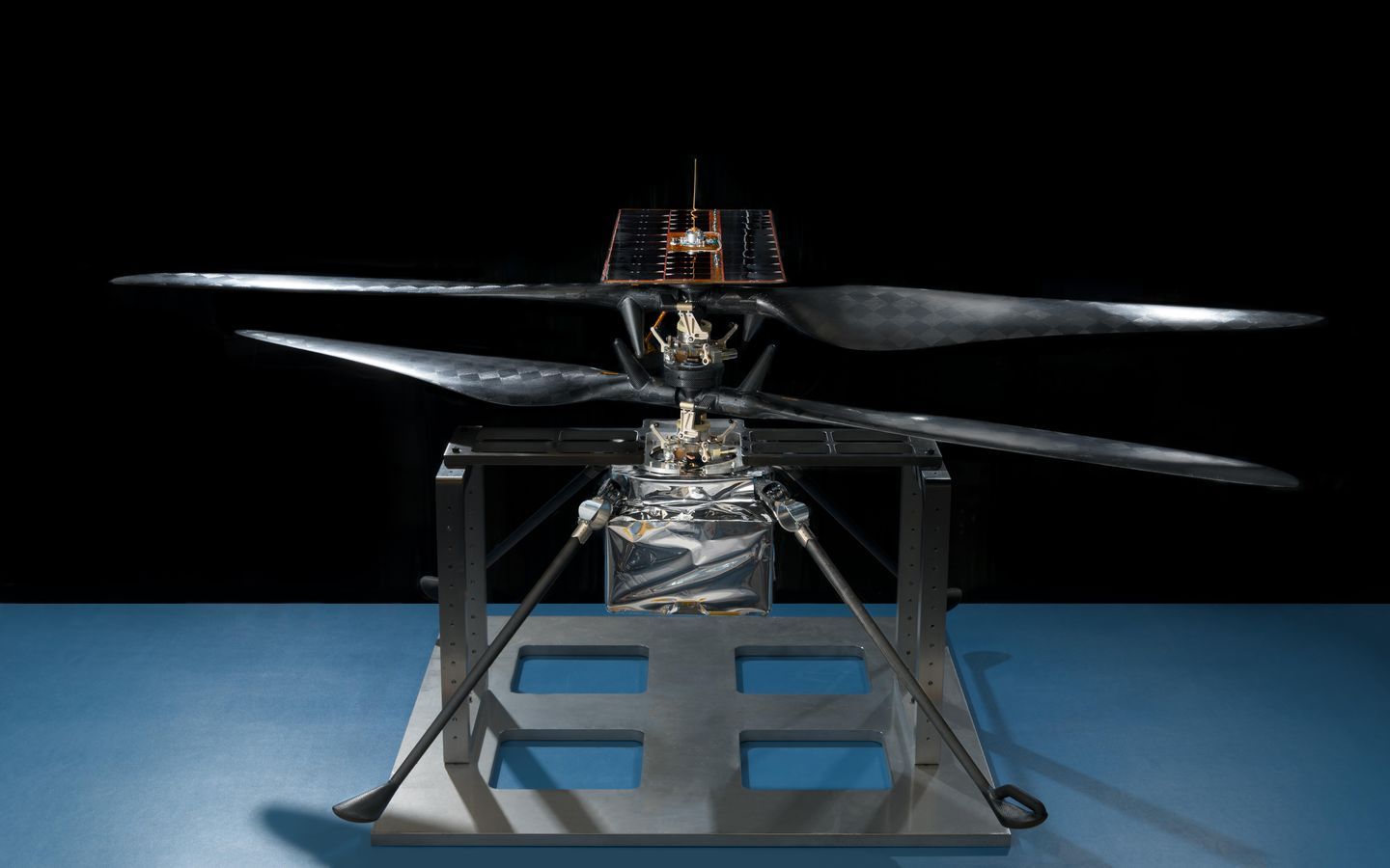
In late January 2019, all the pieces making up the flight model (actual vehicle going to the Red Planet) of NASA's Mars Helicopter were put to the test.

Weighing in at no more than 4 pounds (1.8 kilograms), the helicopter is a technology demonstration project currently going through the rigorous verification process certifying it for Mars.

The majority of the testing the flight model is going through had to do with demonstrating how it can operate on Mars, including how it performs at Mars-like temperatures. Can the helicopter survive—and function—in cold temperatures, including nights with temperatures as low as minus 130 degrees Fahrenheit (minus 90 degrees Celsius)?

All this testing is geared towards February 2021, when the helicopter will reach the surface of the Red Planet, firmly nestled under the belly of the Mars 2020 rover. A few months later, it will be deployed and test flights (up to 90 seconds long) will begin—the first from the surface of another world.

"Gearing up for that first flight on Mars, we have logged over 75 minutes of flying time with an engineering model, which was a close approximation of our helicopter," said MiMi Aung, project manager for the Mars Helicopter at NASA's Jet Propulsion Laboratory in Pasadena, California. "But this recent test of the flight model was the real deal. This is our helicopter bound for Mars. We needed to see that it worked as advertised."

"The Martian atmosphere is only about one percent the density of Earth's," said Aung. "Our test flights could have similar atmospheric density here on Earth—if you put your airfield 100,000 feet (30,480 meters) up. So you can't go somewhere and find that. You have to make it."

Aung and her Mars Helicopter team did just that in JPL's Space Simulator, a 25-foot-wide (7.62-meter-wide) vacuum chamber. First, the team created a vacuum that sucks out all the nitrogen, oxygen and other gases from the air inside the mammoth cylinder. In their place the team injected carbon dioxide, the chief ingredient of Mars' atmosphere.

"Getting our helicopter into an extremely thin atmosphere is only part of the challenge," said Teddy Tzanetos, test conductor for the Mars Helicopter at JPL. "To truly simulate flying on Mars we have to take away two-thirds of Earth's gravity, because Mars' gravity is that much weaker."

The team accomplished this with a gravity offload system—a motorized lanyard attached to the top of the helicopter to provide an uninterrupted tug equivalent to two-thirds of Earth's gravity. While the team was understandably concerned with how the helicopter would fare on its first flight, they were equally concerned with how the gravity offload system would perform.

"The gravity offload system performed perfectly, just like our helicopter," said Tzanetos. "We only required a 2-inch (5-centimeter) hover to obtain all the data sets needed to confirm that our Mars helicopter flies autonomously as designed in a thin Mars-like atmosphere; there was no need to go higher. It was a heck of a first flight."

The Mars Helicopter's first flight was followed up by a second in the vacuum chamber the following day. Logging a grand total of one minute of flight time at an altitude of 2 inches (5 centimeters), more than 1,500 individual pieces of carbon fiber, flight-grade aluminum, silicon, copper, foil and foam have proven that they can work together as a cohesive unit.

"The next time we fly, we fly on Mars," said Aung. "Watching our helicopter go through its paces in the chamber, I couldn't help but think about the historic vehicles that have been in there in the past. The chamber hosted missions from the Ranger Moon probes to the Voyagers to Cassini, and every Mars rover ever flown. To see our helicopter in there reminded me we are on our way to making a little chunk of space history as well."

The Mars Helicopter project at JPL in Pasadena, California, manages the helicopter development for the Science Mission Directorate at NASA Headquarters in Washington.

The Mars Helicopter will launch as a technology demonstrator with the Mars 2020 rover on a United Launch Alliance Atlas V rocket in July 2020 from Space Launch Complex 41 at Cape Canaveral Air Force Station, Florida. It is expected to reach Mars in February 2021.

The 2020 rover will conduct geological assessments of its landing site on Mars, determine the habitability of the environment, search for signs of ancient Martian life, and assess natural resources and hazards for future human explorers. Scientists will use the instruments aboard the rover to identify and collect samples of rock and soil, encase them in sealed tubes, and leave them on the planet's surface for potential return to Earth on a future Mars mission.



1-nasasmarshel.jpg

nasasmarshel.jpg

MzI2NDk5NQ.jpeg
 
Very, very cool, but... if the atmosphere is so thin in the test chamber why can we hear the helicopter running? I'd expect sound wouldn't travel well at all in a 1% atmo regardless of composition. (obviously I'm wrong, but it is curious)
 
Turns out 1% is enough to transmit sound well enough, given the vigorous blade action going on. But, I've got a different question:

First, if this is "the actual helicopter" going to Mars (as stated in the video), flight readiness is proven just by a 2 inch hover? Seriously? You'd think they would have it do some programmed laps around the test area or something to show it can actually maneuver on its own. No joystick flying when it is on Mars... Seems kinda skimpy testing. How does it ensure it lands on a flat surface so it doesn't tip over?

And, if that really was a near vacuum chamber, how did the scientists BREATHE in there dude? ;-)
 
And, if that really was a near vacuum chamber, how did the scientists BREATHE in there dude? ;-)
They let the air back in before they went inside, dude! Also they'd have died of burst lungs and other issues from vacuum before lack of air to "breathe" would have been a problem. Those masks were to maintain "Clean room" conditions.

First, if this is "the actual helicopter" going to Mars (as stated in the video), flight readiness is proven just by a 2 inch hover? Seriously? You'd think they would have it do some programmed laps around the test area or something to show it can actually maneuver on its own. No joystick flying when it is on Mars... Seems kinda skimpy testing. How does it ensure it lands on a flat surface so it doesn't tip over?

They did a lot of hi-fidelity computer simulations. AND testing of a prototype that proved the control systems maneuvered it as desired, in the same vacuum chamber. That testing did more than a 2 inch hover, but didn't go doing laps either, since the control system either works as programmed to do, or it does not. The 2 inch hover flight of the ACTUAL Mars Copter was to confirm it was assembled 100% properly and ready for flight. NASA never got to try that trick with the Lunar Modules that were launched (indeed the first time the LM engines were ever fired were in space, or taking off from the moon. The nasty effects of the hypergolic fuels ruined the engines for further use, so the actual flight engines never got static fired).

I presume there was some other "real world" testing of other aspects of the copter systems, with autonomous free flight to check out the navigation, video, data transmission, and so forth. Did not have to be a Mars-rated vehicle to do that, and of course the Earth's far denser atmosphere and greater gravity would not give realistic flight results. Still, I would expect they used an Earth-Rated crude prototype to test out what they could.

As for not tipping over..... if it flies under proper control, it avoids tipping over by doing a vertical descent, avoiding obstacles like rocks, and trying to avoid any slopes. Since this is going to only "hop" once a day, the JPL ground team will no doubt CAREFULLY chose where they want to to fly to, and EXACTLY where they want to tell it to land at, which should at the least be a flat surface. I've not read the full report (below), but I figure it is likely that it has means of detecting rocks or other objects where it is programmed to land at, with a capability to maneuver enough to dodge them (but I SWAG that the odds may be 1 in 100 that it'll eventually hit a big enough rock/boulder that it didn't detect and may flip over.

If it does not fly under proper control, tipping over won't be as much of a problem as a total crash.

Note this is a prototype being tested a year ago, at least. The actual test footage begins at about 40 seconds. It does pitch, yaw, and roll tests, as well as vertical ascent/descent of course. They didn't need to do a lot of maneuvering, checking the data of the response to those control inputs both confirmed it worked and gave real-world data for tweaking the flight control software. Of course they would not have done only one test of the prototype


Wiki: https://en.wikipedia.org/wiki/JPL_Mars_Helicopter_Scout

January 2018 report on the project: https://rotorcraft.arc.nasa.gov/Publications/files/Balaram_AIAA2018_0023.pdf

Man, I gotta get back to my newest project so I can get far enough along to make it public. :).
 
Last edited:
JUNE 6, 2019
NASA's Mars Helicopter Testing Enters Final Phase

https://www.jpl.nasa.gov/news/news.php?feature=7417

As a technology demonstrator, the Mars Helicopter carries no science instruments. Its purpose is to confirm that powered flight in the tenuous Martian atmosphere (which has 1% the density of Earth's) is possible and that it can be controlled from Earth over large interplanetary distances. But the helicopter also carries a camera capable of providing high-resolution color images to further demonstrate the vehicle's potential for documenting the Red Planet.

Future Mars missions could enlist second-generation helicopters to add an aerial dimension to their explorations. They could investigate previously unvisited or difficult-to-reach destinations such as cliffs, caves and deep craters, act as scouts for human crews or carry small payloads from one location to another. But before any of that happens, a test vehicle has to prove it is possible.

The Mars Helicopter returned to JPL on May 11, 2019, for further testing and finishing touches. Among the highlights: A new solar panel that will power the helicopter has been installed, and the vehicle's rotor blades have been spun up to ensure that the more than 1,500 individual pieces of carbon fiber, flight-grade aluminum, silicon, copper, foil and aerogel continue to work as a cohesive unit. Of course, there's more testing to come.

"We expect to complete our final tests and refinements and deliver the helicopter to the High Bay 1 clean room for integration with the rover sometime this summer," said Aung, "but we will never really be done with testing the helicopter until we fly at Mars."


PIA23151-16.jpg


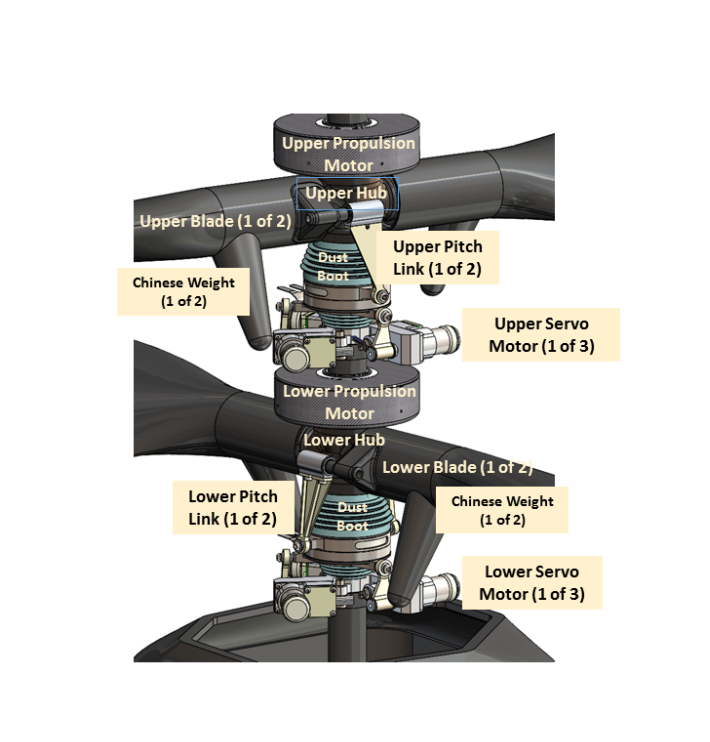
I wondered what those horns were near the blade centers and found this:

screen-shot-2018-05-15-at-12-47-04-pm-1526402893.png

Chinese weights

https://www.rcheliwiki.com/Chinese_weights

Chinese weights are small weights attached to the tail rotor blade grips perpendicular to the plane of rotation.

The purpose of the weights is to oppose the so-called 'tennis racket effect' that causes the blades to exert a force that tends to return them to zero pitch, and so reduce the amount of force required to control the tail blade pitch, improving it's responsiveness. Typically these forces are only an issue with very large blades, or with CNC blade grips.

Since the Mars 'copter main rotors necessarily rotate at such high RPM, "Chinese weights" are needed.


FLIGHT DYNAMICS OF A MARS HELICOPTER (2017)

https://rotorcraft.arc.nasa.gov/Publications/files/ERF2017_final.pdf

The current Mars Helicopter baseline design features a coaxial rotor, with two counter-rotating, hingeless, 2-bladed rotors measuring 1.21 m in diameter, spaced apart by approximately 17% of the rotor radius. The rotors are designed to operate at speeds up to 2800 RPM. The speed is fixed for the duration of flight, depending primarily on the current density, which is in the range 0.014–0.02 kg/m3. Control is via upper and lower swashplates, providing collective control with a total range of 22◦, and cyclic control with a range of ±10◦, for each rotor.

Within the allowable density range, the vehicle is designed to have the power and aerodynamic capability to achieve thrust levels of at least 40% above hover thrust before the onset of stall. The helicopter would only fly in favorable weather, with wind velocities limited to 9 m/s horizontally and 2 m/s vertically, with a maximum gust component of 3.5 m/s. Based on the forecasted weather, ground speed and climb/descent speeds would be limited such that maximum airspeed does not exceed 10 m/s horizontally and 3 m/s vertically.

The gross vehicle weight is less than 1.8 kg, a substantial portion of which is taken up by the batteries. The batteries provide energy for flights lasting up to 90 s, while also providing sufficient energy for non-flight operation of the onboard electronics and night-time survival heating. The batteries are rechargeable via a solar panel mounted on the nonrotating mast above the upper rotor. The batteries and other electronics are housed in a cube-like fuselage attached to the central mast, inside of which is a warm electronics box that is properly insulated and heated to protect against low night-time temperatures.

Flights would be conducted based on a flight plan uploaded from the ground, consisting of a series of waypoints. Due to the many minutes of communication delay between Earth and Mars, each flight must be conducted with full autonomy. For this purpose, onboard navigation is performed using a combination of a small, MEMS-based inertial measurement unit (IMU), a low-resolution downward looking camera, and a laser rangefinder. The IMU, which measures accelerations and angular rates, is used for propagation of the vehicle state from one time step to the next. The camera is used together with the laser rangefinder to determine the height above ground and the translational velocity; this information is fused with the IMU solution.

The onboard computation platform consists of a radiation tolerant FPGA; a dual-redundant automotive-class microcontroller hosting the most critical flight control functions; and a cell-phone class processor hosting the vision-based navigation functions.

...it should attain ~100m altitude and ~600m ground track. Daily communication of helicopter data will provide overhead image resolution ~10x greater than orbital images, and greater area coverage than can be seen from the rover.


JPL Mars Helicopter Scout

https://en.wikipedia.org/wiki/JPL_Mars_Helicopter_Scout

Its payload will be a high resolution downward-looking camera for navigation, landing, and science surveying of the terrain, and a communication system to relay data to the 2020 Mars rover.[14] Although it is an aircraft, it is being constructed as a spacecraft in order to endure the g-force and vibration during launch. It also includes radiation-resistant systems capable of operating in the frigid environment of Mars.

The inconsistent Mars magnetic field precludes the use of a compass for navigation, so it will use a solar tracker camera integrated to JPL's visual inertial navigation system. Some additional inputs might include gyros, visual odometry, tilt sensors, altimeter, and hazard detectors.[15] It will use solar panels to recharge its batteries, which are six Sony Li-ion cells with a nameplate capacity of 2 Ah.[10]

The prototype uses the Snapdragon processor from Intrinsyc with a Linux operating system,[10] which also implements visual navigation via a velocity estimate derived from features tracked with a camera.[10] The processor is connected to two flight-control Microcontroller Units (MCU) to perform the needed flight-control functions.[10] Communications with the rover are through a radio link called Zig-Bee, a standard 900 MHz chipset that will be mounted in both the rover and helicopter.[10] The communication system is designed to relay data at 250 kb/s over distances of up to 1,000 m.[10]
The helicopter will be attached to the underside of the rover. It will be deployed to the surface between 60 and 90 Martian days after the landing, and then the rover will drive approximately 100 meters away for the test flights to begin.[16][17]
 
Mars Helicopter Technology Demonstrator (2018)

https://rotorcraft.arc.nasa.gov/Publications/files/Balaram_AIAA2018_0023.pdf

C. Avionics Computing

A three-level fault-tolerant computing architecture is used on the helicopter as shown in Fig. 9. Software is implemented using the F’ software framework [10]. The avionics design is required to have low mass, low power and adequate radiation tolerance. A set of candidate parts to meet these requirements have been incorporated into the design which is now described.

1. Processors

The SnapdragonTM processor from Intrinsyc® with a Linux operating system performs high-level functions on the helicopter. The SnapdragonTM processor has a 2.26 GHz Quad-core SnapdragonTM 801 processor with 2 GB Random Access Memory (RAM), 32 GB Flash memory, a Universal Asynchronous Receiver Transmitter (UART), a Serial Peripheral Interface (SPI), General Purpose Input/Ouput (GPIO), a 4000 pixel color camera, and a Video Graphics Array (VGA) black-and-white camera. This processor implements visual navigation via a velocity estimate derived from features tracked in the VGA camera, filter propagation for use in flight control, data management, command processing, telemetry generation, and radio communication.

The SnapdragonTM processor is connected to two flight-control (FC) Microcontroller Units (MCU) via a Universal Asynchronous Receiver/Transmitter (UART). These MCU processor units operate redundantly, receiving and processing identical sensor data to perform the flight-control functions necessary to keep the vehicle flying in the air. At any given time, one of the MCU is active with the other waiting to be hot-swapped in case of a fault. The MCU from Texas Instruments is a TMS570LC43x high-reliability automotive processor operating at 300 MHz, with 512 K RAM, 4 MB flash memory, UART, SPI, GPIO.

2. Avionics Boards

The avionics consists of 5 printed circuit boards which form the 5 facets of the ECM (Electronic Core Module) cube, enclosing the 6-cell lithium-ion battery pack. The boards are shown in Fig. 10.

The bottom of the cube is the battery interface board (BIB), which is attached to the battery and hosts the battery monitoring circuitry, motor power switches and motor current monitors. The battery and the BIB can be detached from helicopter and is intended to be replaceable.

The remaining 4 boards are the FPGA/Flight Controller Board (FFB), the NAV/Servo Controller Board (NSB), the Telecom Board (TCB) and the Helicopter Power Board (HPB):

• FFB. The FFB is at the heart of the ECM. The two redundant TI Hercules safety processors serve as the low-level flight controller (FC); each has dual-core lockstep ARM Cortex-R5F and ECC protected Flash and RAM. The two processors run in sync and are provided with the same clock and data by the FPGA, which handles all the sensors and actuators interface. The lockstep mechanism does cycle by cycle error detection. If a fault is detected, it signals the error to the FPGA; the FPGA switches to the other processor and power cycles the faulty one, so the flight control software continues to run without disruption. The analog signals are digitized by the two independent 12-bit ADCs in each of the flight controllers.
• NSB. The NSB carries the Snapdragon CPU as a System on a Module (SOM) and provides power and I/O interfaces which include 3 UARTs, 1 SPI and a few discrete GPIOs. The NSB also hosts the drive circuitry for the 6 DC servo motors and delivers over 20 W power.
• TCB. The COTS telecom module is mounted on the TCB. Some additional analog circuitry, a 16-bit 8-channel ADC, the temperature sensor interface and heater switches take up the remaining space. This ADC is used for monitoring charging current and temperature without having to turn on the FCs, thereby saving power.
• HPB. The HPB has two DC/DC converters that regulate the battery voltage to the 3.3 V and the 5 V. The 5 V regulator can be switched off.
Although COTS electronics parts are used, selections are made for military-grade, automotive or industrial grade with the operating temperature range of at least -40 C to +85 C. The ICs are screened for single-event latch-up (SEL) and parts are also selected for low power. Each subsystem has a current monitor to detect possible latch-up current and can be power cycled to clear a SEL. In addition, current limiting is added to prevent a destructive SEL event and most devices are switched off when not in use to minimize their exposure to SEL. For the critical FPGA which is always on for the duration of the mission, the radiation tolerant ProASIC3 is chosen with the military temperature grade (-55 C to 125 C) and -1 speed grade to mitigate the degradation in the propagation delay caused by the total dose radiation. The single-event upset (SEU) is mitigated with triple module redundancy (TMR) in the FPGA design.
 
3. FPGA

At the heart of the helicopter avionics is a Field-Programmable Gate Array (FPGA). The FPGA implements the custom digital functions not implemented in software due to resource limitations of the processors (e.g. I/O or bandwidth limits), timing requirements, power considerations, or fault tolerance considerations. The FPGA device is a military-grade version of MicroSemi’s ProASIC3L, which uses the same silicon as the radiation-tolerant device from the same family. The FPGA perform all critical I/O to the sensors and actuators, and fault managment functions including detecting error flags from the MCU and hot-swapping to the functioning MCU in case of an error.

The FPGA performs vehicle flight control including an attitude control loop operating at 500 Hz, an outer motor control loop, waypoint guidance, sensor I/O from the IMU, altimeter and inclinometer, and analog telemetry for current and temperature sensing. It is responsible for system time management, interfaces to the IMU, altimeter and inclinometer sensors. It implements the “inner” motor control loop used for the two brushless rotor motors and the six brushed motor servos (three at each rotor swashplate), as well as power management and thermal control functions.

Most communication on the helicopter avionics flows through the FPGA. The FPGA implements 25 separate serial data interfaces (SPI, I2C, UART, SENT) to enable multiple paths of communication between the three processors, GNC devices (both IMUs, altimeter, inclinometer), all 8 motors, battery monitor, and external ADC. During cruise, and prior to deployment, the helicopter FPGA communicates to the FPGA on the base station to report telemetry.

Once the helicopter is deployed from the host spacecraft, the FPGA manages the power and operational state for the entire helicopter. It turns on and off the other avionics elements as they are needed, implements thermostat control of the survival and operational heaters, monitors the battery cell voltages, and performs cell balancing. Being one of only two elements that is always powered post-deployment (the other is the battery monitor), the FPGA maintains precision spacecraft time, implements alarm clock functions, and generates real-time interrupts for the rest of the system.

The helicopter FPGA implements most of the fault protection on the vehicle. It collects telemetry and health status from a variety of sources and responds to them as a function of the operational state. It operates the pair of FC processors as a primary and hot spare, determining when to switch from one to the other, and restoring critical state data to a processor after it has been power cycled. Critical data used by any of the processors is stored in the FPGA. Triple module redundancy is applied to critical flip-flops, as resources permit, to add additional protection from SEU. Helicopter motor control is divided between the FPGA and software. For each of the six, brushed DC motor servo controllers, the FPGA generates the PWM drive signals and reads the absolute position sensor. For the two brushless DC rotor motors, the FPGA implements the commutation loop, driving the motors with space vector PWM (SVPWM).

A closed-loop angle tracker produces a rate measurement and a smooth, low-lag, angle measurement from the Hall signals that feeds into the SVPWM algorithm. The FPGA also implements novel approaches to compensate for the inductive lag of the motor and calibrate out variations of the Hall sensors.

D. Sensors

On-board sensors are used for vehicle control during all phases of flight. Data from IMU’s, an altimeter, and navigation camera image derived velocimetry is used to produce a navigation solution consisting of helicopter position, velocity, attitude, and other auxiliary variables. An inclinometer is used on the ground prior to flight to calibrate the IMU accelerometers biases. The helicopter also carries a color camera to provide images of terrain and other features for return to Earth.

The sensors used are Commercial-Off-The-Shelf (COTS) products. The candidate set of parts include:

• IMU. These are two 3-axis MEMS device from Bosch (Sensortec BMI-160), one for the upper sensor assembly in a vibration isolation mount, and one on the lower sensor assembly where it is co-located with the cameras.
• Inclinometer. This is a 2-axis MEMS MuRata device (SCA100T-D02)
• Altimeter. This is a time-of-flight altimeter with a range of 10’s of meters from Garmin (Lidar-Lite-V3).
• Navigation (NAV) Camera. This is a global-shutter, nadir pointed grayscale 640 by 480 pixel sensor (Omnivision 13 Downloaded by NASA AMES RESEARCH CENTER on January 8, 2018 | https://arc.aiaa.org | DOI: 10.2514/6.2018-0023 OV7251) mounted to a Sunny optics module. It has a field-of-view (FOV) of 133 deg (horizoontal) by 100 deg (vertical) with an average Instantaneous Field-of-view (IFOV) of 3.6 mRad/pixel, and is capable of acquiring images at 10 frames/sec. Visual features are extracted from the images and tracked from frame to frame to provide a velocity estimate.
• Return-to-Earth (RTE) Camera. This is a rolling shutter, high-resolution 4208 by 3120 pixel sensor (Sony IMX 214) with a Bayer color filter array mated with an O-film optics module. This camera has a FOV of 47 deg (horizontal) by 47 deg (vertical) with an average IFOV of 0.26 mRad/pixel. Both cameras are mounted on the helicopter Lower Sensor Assembly as shown below in Fig. 11. The NAV camera is pointed directly towards nadir, and the RTE camera is pointed approximately 22 deg below the horizon, resulting in an overlap region between the two camera image footprints of approximately 30 deg × 47 deg. The overlap allows the possibility of feature registration between NAV and RTE images during post-flight data processing on Earth.


Guidance and Control for a Mars Helicopter (2018)

https://rotorcraft.arc.nasa.gov/Publications/files/Grip_AIAA2018_1849.pdf

Rotorcraft as Mars Scouts (2002)

https://www.researchgate.net/publication/3968849_Rotorcraft_as_Mars_Scouts/download
 
Back
Top