mikec
Well-Known Member
- Joined
- May 9, 2009
- Messages
- 3,033
- Reaction score
- 840
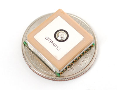
There isn't any device I'm aware of that's pin-compatible with the UP501; a revision to the board will be needed.Did anyone ever find a suitable replacement for the UP501 GPS module that will work with current PCB's?
You can still buy the UP501 on ebay but there are only 60 or so left so if you want one I'd get it ASAP.
https://www.ebay.com/itm/High-perfo...074?pt=LH_DefaultDomain_0&hash=item27cf28c8b2