Rocket Track - Open Source GPS Tracker for Smartphones

The Rocketry Forum

Help Support The Rocketry Forum:

This site may earn a commission from merchant affiliate links, including eBay, Amazon, and others.
It's not optimal, but if you don't need 100% range it may be OK. If you can keep the distance to at least 1/2 of the antenna length (about 1 5/8") then it shouldn't have much effect.

Hope RF has a good guideline document for antennas, it's applicable to just about any of the ISM band RF modules that you're going to see. Its at https://www.hoperf.com/upload/rf/ANTENNAS_MODULE.pdf

How far away? There are two 8" treaded rods that run the length of the AV bay, the clearance will only be 1 to 2 inches. Is that enough?


TA
 
Whatever you do don't fold the wire antenna back over the transmitter pcb! The pcb has a ground plane covering most of it and will pretty effectively block the signal if it gets between you and the antenna. I had one user ask why the range was terrible and that turned out to be the reason.

Like previously mentioned the optimal direction is straight out of the top of the board, but unless you have a really fat rocket that isn't practical. I try to angle it so it is sticking out as much as possible.
 
Just another question, can you use a single receiver and multiple trackers that will work together? Not necessarily at the same time but one receiver and a tracker for each rocket or at least multiple trackers so more than one rocket could be set up at a time.
 
Why would folding the whip antenna forward (along the axis of the rocket) be any worse than coming straight out of the board?
 
FORWARD (away from the board) is OK. You just don't want to tuck it under/over the board, because the ground plane on the board blocks the signal.
 
Because it's a 1/4-wave monopole antenna and it's using the Xbee board as a ground plane.
https://www.antenna-theory.com/antennas/monopole.php

How much of a difference this really makes in practice -- harder to say.

Ah, thanks.

The varying of the polarization of the XBee antenna (in the nose cone) during decent on a drougeless flight has me wondering what the best orientation of a dipole ground antenna should be. I'm assuming for the ground station it is best to have the dipole horizontally polarized ( pointing straight up), or would it be better to have it lay horizontally (vertically polarized)?
 
Last edited:
Because it's a 1/4-wave monopole antenna and it's using the Xbee board as a ground plane.
https://www.antenna-theory.com/antennas/monopole.php

How much of a difference this really makes in practice -- harder to say.

Does it make any sense to have a grounded copper foil covered bulkhead that would be perpendicular to the an axial monopole? Seems like it could be integrated onto the tracker AV bay design. An SMA could slide through the hole in the ground plane bulkhead and the hex nut would hold it in place and make the ground connection.
 
Just another question, can you use a single receiver and multiple trackers that will work together? Not necessarily at the same time but one receiver and a tracker for each rocket or at least multiple trackers so more than one rocket could be set up at a time.

Yes, that will work as long as only one transmitter is turned on at a time.
 
Does it make any sense to have a grounded copper foil covered bulkhead that would be perpendicular to the an axial monopole?
Having a large ground plane is going to wipe out the antenna pattern below the ground plane, which might reduce radiated power in that direction while improving it in others. Since the orientation in flight is moving all over, especially during descent, this could hurt as much as help.

That said, there's probably a lot that could be done with antenna design, but the real question is, do you need to bother? I typically fly these on rockets that don't go much above 10Kfeet and land at most a mile or two away. So far, I've always gotten enough packets back with good GPS data to recover the rocket. Since the Xbees have a rated range of 6-9 miles I'm not really pushing their envelope too hard.

Makes sense, thanks. I have had a hard time figuring out what the actual in air RF range is with my setups, but I suspect it is not much more than a couple miles. It would be nice to use it for flights above 10k feet so maybe I need to think about some Tx and Rx antenna upgrades.
 
Doesn't the TeleMetrum use a Venus634FLPx?

Early boards did. Later 1.x boards moved to the 638.

We've moved to the u-blox MAX-7Q for TeleMega and will be using it on TeleMetrum v2 which we hope to start production on this month. In fact, everything about the new TeleMetrum boards is improved... definitely take a fresh look once we announce them!
 
Having a large ground plane is going to wipe out the antenna pattern below the ground plane, which might reduce radiated power in that direction while improving it in others. Since the orientation in flight is moving all over, especially during descent, this could hurt as much as help.

That said, there's probably a lot that could be done with antenna design, but the real question is, do you need to bother? I typically fly these on rockets that don't go much above 10Kfeet and land at most a mile or two away. So far, I've always gotten enough packets back with good GPS data to recover the rocket. Since the Xbees have a rated range of 6-9 miles I'm not really pushing their envelope too hard.

I've been thinking about this for a while now and that is pretty much the conclusion I've come to. You may improve some scenarios but hurt others. But your're welcome to try it and report your findings! :)
 
FORWARD (away from the board) is OK. You just don't want to tuck it under/over the board, because the ground plane on the board blocks the signal.

yes! I really need to take some pictures of proper and improper antenna orientation. Maybe if I get some time this weekend.
 
maybe I need to think about some Tx and Rx antenna upgrades.
Since you can never control the orientation of the rocket and all omni antennas have about the same performance, if you want more range your only real option is to use a directional antenna on the ground. You will have to worry about keeping it pointed at the rocket, and depending on how directional it is, that could be fairly easy or quite difficult.

I've never really done any range testing on the Xbee, only verified that Digi's claims are plausible using simple link margin calculations. At 250 mW, the newer S3B module should be good to 9 miles with omni antennas on both ends, which is probably enough for all but the most extreme flights. The highest flight I've done was with the old 100mW 6-mile module; just over 15Kfeet and landed less than a mile away.
 
Here's an example of a nose sled with the antenna pointing upwards, this is from a Giant Leap Escape Velocity. The sled slides into a cutout in the nose (it's purposely a tight fit), and the end gets zip tied to the screw eye shoulder. A little masking tape over the opening to keep out any ejection charge gases and you're in business.

EV Eggfinder Nose Sled.jpg
 
Ordered TX and RX PCB set, I will give a try to the Derek stuff, I like to have the GPS and Xbee solder on the same board, no wires is way cleaner and more reliable.
 
So I built the tracker and receiver, but I am unable to connect the batteries to either because the adapter to connect the batteries to the PCB were not included in the parts list. So far everything is going great, but I'm not really sure how to actually connect the batteries. Any help is greatly appreciated. I know it is a remedial question, but I am new to electronics end of rocketry and need help.
 
If you bought the batteries that I show with the red connectors, then you need some jst leads. You can find them on eBay or at places like hobbyking.
 
Now that I'm back from vacation I can provide you with a little more info on the battery connectors. The batteries I use have male JST connectors on them so you'll need female JST leads to solder to the boards. I bought a 10 pack of male and female sets on ebay for 4 - $5. You can also buy them from places like Hobby King, rc-connectors.com or your local hobby shop. Anything from 22 to 26 gauge wire will be fine as the boards don't draw a lot of current.

I'll plug rc-connectors.com as I've bought some of these from them and the quality and speed of delivery were fine, but they aren't the cheapest source.

jst-female-22-6.JPG


https://www.rc-connectors.com/index.php?main_page=product_info&cPath=98&products_id=323

I also added info about the connectors to the build posts. Thanks for pointing out that ommision!
 
that cable can program both the xbee and bt modules but you don't need to buy it. you can use a regular xbee to usb adapter as long as you haven't soldered the modules onto the pcbs yet. you can also get creative with an arduino or maybe even the eggtimer serial adapter, but you have to make sure the voltages are correct for both of these otherwise you could damage the modules.

but yeah, you need something. that cable is the cheapest solution if you need to buy something, which is why I chose it.
 
welp that didn't take long to screw up. lol

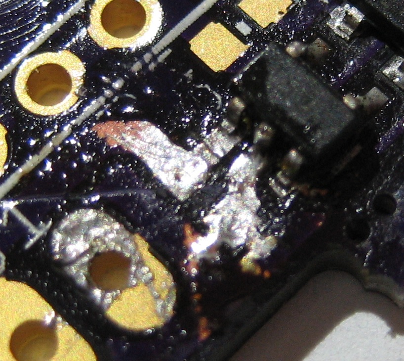
Working on the transmitter and when soldering C2 it appears the left conenction is bridged to the left of the 3 connectors on U2. Using my meter set to olms I get a signal if I touch both spots. sigh. So I've been working at trying to remove that bridge for over 30 minutes now. I figured the braid I have would pick it up but the braid seems to either absorb very little or none at all and every time I recheck with the meter I still get a signal. I'm assuming that the design of the board isn't giving me that signal right, as in if they were hooked up correctly I wouldn't get a olms signal right?

Any suggestions on how to break the bridge. It appears to be a super thin layer that is connecting the two and the braid just isn't doing what I though it would. This has been way harder than I predicted it would be. :eek:

33972497246239167765.jpg
 
Last edited:
There's a lot of solder splatter on the board, you might want to try using a cooler iron and/or finer tip. This happens because the flux in the solder boils off instead of melting and gradually evaporating; it's especially a problem with low-melting solders and solder creams. I ran into this issue when I first starting mount SMT parts on early Eggtimer prototypes, the trick was to preheat the board and parts at about 150C for about a minute before turning up the temperature.

It also looks like there's some voids in the solder mask, your solder bridges are probably shorting to ground.
 
Using my meter set to [ohms] I get a signal if I touch both spots.
If the resistance is more than a few ohms, you're probably looking at a path inside the chip that you don't need to worry about.
 
There's a lot of solder splatter on the board, you might want to try using a cooler iron and/or finer tip. This happens because the flux in the solder boils off instead of melting and gradually evaporating; it's especially a problem with low-melting solders and solder creams. I ran into this issue when I first starting mount SMT parts on early Eggtimer prototypes, the trick was to preheat the board and parts at about 150C for about a minute before turning up the temperature.

It also looks like there's some voids in the solder mask, your solder bridges are probably shorting to ground.

Most of that mess on there is flux. Only the shiney parts is the solder. I was going a bit nuts with the flux and the braid trying to get that off. Pretty sure I'm just going to have to order another board. sigh.
 
Most of that mess on there is flux.
Have you cleaned the board with some IPA? Do you really have a short or just a path inside U2?

You should be able to assemble this board with rosin-core solder and no flux unless your part leads are highly oxidized.
 
Have you cleaned the board with some IPA? Do you really have a short or just a path inside U2?

You should be able to assemble this board with rosin-core solder and no flux unless your part leads are highly oxidized.

The example videos I watch showed putting the solder on the tip and using flux on the board. ? And I don't know what IPA is.

I am assuming it's a short. My electrical drawing reading skills are not very good (aka almost non-existent) but it appears there is solder connecting the two pads.
 
Did anyone ever find a suitable replacement for the UP501 GPS module that will work with current PCB's?
 
Back
Top