Open Body missile build for my Level 2

The Rocketry Forum

Help Support The Rocketry Forum:

This site may earn a commission from merchant affiliate links, including eBay, Amazon, and others.

jeffgeraci

Well-Known Member
Joined
Mar 4, 2011
Messages
616
Reaction score
11
I'm out of my slump, finally! I've decided to go for my level 2, and i'm going to push my luck on this one.

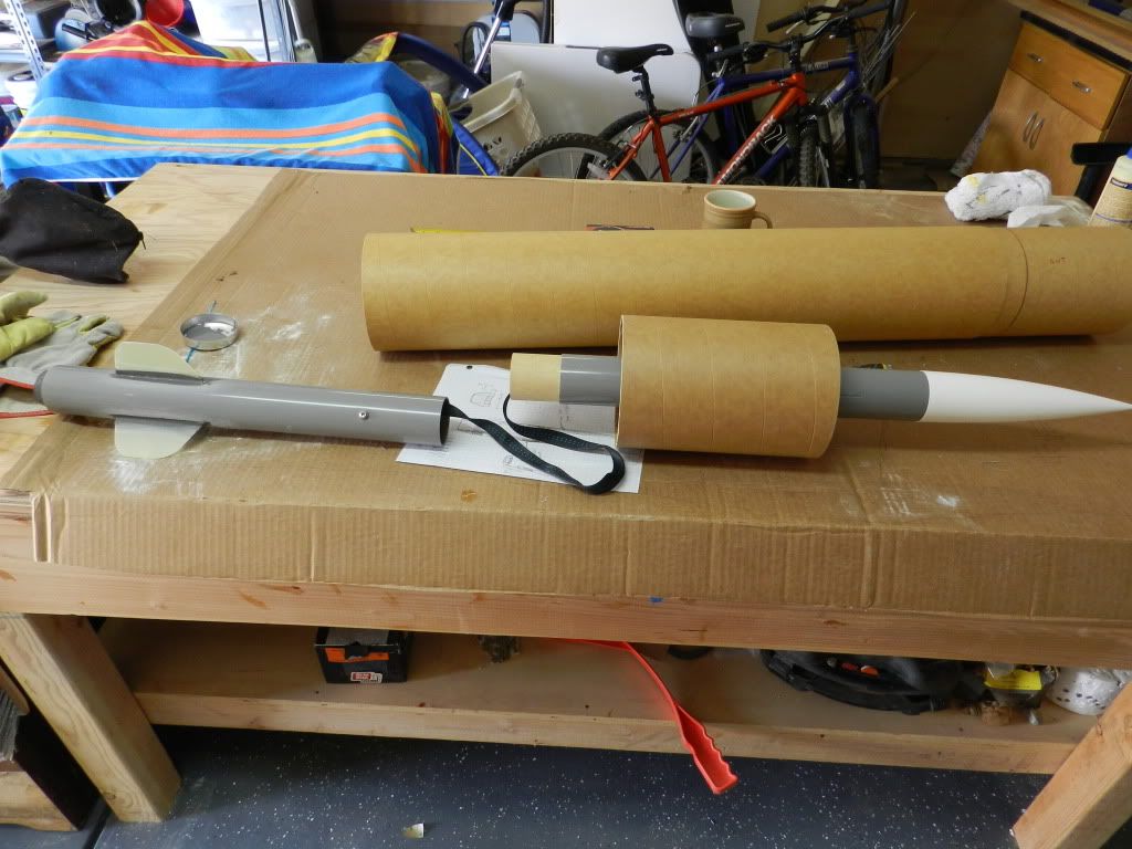
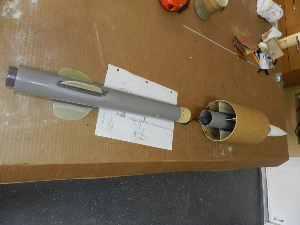
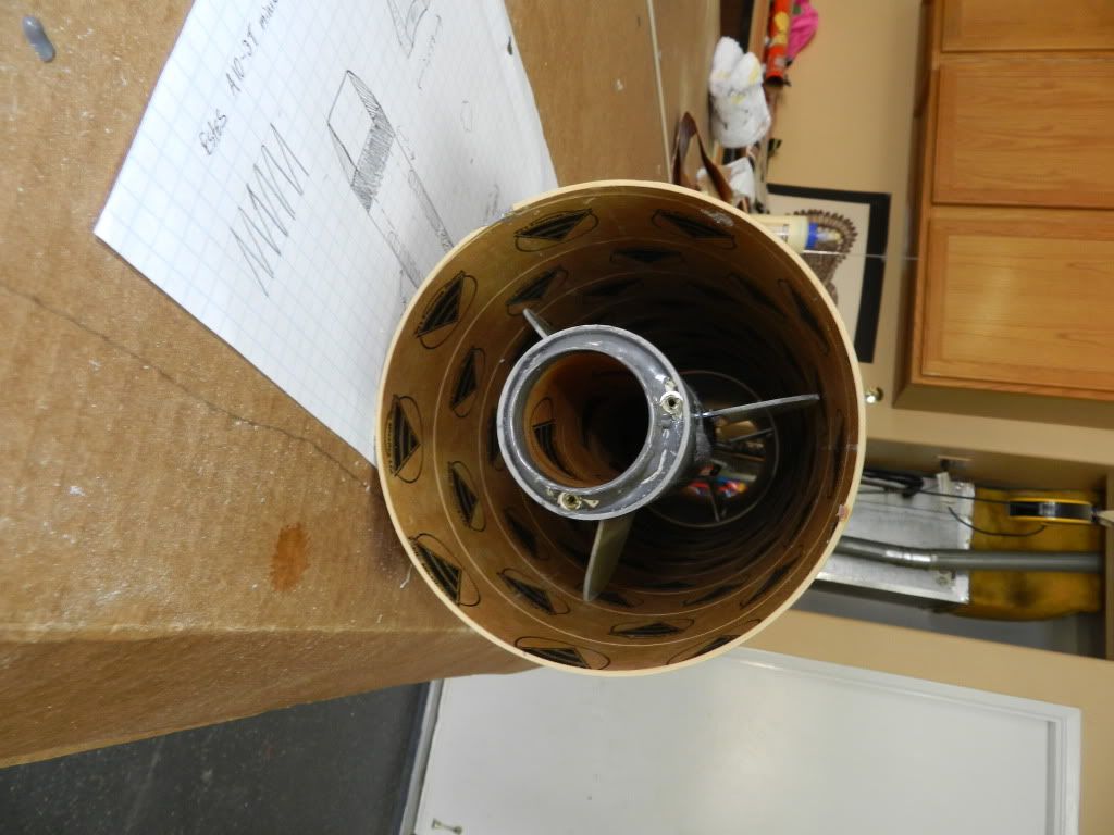
My challenge is to create an open-body rocket, without any nose cone, that can run on a single "J" motor, but then after my cert, I want the option of powering it with 2 or 3 (38mm) motors. Therefore, I want to make the central motor removeable and resizeable, and I plan to run ferrings along two sides to house (2) 38mm motors and recovery systems.

It's not the first open body rocket I'll have built, but this one will be 8 feet long, 6" diameter airframe, and it will be much more powerful. I don't have Rocsim or any of those other fancy programs, because I prefer to experiment. Since I don't draw plans when I build my rockets (I doodle bits of my idea on post-its), I created a couple drawings on the paint program so I can share my plan with you.

This new build thread will have plenty of pictures, and i'll keep it updated. I just want to know if anyone has any thoughts or wants to contribute anything before I go and order the components. I also will need a name, but that can evolve. Thanks!

newrocket 1.JPG

newrocket2.jpg

img120.jpg
 
Last edited:
Now that I like. How are you doing recovery? A parachute in the motor mount tube running inside the main airframe, or something in the side pods?
 
[POW]Eagle159;219222 said:
Is there going to be some sort of cap on the front of the body tube?

No cap, no cone... completely open from front to back.
 
Now that I like. How are you doing recovery? A parachute in the motor mount tube running inside the main airframe, or something in the side pods?

For my cert flight, the chute comes out the back. The rear section of the 2.1" internal airframe pops off at the coupler and pulls the chute out of the front section.

After that, recovery will pop out of side ferring tubes (also 2.1") Good guess!
 
Last edited:
Ya, Ild say you came out of your SLUMP alright! Whats the deal with the fins? They slotted or is that just more doodleing?The name,its in your first post. ;)
 
Last edited:
Just recieved shipment from PML- looks good, except I think the centering rings for the retainer are too narrow to mount the threaded inserts. I'll figure something out, any ideas?

The name so far is: "Dude, where's my nosecone?" Since this is a "noseconeless" rocket build. I'll keep it updated as I progress

roc1.jpg

roc2.jpg
 
DSCN0215.jpg
DSCN0223.jpg
[/IMG]Just constructed the forward section of the removeable motor assembly by epoxying g10 fins along the routered grooves. Then I epoxied the forward section into the 6" coupler.
 
This is going to be a fascinating build. I am curious to see how it all plays out especially the flight. I will say however, if you showed up at one of our launches with that we'd let you fly it but off of one of the away pads and call a heads up of course.

So, just a thought, have you tried packing the chutes? With those tubes I am curious to see how you are going to get enough chute and cord for that size rocket.

-Dave
 
DSCN0231.jpg

DSCN0225.jpg
Here's a view of the removeable motor assembly before its loaded into the rocket body. The aft section of the assembly will separate from the front section at the coupler. This yanks the chute from the front section, while set screws will keep the front section and coupler secured. The 3 small fins on the aft section keep the motor tube centered, but are not glued to the body. They will guide the aft section out of the body upon ejection. I hope I explained that correctly, but I will post a video soon to show how the assembly will function.
 
DSCN0227.jpg
[/IMG] Here's a frontal view of the removeable motor assembly inserted into the rocket body. The coupler in the rocket body acts as a thrust ring for the removeable motor assembly.
 
DSCN0229.jpg

Here's the aft view of the removeable motor assembly inserted into the rocket body. The fins are NOT secured to the body- they serve to (1) center the motor assembly and (2) guide the aft section out during ejection.
 
Very interesting design. I will be following this thread to the end. This is really thinking outside the box!
 
I will say however, if you showed up at one of our launches with that we'd let you fly it but off of one of the away pads and call a heads up of course.

So, just a thought, have you tried packing the chutes? With those tubes I am curious to see how you are going to get enough chute and cord for that size rocket.

-Dave

Funny you say that: I'm used to being shoved way back on the launch pad with my experimental rockets, and good thing they put me there too! I've had some very interesting "almost" launches from the lone pad all the way in the back, but thankfully no land sharks.

With regard to the chutes fitting in the tubes: My last open body rocket (P-29 COBRA) only had 29mm motor tubes, and it was a B%#*@ packing the chutes inside, because they didn't fit. I didn't make that mistake this time- the tubes are 2.25" dia., and I can fit 3 chutes inside them.
Thanks for the feedback, it's appreciated!
 
When I launched the cobra the second time, my kids were a handful and so I got distracted. I wound up mistaking an H-97 for an H-220, so I put an H-97 in one MMT and an H-220 in the other MMT. It was quite the pathetic launch, and the motors didn't even ignite simultaneously, and the crash smushed the face on one side of the Cobra. It's stuffed in my garage somewhere, cause I'm still pissed at it. I think i'll sell it on ebay, starting the bidding at $10. I'll post a video of the launch when I have more time.
 
DSCN0246.jpg
[/IMG]
DSCN0248.jpg
[/IMG]
I installed a centering (that I epoxied to a g10 disc) and fit an eye-bolt through it. I chose to use a toggle clip instead of a nut- not because I’m an innovative genius and realized that a toggle clip will distribute the stress over the whole centering ring, but because I couldn’t find a nut to fit the eyebolt. Anyway, I epoxied this assembly into the front section of the motor assembly to anchor the shock cord- i's not pretty, but it'll work.
 
Wow Jeff, thats an awsome design. Far from just a plain 3FNC rocket. How did you ever think that up? Cant wait to see it fly.
 
Wow Jeff, thats an awsome design. Far from just a plain 3FNC rocket. How did you ever think that up? Cant wait to see it fly.

Thank's Bill. It's actually a very simple design, apart from the side ferrings, which I plan to start in the next couple days (waiting for Rockler to ship the plywood). Those should really make the rocket "pop"
 
(Please pardon me if you know this already) Just a couple of thoughts...Instead of set screws you could use PML's pop rivets. Either way will work fine so whatever you are comfortable with. Phenolic is difficult to cut but standard wood cutting tools work just fine. I have used the following to cut that sort of tubing:

- dremel with an abrasive cut-off wheel (this gets a little smoky)
- hacksaws with a coarse blade
- mitre saw with a plywood blade
- jigsaw
- circular saw

Any of those methods will make a bit of a rough cut so you will need to sand with a sander or whatever to get it pretty. A bench sander is awesome.

-Dave
 
I've changed the design somewhat, and added a color scheme. I'll start the side ferrings Monday if all goes well. At 8 feet tall, it should look pretty cool I hope

roc13.JPG
 
Very neat design!

So, from what it looks to me, you're making a flying ramscoop rocket?

EDIT: Okay, I did a quick model of your rocket on OpenRocket. I won't tell you the details since you like surprises, but so far it looks good.
 
Last edited:
Okay, I did a quick model of your rocket on OpenRocket. I won't tell you the details since you like surprises, but so far it looks good.

Openrocket can't calculate tube fins, which this rocket technically has.
 
Openrocket can't calculate tube fins, which this rocket technically has.

Not exactly... In fact, I just completed the panels for the side ferrings that will house the dual 2.1" side-mounted airframes and 38mm MMT's. You can see what it will look like with the ferrings and fins in these 2 photos:

fin2.JPG

fin1.JPG
 
jeff, you gotta bring whatever's completed to ROCtober next saturday, its definitely going to turn some heads, even just the motor assembly (which is a rocket in itself! :D

also, what material is the motor assembly tube? it looks like a plastic? is it very strong?
 
jeff, you gotta bring whatever's completed to ROCtober next saturday, its definitely going to turn some heads, even just the motor assembly (which is a rocket in itself! :D

also, what material is the motor assembly tube? it looks like a plastic? is it very strong?

Hey Edwin, long time no speak. I'll definitely be there next Saturday, but this rocket won't be ready until the November launch. We're gonna camp out this time, i'm looking forward to a great weekend, I need one!!

The gray tubes are PML's 2.1" quantum airframes, and I had the fin grooves routed in them, so should be an easy assembly. By the way...........I do have a suprise for next Saturday's launch, but I don't want to post on this forum until after the launch- you'll like it.

PS: it's been a while since I had time to surf TRF, so I'm gonna search to see what you've been up to! See ya
 
Finally had time to work on it. Anyway, I just finished assembling the ferrings. I cut a slot for the fins, and routed the edges with a .25" radius router bit. After sanding them down, they look much better than the photos. If you look at the drawing I posted (about 6 posts before this one) you can see where the ferrings go. I hope to attach the ferrings to the airframe this week and start fiberglassing. I've got to get this rocket done by November 11.

roc1.JPG

roc2.JPG

roc3.JPG
 
Back
Top