You are using an out of date browser. It may not display this or other websites correctly.
You should upgrade or use an alternative browser.
You should upgrade or use an alternative browser.
Iris BT70 build =scale=
- Thread starter Balltip
- Start date


Help Support The Rocketry Forum:
This site may earn a commission from merchant affiliate
links, including eBay, Amazon, and others.
Balltip
Well-Known Member
- Joined
- Feb 20, 2006
- Messages
- 988
- Reaction score
- 0
Originally posted by DumasBro2
I really need to build a booster for mine....
Me too, but mine will be for display only. Weight limitations for model rocketry over here are quite simple; max liftoff weight of 500 grams, including motor. Max 100 grams of propellant. Keeping within those limitations, there is no need for any kind of permit for launching unless you do it close to any airport.
So this one won't have any electronics bay for airstaging. I first planned for it, but realized I'd be "overweight".
Balltip
Well-Known Member
- Joined
- Feb 20, 2006
- Messages
- 988
- Reaction score
- 0
LOL! Oh no, I won't be stretching my "allowance".
But for display purposes... I even got my loved one to agree to that I can put this one on display in the living room! Would be a shame not having the booster then.
Gonna hang her from the ceiling, place already decided on.
Edit: ROCKET that is, not loved one! Gee, that sounded weird at first...
But for display purposes... I even got my loved one to agree to that I can put this one on display in the living room! Would be a shame not having the booster then.
Gonna hang her from the ceiling, place already decided on.
Edit: ROCKET that is, not loved one! Gee, that sounded weird at first...
Balltip
Well-Known Member
- Joined
- Feb 20, 2006
- Messages
- 988
- Reaction score
- 0
Measurements off or not, I actually could do some building today!
It felt like I had gotten stuck, not having any more primer at home. This morning I realized I could use some Plastic Padding (same stuff I used for the nosecone joint) on the fins. Hard to sand, but once done they would be smoooooth.
So before heading to work I put on a thin coating to all of the fins and let it harden.
As I knew there would be a few slow moments at work, I brought the fins with me
I managed to sand two of them today, and here are two pictures on one of them. I will sand them down a little bit further, but not much.
First; flat side (tape is for protecting the fin tabs):
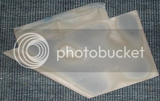
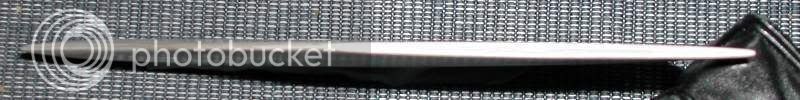
And here is a somewhat blurry photo of the same fin with the tip facing the camera. You can see the slight curve of the fin. I do not dare sand the edges much thinner, so those are pretty much as they will be on the finished one.
That's all for now. Hopefully I'll get the other two done tomorrow. Thursday is "going to town, getting paint"-day.
This oncoming weekend should include some serious building!
It felt like I had gotten stuck, not having any more primer at home. This morning I realized I could use some Plastic Padding (same stuff I used for the nosecone joint) on the fins. Hard to sand, but once done they would be smoooooth.
So before heading to work I put on a thin coating to all of the fins and let it harden.
As I knew there would be a few slow moments at work, I brought the fins with me
I managed to sand two of them today, and here are two pictures on one of them. I will sand them down a little bit further, but not much.
First; flat side (tape is for protecting the fin tabs):
And here is a somewhat blurry photo of the same fin with the tip facing the camera. You can see the slight curve of the fin. I do not dare sand the edges much thinner, so those are pretty much as they will be on the finished one.
That's all for now. Hopefully I'll get the other two done tomorrow. Thursday is "going to town, getting paint"-day.
This oncoming weekend should include some serious building!
.625" spacing; dope, that's what I remembered but didn't have my field notes and sketch in front of me. The Fin Gap is constant, or should I say as constant as things like this ever are
Dumas if you look at the photo of balltips models you'll see again the optical illusion of the gap narrowing toward the fin tip
I'm gonna have to look at the films of the Iris launch again Dumas.
Your the second person that has mentioned lighting both booster and sustainer at ignition, which isn't at all what I'm recalling from the launch films. Tiny Tim clustered booster burns out just before the rocket exits the top of the tower with upper stage Ignition of the sustainer just at that point. You can almost see the Iris hesitate before the motor comes up to power blowing tiny tim away. But before I can confirm this visual memory, I've gotta get the super-8 projector out and look at the film again. I may be thinkng of another sounding rocket of that same time frame? I'll let you know tomorrow
DumasBro2
Well-Known Member
- Joined
- Jan 26, 2009
- Messages
- 311
- Reaction score
- 0
OK, something to ponder overnight. From Report No. AST/E1R-13324, 18 April 1961 page 1 & 2: Iris is a two-stage, solid propellant rocket designed to be launched from a 160 foot, 4 rail tower of the type installed at Wallops Island, Virginia. Step one for the Iris is a separate thrust unit consisting of seven 4 inch diameter rocket motors which is used to increase the exit velocity from the tower. It is not mechanically attached to the Iris and falls away after the vehicle exits the tower. Thus, stage one operation utilizes both step one and step two thrust, while stage two requires only the second step motor. The ignition system incorporates a relay with a built-in time delay to insure that step one ignites at launch before step two does.
On page 31 the ignition schematic shows that relay mentioned has a 10ms time delay.
So not at the same time, but I would assume still on the rail If I read this correctly.
On page 31 the ignition schematic shows that relay mentioned has a 10ms time delay.
So not at the same time, but I would assume still on the rail If I read this correctly.
OK, something to ponder overnight. From Report No. AST/E1R-13324, 18 April 1961 page 1 & 2: Iris is a two-stage, solid propellant rocket designed to be launched from a 160 foot, 4 rail tower of the type installed at Wallops Island, Virginia. Step one for the Iris is a separate thrust unit consisting of seven 4 inch diameter rocket motors which is used to increase the exit velocity from the tower. It is not mechanically attached to the Iris and falls away after the vehicle exits the tower. Thus, stage one operation utilizes both step one and step two thrust, while stage two requires only the second step motor. The ignition system incorporates a relay with a built-in time delay to insure that step one ignites at launch before step two does.
On page 31 the ignition schematic shows that relay mentioned has a 10ms time delay.
So not at the same time, but I would assume still on the rail If I read this correctly.
Well Sorta, Did you notice that the booster in NOT physically attached to the sustainer? That 10ms plus the time it took for the relay to close, ignite the iris and come up to power looks like it's timed to happen about 15-20feet above the tower rails. I watched a 1959 and 1960 launch films in each the booster seperates before you see the sustain come up to full power..sorta of like the delay after you hear the launch control officer say 0 hitting the launch button and the time it take for the motor to actually start Composites all behave about the same way, really pretty neat way to get the Iris going
. So the Iris turely is a 2 staged combination. I also found my field notes and measurments on the fin gap. Their is a 3/16" (.1875") difference between the aft rear contact point of the rear shoe (.625" gap. and the forward edge of the front most shoe, Gap measured 7/16" (.4375") so my comment about the fin/body gap being a constant is incorrect. There is a slight reduction toward the leading edge of the fins.
Hope this helps, sorry for speaking before looking at the sheet.
Balltip
Well-Known Member
- Joined
- Feb 20, 2006
- Messages
- 988
- Reaction score
- 0
... I also found my field notes and measurments on the fin gap. Their is a 3/16" (.1875") difference between the aft rear contact point of the rear shoe (.625" gap. and the forward edge of the front most shoe, Gap measured 7/16" (.4375") so my comment about the fin/body gap being a constant is incorrect. There is a slight reduction toward the leading edge of the fins.
Hope this helps, sorry for speaking before looking at the sheet.
Aha! New info! I will use this on my build, good thing the fins are not in place quite yet!
Today has been a slow day building. Just sanded down the last fins, nothing more. Now I need some primer/filler.
Interesting information John. I have no doubt the video doesn't lie. Just posted that to show why I thought what I did. You have the video in electronic format? I'd love to see an Iris launch.
Dumas:
I have the very same wording on the flight report from June 1958 and october of 59. I was actully looking last night to see if any of the follow up reports give thrust levels for the "combined" stages at ignition. alas so far nothing shows in the data.
On the 1960 flight in slow motion it looks like the upper stage igniton is just a tad late with the sustainer, smoking all the way, almost coming to a complete stop in midair? than the motor really kicks in ( Huge Flame) and she's OUT A There in a hurry.
Oh man, Nope.. These Old super-8's were shot by one of the NRL crew at Wallops Island and given to my father (who worked on the project also for NRL) for me, the KID SPACE NUT...all of 10 at the time. I'm gonna try to some sort of way get them onto video and or DVD at some point.
Balltip
Well-Known Member
- Joined
- Feb 20, 2006
- Messages
- 988
- Reaction score
- 0
I am now reaching out to anybody that would be kind enough to help me print out a few sets of decals for this build! As this has been a quicker build than I ever imagined, I just now realized that I will need them quite soon.
I will supply you with a file (format of your choice within reason - I got Photoshop) and you print them out for me. I need good quality waterslide decals - Alps.
And naturally I'll pay you!
Pm me? Please? Somebody? Pllllllleeeeease? *doing my best Roger Rabbit imitation*
I will supply you with a file (format of your choice within reason - I got Photoshop) and you print them out for me. I need good quality waterslide decals - Alps.
And naturally I'll pay you!
Pm me? Please? Somebody? Pllllllleeeeease? *doing my best Roger Rabbit imitation*
DumasBro2
Well-Known Member
- Joined
- Jan 26, 2009
- Messages
- 311
- Reaction score
- 0
I just had a set of vinyl decals made for me by Dave Rose at Graphix & Stuff, very nice and great service. (Flew mine w/o decals last year) I'm sure he could scale down the files he has. (They have to be vector files)
John, if I'm ever in the DC area I'm looking you up to take a look at those films!
John, if I'm ever in the DC area I'm looking you up to take a look at those films!
Balltip
Well-Known Member
- Joined
- Feb 20, 2006
- Messages
- 988
- Reaction score
- 0
I got my previous decals for my IRIS's from Astronboy (Excelsior) and they are great quality!
However, when Estes made them they did not have the right font, so they went with something that looked a lot like the original.
Strangely enough, on this particular build I wont be satisfied unless I get as close as I can (given the limitations of time and knowledge).
Let me show you what I am talking about!
Here is the Estes font/decal for their BT50 IRIS

Here is the original (from the picture of "Tiny Tim")

Here is what we have come up with, using photoshop (what you see here is just a small jgp. The original is in PDF, and is 1,12 mb...)

If you start to compare the three fonts, you will see that the Estes type has each and every letter slightly wider than they should be. They also sport an "S" that is just not quite right.
We have been tweaking some fonts that we found, and have come up with what I personally feels has brought us closer to the original.
Ladies and gentlemen; opinions, please!
Edit: The observant might notice that I have edited the homemade logo a little. Now it sports somewhat narrower spacing between each individual letter. I think we are getting there!
However, when Estes made them they did not have the right font, so they went with something that looked a lot like the original.
Strangely enough, on this particular build I wont be satisfied unless I get as close as I can (given the limitations of time and knowledge).
Let me show you what I am talking about!
Here is the Estes font/decal for their BT50 IRIS
Here is the original (from the picture of "Tiny Tim")
Here is what we have come up with, using photoshop (what you see here is just a small jgp. The original is in PDF, and is 1,12 mb...)
If you start to compare the three fonts, you will see that the Estes type has each and every letter slightly wider than they should be. They also sport an "S" that is just not quite right.
We have been tweaking some fonts that we found, and have come up with what I personally feels has brought us closer to the original.
Ladies and gentlemen; opinions, please!
Edit: The observant might notice that I have edited the homemade logo a little. Now it sports somewhat narrower spacing between each individual letter. I think we are getting there!
Balltip
Well-Known Member
- Joined
- Feb 20, 2006
- Messages
- 988
- Reaction score
- 0
I got a set of IRIS decals left since I ordered mine for my BT60-build. One great thing is that I can use the "Atlantic Research Corporation" text (white) and the ARC logo (also white) as they are. They actually fit the BT70 better than they do the BT60 from a pure scale perspective! Only thing is that the ARC logo is 3mm too low/small. I'll settle for that though, as they are still pretty darn close. The text "Atlantic Research Corporation" actually fit almost perfectly, it is just 1mm off lengthwise (the BT60-decal is 92mm, and to be to scale it seems that it should be 93mm)!
Balltip
Well-Known Member
- Joined
- Feb 20, 2006
- Messages
- 988
- Reaction score
- 0
I have been offered help making the decals that I need, and I am so grateful!
I won't be mentioning names since I do not know if my helper want to go public, but it is a member here on TRF.
I can also say that I will put together a CD once this build is done, containing all the data I got. Pictures, drawings, measurements, the PDF with the resurrected IRIS logo - the works.
Anybody wanting this info should contact me through email and I'll get one of those Cd's to you for free. But hold that email until I say I got the CD ready for shipment!
Yeah, I know postage is expensive. But I have gotten so much from this forum that this is the least I can do! (I even got a set of decals in my mail today, for another build that I am about to start, a scifi build. I got them for free, sent to me from the other side of the globe...!)
Well, back to the build...
Today I have been at it again - if only a little. I got three builds going right now, and I spent most of today's building time on the other two.
What has been done with this one is that I have painted the fins red (yes, I do that in advance - you will see why later) and have filled spirals, sanded down and primed the forward BT.
Tonight, after getting back from a fishing trip on the lake (gf caught a small European "bass", but that was pretty much it), I sat down and started to add details to the aft BT. Here you see my efforts so far:
I will give you an update tomorrow (why is it that one needs to sleep during the weekends??? I wanna build!!!!! Oh, sorry.... I'll stop screaming now)
Balltip
Well-Known Member
- Joined
- Feb 20, 2006
- Messages
- 988
- Reaction score
- 0
I should also add that I spent a good portion of the time "in between customers" yesterday sanding down the nose cone completely!
It looked great after I had clear coated it (beginning of this thread) but after a few days the spirals in the added piece of tubing began to show. And it just kept getting worse!
I had tried a new method of filling the spirals, and that was to strenghten the wall putty I used with thin CA.
Something happened in the process, and the spiral ended up showing off in a very bad way.
Lesson hopefully learned, and problem hopefully solved.
Balltip
Well-Known Member
- Joined
- Feb 20, 2006
- Messages
- 988
- Reaction score
- 0
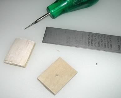
Today I have begun making the fin clamps. I got myself some wood from the wood shed and as I was looking for something that is soft, easy to work with and has a low level of grain I got a piece of alder.
Then I turned on my mill...
It is hard working with such small details in a mill, even if it is a mill made for precision work in metal. But so far the first few fin clamps has turned out ok.
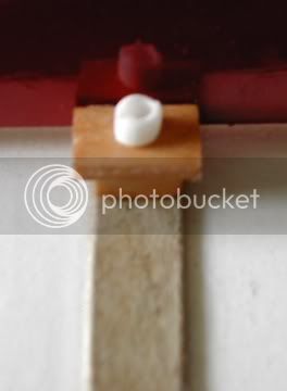
The picture is showing a fin clamp that is 7mm wide at the top, and 5mm at the base, thus the "lips" are 1mm. The "hex head" screw is a piece of cut off plastic straw.
It is not glued in place, I just put it there to get a feel for what it might look like once I finish this build (I think that "screw" actually also needs a washer).
You will have to imagine the band and clamp painted white...
There won't be much more work done today, except for priming the aft BT.
I am quite beat, as I did not sleep much last nite due to some cough.
Then I turned on my mill...
It is hard working with such small details in a mill, even if it is a mill made for precision work in metal. But so far the first few fin clamps has turned out ok.
The picture is showing a fin clamp that is 7mm wide at the top, and 5mm at the base, thus the "lips" are 1mm. The "hex head" screw is a piece of cut off plastic straw.
It is not glued in place, I just put it there to get a feel for what it might look like once I finish this build (I think that "screw" actually also needs a washer).
You will have to imagine the band and clamp painted white...
There won't be much more work done today, except for priming the aft BT.
I am quite beat, as I did not sleep much last nite due to some cough.
Balltip
Well-Known Member
- Joined
- Feb 20, 2006
- Messages
- 988
- Reaction score
- 0
I thought I could as well post a picture of the assembly "process" of the fin clamps.
Here you see a few of them as the CA is drying. Process is pretty straightforward: Sand each individual fin clamp until it is smooth (sandpaper style nail file), dip cut off plastic straw - "bolt head" - in CA and using tweezers place it onto the fin clamp.
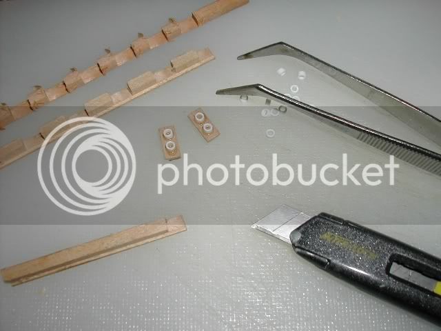
To the top left are the "raw" fin clamps as they look after milling. You can see that I made them as lengths.
Cutting them apart is easy, all it takes is a sharp blade. Gotta love that Stanley knife!
I have never owned an Exacto knife, and I doubt I'll ever get one. If you see one of those Stanley knives - give it a try! You just have to snap off the blade once it is dull and you got a fresh one. There are several sizes of the same style knife, I'd recommend the smallest one for modeling and the larger one for your tool box.
Here you see a few of them as the CA is drying. Process is pretty straightforward: Sand each individual fin clamp until it is smooth (sandpaper style nail file), dip cut off plastic straw - "bolt head" - in CA and using tweezers place it onto the fin clamp.
To the top left are the "raw" fin clamps as they look after milling. You can see that I made them as lengths.
Cutting them apart is easy, all it takes is a sharp blade. Gotta love that Stanley knife!
I have never owned an Exacto knife, and I doubt I'll ever get one. If you see one of those Stanley knives - give it a try! You just have to snap off the blade once it is dull and you got a fresh one. There are several sizes of the same style knife, I'd recommend the smallest one for modeling and the larger one for your tool box.
Wow Balltip!
the fin clamp details are coming along GREAT! very nicely done.
Dumas:
I'll have to look them up, Flat head (Slotted) but I can't for the life of me remember what size.
Edit!!!!
Flat Head Slotted .23" dia head, 1.25" oc. around 39-7/16" circum. (approx. 12.55" diameter) nosecone 80" long to first step of 3.808" Collar.
I really need to scan these field sketches and notes for you guys. I'm not sure if they will help or cause more head scratching LOL. But I'm gonna try and see if I can get it in a small enough PFD to upload in just a couple minutes.
Balltip
Well-Known Member
- Joined
- Feb 20, 2006
- Messages
- 988
- Reaction score
- 0
Sorry dumas, I got nothing regarding the screws on the front band. Hopefully micro can dig something up for us!
Thanks micromesiter! It is not difficult making those clamps, just takes some time (and a mill, preferably... LOL!)
I had to redo the clamps a little. It turned out i had been a little too careful when dipping the "screw heads" into the CA. I had not gotten enough adhesion to keep some of the real firmly in place!
So what I did was that I stuck them all in a small plastic can, sprayed a light mist of CA accelerator into the can and put the lid on for about 20 minutes. After that I let the vapours out (outside) and started to add CA to the screw heads - filling the hole down the middle.
To avoid the holes getting overfilled I just dabbed a thin piece of paper towel to soak up excessive CA. As I had "primed" the clamps with accelerator the CA hardened in about two or three minutes, despite that what I did was to fill the inside of the straws/screw heads.
Upon hardening, the CA now forms a sort of glue rivets inside the straws and they should not easily come off.
That is what I done today, but I guess any progress is good progress, eh?
Well I got the front and back scanned in pdf formate, but it's still over 250kbs so If you'd like me to e-mail these notes drop me your e-mail addresses to [email protected] Sorry for the inconvenience but I just can't seem to get the dumb thing any smaller
does have a lot of other info. from a very long day of measureing and detailing the last known example of the Iris.
I also corrected the previous post about the nosecone screws.
Hope this helps.
does have a lot of other info. from a very long day of measureing and detailing the last known example of the Iris.
I also corrected the previous post about the nosecone screws.
Hope this helps.
Balltip
Well-Known Member
- Joined
- Feb 20, 2006
- Messages
- 988
- Reaction score
- 0
Today work has been getting in the way of building. Oh well, that is a good thing as I am now running my own business!
The only progress on the build has been this little thing showing in the photo below:
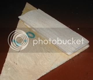
The balsa strip you see is 2" long, and the entire thing will be trimmed down, cut in two and used as anchor points inside the BT for the rail button screws. The balsa has been sanded to fit nicely against the inside curve of the BT. This way I hope to keep the BT nice and round even after I have tightened down the rail button screws! The ply is there to give the screws somethiong to "bite" at.
The only progress on the build has been this little thing showing in the photo below:
The balsa strip you see is 2" long, and the entire thing will be trimmed down, cut in two and used as anchor points inside the BT for the rail button screws. The balsa has been sanded to fit nicely against the inside curve of the BT. This way I hope to keep the BT nice and round even after I have tightened down the rail button screws! The ply is there to give the screws somethiong to "bite" at.
Balltip
Well-Known Member
- Joined
- Feb 20, 2006
- Messages
- 988
- Reaction score
- 0
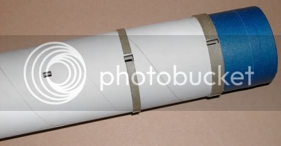
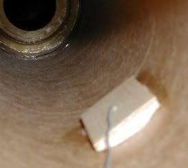
So it was time to install the stiffeners for the rail button screws...
First I trimmed them to shape. I also poked a small hole through them to help me place them correctly inside the airframe.
I then used that little hole to guide them to where I wanted them to sit. You see the thin steel wire acting as a guide here. This is the front one, but the aft one was pretty much done the same way (even though it was much harder getting the aft one in place, as the BT60 in the aft got in the way. In the end it worked out though).
Sorry, picture is a bit out of focus.
Having dealt with these details, I again turned to the exterior of the rocket. Having worked so much with the fins and the fin bands, I felt it was time I put in some work regarding the front band that runs round the BT just behind the NC.
Having received Johns field notes it was clear to me that that band looked a bit differently than I had imagined. Nothing is like getting reliable data!
I made some calcs and it turned out I should start out by adding a band that is 8,5mm wide to run all the way around the BT. It was an easy job (good that something turned out to be easy for a change LOL!).
Glue is still drying as I write this.
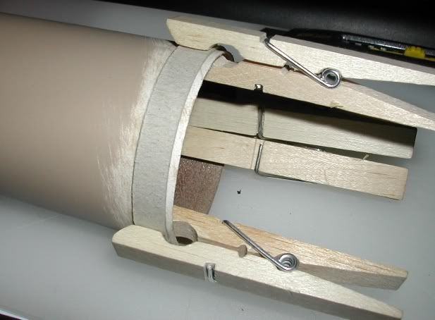
Now I might have misunderstood Johns notes, but if I have interpreted them right, the shape of the front BT band should be like this once finished (this simple scetch is greatly exaggerated and not to scale)
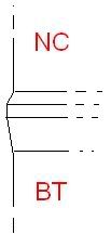
So more work will have to be done before things look like they should. But I do not mind!
First I trimmed them to shape. I also poked a small hole through them to help me place them correctly inside the airframe.
I then used that little hole to guide them to where I wanted them to sit. You see the thin steel wire acting as a guide here. This is the front one, but the aft one was pretty much done the same way (even though it was much harder getting the aft one in place, as the BT60 in the aft got in the way. In the end it worked out though).
Sorry, picture is a bit out of focus.
Having dealt with these details, I again turned to the exterior of the rocket. Having worked so much with the fins and the fin bands, I felt it was time I put in some work regarding the front band that runs round the BT just behind the NC.
Having received Johns field notes it was clear to me that that band looked a bit differently than I had imagined. Nothing is like getting reliable data!
I made some calcs and it turned out I should start out by adding a band that is 8,5mm wide to run all the way around the BT. It was an easy job (good that something turned out to be easy for a change LOL!).
Glue is still drying as I write this.
Now I might have misunderstood Johns notes, but if I have interpreted them right, the shape of the front BT band should be like this once finished (this simple scetch is greatly exaggerated and not to scale)
So more work will have to be done before things look like they should. But I do not mind!
geof
Well-Known Member
- Joined
- Feb 15, 2009
- Messages
- 1,277
- Reaction score
- 0
This is the first time I have checked out this thread because "scale" is usually not my thing, but I've gotta say.....WOW! What an amazing build, with so many new (to me) techniques to consider. I can't imagine turning my own rail buttons. Great job, balltip, you've really given me a lot to think about with all your careful craftsmanship. Good luck with the rest of the build.
Geof
Geof
So it was time to install the stiffeners for the rail button screws...
First I trimmed them to shape. I also poked a small hole through them to help me place them correctly inside the airframe.
I then used that little hole to guide them to where I wanted them to sit. You see the thin steel wire acting as a guide here. This is the front one, but the aft one was pretty much done the same way (even though it was much harder getting the aft one in place, as the BT60 in the aft got in the way. In the end it worked out though).
Sorry, picture is a bit out of focus.
Having dealt with these details, I again turned to the exterior of the rocket. Having worked so much with the fins and the fin bands, I felt it was time I put in some work regarding the front band that runs round the BT just behind the NC.
Having received Johns field notes it was clear to me that that band looked a bit differently than I had imagined. Nothing is like getting reliable data!
I made some calcs and it turned out I should start out by adding a band that is 8,5mm wide to run all the way around the BT. It was an easy job (good that something turned out to be easy for a change LOL!).
Glue is still drying as I write this.
Now I might have misunderstood Johns notes, but if I have interpreted them right, the shape of the front BT band should be like this once finished (this simple scetch is greatly exaggerated and not to scale)
So more work will have to be done before things look like they should. But I do not mind!
You didn't misunderstand my notes Balltip.
Don't forget there is another welded raiser of similar detail near the extreme aft end of the motor casing under the rear most fin mounting clamps.
I found these welded casing reinforcments fascinating as they don't really show up on the AR or other vehicle drawings well as all.
Balltip
Well-Known Member
- Joined
- Feb 20, 2006
- Messages
- 988
- Reaction score
- 0
You didn't misunderstand my notes Balltip.
Don't forget there is another welded raiser of similar detail near the extreme aft end of the motor casing under the rear most fin mounting clamps.
I found these welded casing reinforcments fascinating as they don't really show up on the AR or other vehicle drawings well as all.
Aha! That is what can be seen in the pictures you have sent me! I have been unsure about what that was, but now as you mention it, it becomes quite apparent. Thanks!
(Darn! Now I will have to reconstruct the aft end a bit. It is doable, but I felt good thinking I was "all done" with that part... LOL! Oh well, I'll wing it as close as I can withou having to tear off that aft band completely. Should end up quite true, really.)