


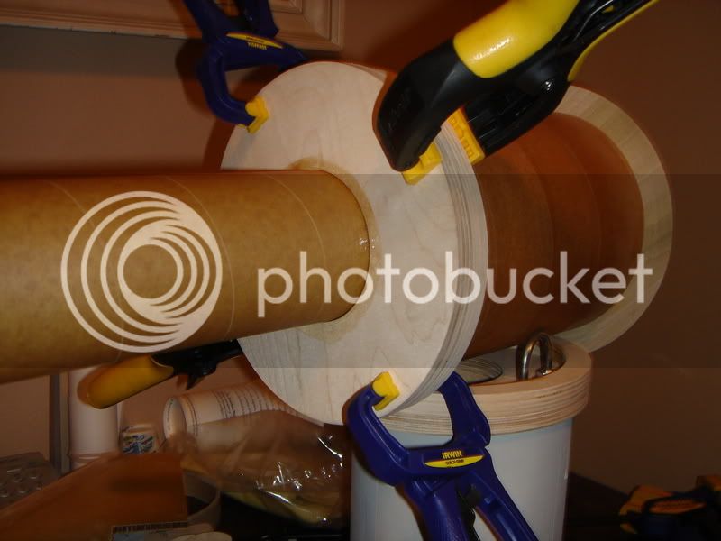
Here's a shot of one of the av-bay pods partially inserted into the av-bay, and another shot with the sled partially inserted into the pod...


Originally posted by SteelyEyed
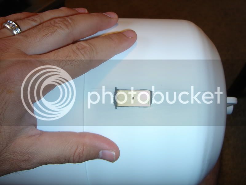
I plan to create my static vent ports by drilling through the forward airframe and main coupler (the av-bay resideds inside the main coupler) at 3 locations that will expose the entire av-bay volume to atmospheric pressure and two of those holes will be aligned to allow access to the Newton's 3rd screw switches so I can insert a ball-end allen wrench to turn the screw switches to arm the altimeters. I intend to cut over-sized holes in the walls of the two pods and tubes that hold the altimeters so that both altimeters will be open to the inside volume of the av-bay. I think I explained that right...
Originally posted by uncle_vanya
A word of caution here and a disclaimer. First the disclaimer: I am not an expert on this subject but I have practical experience with the failure mode I am about to describe.
Caution: With the design that you are using for the screws if for any reason your main should not fully deploy and the rocket lands hard - your screw switches may dislodge from where you aligned them with the holes. This makes disarming the live charges scary.
Originally posted by Ryan S.
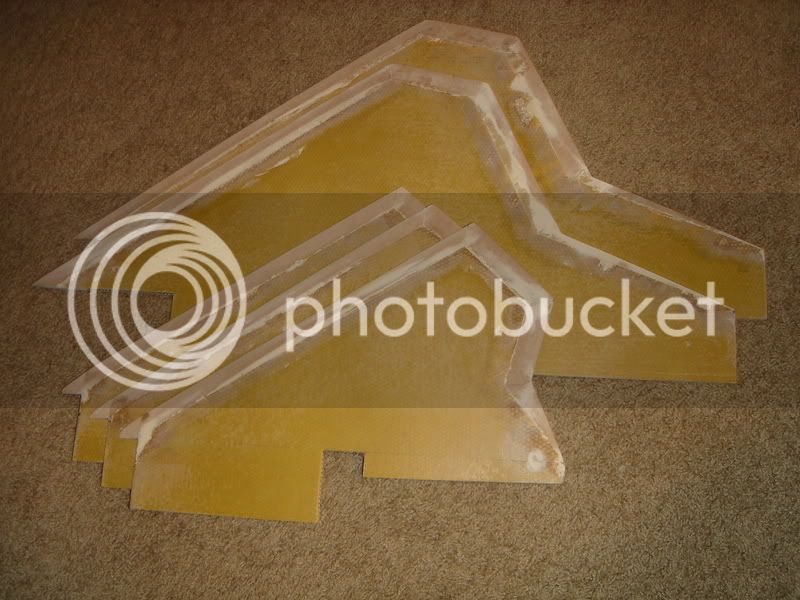
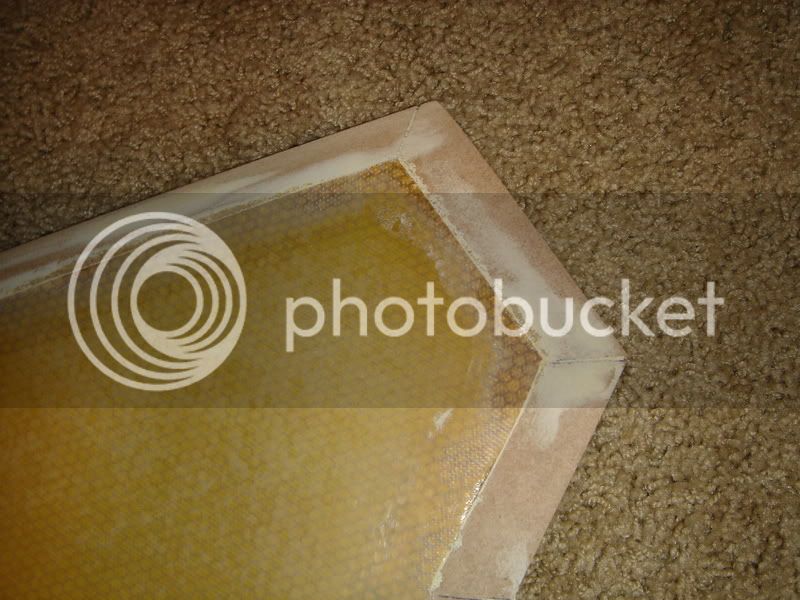
I am surprised at the decision to use MDF for the edging, I would think you would want something a little more durable so as to withstand landings and the unavoidable bumps the rocket will encounter during flight and transport.
Are you going to glass these fins or the leading/trailing edges so that your bevels dont get ruined?
SteelyEyed
No update on this more recently???
")
I would have loved to see this one kitted. - Again
Is Giant Leap still around? They have a website with old pages that include the Nuclear Sledgehammer.
Is Giant Leap still around? They have a website with old pages that include the Nuclear Sledgehammer.
When you finish, could you post your file for comparison?
I ordered some tubing from them this year.
Enter your email address to join: