Scratch-built 4" AQM-37 Jayhawk

The Rocketry Forum

Help Support The Rocketry Forum:

This site may earn a commission from merchant affiliate links, including eBay, Amazon, and others.

gboxwood

Active Member
TRF Supporter
Joined
Jul 4, 2023
Messages
30
Reaction score
19
Location
The Netherlands
I have a thing for the Jayhawk design and I came across a vintage Estes PRO Series kit just recently.

Needless to say, it sparked my desire to design and build a bigger Jayhawk and for the time being, I decided to stick to a 4” airframe (glassed LOC tubing).

One of the first things I had to decide was the motor mount size, both the 38mm and 54mm options fit and I eventually selected the latter as it simply gives you more engine options.

I’m not a super-scale freak and this build shall be regarded as such, i.e., a sporty rendition of the Jayhawk which is still based on tracing blue prints of the full scale design (information which is readily available on the internet).

One of the main design parameters is the nosecone as it will determine the airframe tubing length. For this build, I had a Giant Leap Rocketry pinnacle nosecone “from the past” (the newer ones are even longer) and I based the overall design on this specific component.

I use Rhinoceros for the 3D modeling, I find it a good compromise software to achieve decent results in little time. I also need it to generate the templates for the laser cutter and any geometry to be 3D printed at a later stage.

Capture by Giacomo Bosso, su Flickr

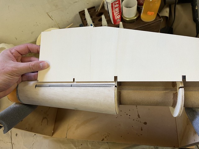
The following picture shows the laser cut parts, they are all 3mm lite-ply and they turned out very accurate. The top 3 centering rings are 6mm thick and I laminated them together to achieve that thickness.

Senza titolo by Giacomo Bosso, su Flickr
 

The motor mount tube​

The motor mount is marked first, then the Giant Leap Slimline retainer is bonded to it and finally the centering rings are slid over the tube, positioned by means of the wings and epoxied in place.

Senza titolo by Giacomo Bosso, su Flickr

At this time, I do not glue the wings in, I just use them as “spacing devices” for the centering rings.

Senza titolo by Giacomo Bosso, su Flickr

The motor tube assembly requires some additional work, namely: the parachute attachment point, the rail guides blocks and the conical boat tail.
 

The boat tail​

The boat tail requires some more work. First, the stringers are glued into place. Please note the aft end of the stringer needs to be shaped like a wedge to fit in the slot: the slot is not full depth due to the fact that the ring is very minimal if a 54mm motor tube is used. The stringers are 4x4mm square balsa.

Senza titolo by Giacomo Bosso, su Flickr

Also note that some stringers are placed to the sides of the wing tab which extends into the boat tail and also behind it. Those stringers do not have slots cut for them into the centering rings and they need to be cut more accurately and glued in place.

Senza titolo by Giacomo Bosso, su Flickr
 
Next us is the template for the conical transition. I tried different approaches and I landed on a mix of math, CAD and practical adjustments. I decided to use 1mm thick balsa to sheet the boat tail, plus 2 layers of fiberglass. I always try to prepare the sheeting material so I have it in one single piece for the application.

Senza titolo by Giacomo Bosso, su Flickr

Senza titolo by Giacomo Bosso, su Flickr

Senza titolo by Giacomo Bosso, su Flickr
 
I join balsa sheets with aliphatic glue making sure the edges are tight against one another. Then I cut it to shape and wrap it around the transition.

Senza titolo by Giacomo Bosso, su Flickr

Senza titolo by Giacomo Bosso, su Flickr

I find it easier to start and end on a stringer and glue the first edge with CA so that it stays in place while pull the rest around. Before doing that, all the stringers and centering rings receive a generous amount of aliphatic glue.

Senza titolo by Giacomo Bosso, su Flickr
 
Some sanding is required once the glue has dried but care shall be taken in not sanding through the sheeting material (which is very thin). Next up, glassing the transition to strengthen it a bit more. I used two layers of 200 g fiberglass for this purpose.

Senza titolo by Giacomo Bosso, su Flickr

Senza titolo by Giacomo Bosso, su Flickr
 
Please note that both the retainer and the portion of the centering ring that will be inserted in the airframe tube were masked prior to glassing. This will help in cleaning them before they are assembled into the 4” tube.

Senza titolo by Giacomo Bosso, su Flickr

Senza titolo by Giacomo Bosso, su Flickr

After the glassing is done, the tape is removed and some sanding will be required to clean the centering ring.

Senza titolo by Giacomo Bosso, su Flickr
 
The left-over tube section is cut 30mm long to create a trust ring that will sit on top of the upper centering ring.

Senza titolo by Giacomo Bosso, su Flickr

In order to do so, its OD shall be reduced by cutting a certain length out. The new ring is strengthened by an internal layer of fiberglass.

Senza titolo by Giacomo Bosso, su Flickr

Please note the thrust ring bottom edge shall be cut to fit around the G10 reinforcement plate.

Senza titolo by Giacomo Bosso, su Flickr

That’s pretty much it for the main airframe section.
 

Vertical fins​

I debated a bit about how to give the flying surfaces a decent look, both in terms of scale appearance, strength and aerodynamics.

I decided to start with a flat piece of lite-ply and strengthen the edges with 3mm diameter carbon rods. In the end, these will be the landing surfaces of the model.

Please note the sequence with which the rods are added to the outline of the vertical fins.

Senza titolo by Giacomo Bosso, su Flickr

Senza titolo by Giacomo Bosso, su Flickr

Senza titolo by Giacomo Bosso, su Flickr

Senza titolo by Giacomo Bosso, su Flickr
 
Then, the outer side only gest a thickening treatment by means of 4mm balsa: the balsa sheet is glued in place, it is cut to match the contour of the fins and then the leading and trailing edges are shaped accordingly. I used a straight line offset 1” from the outer edge as an arbitrary rule.

Senza titolo by Giacomo Bosso, su Flickr

Senza titolo by Giacomo Bosso, su Flickr
 
Then they get 2 layers of 200 grams fiberglass to seal it and strengthen the balsa.

One layer of fiberglass will also be used on the inside surface to seal the lite-ply and the carbon rods. The inner side of the fin however, is left flat.

Senza titolo by Giacomo Bosso, su Flickr

These surfaces are much easier to finish while not being assembled to the rest of the airframe. I therefore primed, filled and sanded a couple of times until satisfied with the overall smoothness.

Senza titolo by Giacomo Bosso, su Flickr

Senza titolo by Giacomo Bosso, su Flickr

Senza titolo by Giacomo Bosso, su Flickr
 

Wings​

The wings are initially used to align the centering rings as they are glued to the motor mount tube. Then the boat tail is done and eventually the focus turns to the wings.

The wings’ leading edges are shaped by means of 3 mm diameter carbon rods CA’d in place. They require less work than the vertical fins in this regard.

Senza titolo by Giacomo Bosso, su Flickr
 
The main airframe and the wings are dry fitted to the motor mount and the airframe is used to mark the location of the balsa cores that will be added to the wings plywood base material.

Senza titolo by Giacomo Bosso, su Flickr

Please note the chamfers on tab’s slots: they will make sure you have the best possible fit between the wings and the motor mount tube with the centering rings.

Senza titolo by Giacomo Bosso, su Flickr

The markings are used to glue the 4 mm thick balsa cores to both sides of the wings. It is worth noting that there will be a 100 mm wide piece and a special, thin wedge element will be used to fill the gap towards the boat tail.

Senza titolo by Giacomo Bosso, su Flickr

Senza titolo by Giacomo Bosso, su Flickr
 
The wings to airframe fillets are created at the same time, I use thickened laminating resin for this step and it allows me to lay down fillets at the same time because the bonding material will not run.

Before proceeding with the glassing, the airframe to boat tail transitions requires some attention.

Senza titolo by Giacomo Bosso, su Flickr

Senza titolo by Giacomo Bosso, su Flickr

Senza titolo by Giacomo Bosso, su Flickr
 
Once smooth enough, it is time to lay two layers of fiberglass over the wings. The first layer will go tip-to-tip, the second layer goes over the wings (to protect the soft balsa core) and over the fillet. It does not need to wrap the airframe tube as well because the tube has been previously glassed on its own.

Senza titolo by Giacomo Bosso, su Flickr

Senza titolo by Giacomo Bosso, su Flickr
 
The last step in airframe preparation is coating it with a specially formulated resin, a product used in 3D printing and supplied by Smooth On. This is a great resin that cures quick enough and it is very easy to sand. It will fill in the fiberglass weaves much better than any filler out there.

Senza titolo by Giacomo Bosso, su Flickr

Senza titolo by Giacomo Bosso, su Flickr
 
Back
Top