


mdoering
Well-Known Member
- Joined
- Aug 31, 2012
- Messages
- 516
- Reaction score
- 1
Welcome to my first build thread! After getting back in to rocketry about two months ago after a 15 year hiatus I caught he MPR/HPR bug BAD! I flew my L1 at my first club launch on an Estes Pro Series II Leviathan using an H165R-M and I was hooked! I quickly set about planning my L2 build.
The kit I chose for my L2 is the Madcow AGM-33 Pike. Because I planned on this being for L2 flights, and the 4" diameter airframe left plenty of room, I opted to go with a 54mm motor mount in place of the stock 38mm. Mike at Madcow was great to work with during the ordering process and provided stellar pre-sales phone support. I'll definitely be back for more!!
With kit in hand, the obvious first place to start is a dry assembly. Here it is in all it's fresh out of the package goodness, and wait, who's that handsome model? :lol: :eyeroll:

As I'm sure you noticed from the dry fit, upgrading the motor mount does not mean Mike sends the pre-cut fins into Santa's workshop for resizing... We'll tackle that in a minute... But first, let's get that motor mount built!
The first step here is to peel off that groovy phenolic paper to expose the fresh fuzzy virgin tubing underneath to allow full penetration of the epoxy

I didn't get photos of putting on the centering rings, but you place each one 1/2" from either end of the tubing ensuring that they won't interfere with the fins.
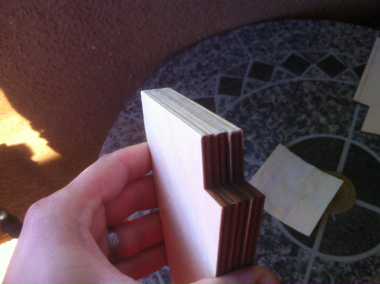
Now about them fins! I took 5/16" off of each fin tab. This allowed the fin to make contact with the motor tube, and allowed the fin root to seat fully on the exterior of the airframe.

One down, five to go!
That's looking better already! Note the smoooooooooooooth surface left behind by that sweet little Japanese style saw!
With all the fin tabs cut down to size, I used my super ADD skills to change my focus to another part of the build... The avionics bay! I assembled the sled with some epoxy and threw some fillets on there to make it look so purdy only a deranged rocketphile could appreciate it.


With that set aside to cure I went back to the fins. I roughed up the exterior of the airframe using a rock (practically, it was really a 20 grit sanding/grinding disk pad) to improve adhesion.


With that done, the fins were attached and epoxy was injected using the syringe pictured above in conjunction with some plastic tubing to give me extreme control over where the epoxy ended up in the airframe. I also "tacked" it in place in several spots along the exterior of the airframe to hold it in place until the epoxy set so I could do the external fillets.
The fillets were masked, filled, and shaped


Then after a few minutes the masking tape was removed and final detail shaping done before full setting of the epoxy occurred.

While those set up, I switched focus back to the avionics again for a bit. I recently picked up a Blacksky AltAcc 2A altimeter from a fellow TRFer and set out to get it mounted in the avionics bay and start getting it wired up.


You'll have to excuse the extra long green wires and random LED on the terminal strip, before I finalized placement of things I wanted to ensure I had plenty of slack on the wires. They will soon be bundled with the rest of 'em and the LED will be mounted on the avionics bay exterior sleeve. (A 1" band of airframe glued in place around the center line of the avionics bay) The "Remove Before Flight" pin activates a switch for arming the altimeter bypassing the built in screw switch (who wants to have to take a screw driver out to the pad?)


That brings us to our current state and most recent dry assembly. Here she is in all her unpainted glory

So what's next?
I need to finish the avionics, I'm going to be adding a key switch to the avionics bay ring to allow me to turn the altimeter on and off without disassembling the rocket. I also need to add the static ports to the avionics bay ring, and attach the charge wells to each end.
I need to drill holes in the forward airframe through the avionics bay for insertion of tee nuts from the interior of the avionics bay. This will allow me to use screws to keep the avionics bay attached to the aft end of the forward airframe section during separation and recovery. The plan is to have the drogue chute in the aft airframe, and the main in the forward airframe. As such, I'll be drilling through the forward end of the forward airframe into the shoulder of the nose cone for shear pins. I have picked up some thin brass strips to be used as airframe and nose cone shoulder reinforcement and improved shear pin cutting.
Once this is done she should be ready for paint and decals! I plan on flying my L2 with a CTI 54mm 6G K260CL Long Burn motor. With 8.5 seconds of burn time it should put this rocket to about 9,000' AGL under perfect conditions.
The kit I chose for my L2 is the Madcow AGM-33 Pike. Because I planned on this being for L2 flights, and the 4" diameter airframe left plenty of room, I opted to go with a 54mm motor mount in place of the stock 38mm. Mike at Madcow was great to work with during the ordering process and provided stellar pre-sales phone support. I'll definitely be back for more!!
With kit in hand, the obvious first place to start is a dry assembly. Here it is in all it's fresh out of the package goodness, and wait, who's that handsome model? :lol: :eyeroll:
As I'm sure you noticed from the dry fit, upgrading the motor mount does not mean Mike sends the pre-cut fins into Santa's workshop for resizing... We'll tackle that in a minute... But first, let's get that motor mount built!
The first step here is to peel off that groovy phenolic paper to expose the fresh fuzzy virgin tubing underneath to allow full penetration of the epoxy
I didn't get photos of putting on the centering rings, but you place each one 1/2" from either end of the tubing ensuring that they won't interfere with the fins.
Now about them fins! I took 5/16" off of each fin tab. This allowed the fin to make contact with the motor tube, and allowed the fin root to seat fully on the exterior of the airframe.
One down, five to go!
That's looking better already! Note the smoooooooooooooth surface left behind by that sweet little Japanese style saw!
With all the fin tabs cut down to size, I used my super ADD skills to change my focus to another part of the build... The avionics bay! I assembled the sled with some epoxy and threw some fillets on there to make it look so purdy only a deranged rocketphile could appreciate it.
With that set aside to cure I went back to the fins. I roughed up the exterior of the airframe using a rock (practically, it was really a 20 grit sanding/grinding disk pad) to improve adhesion.
With that done, the fins were attached and epoxy was injected using the syringe pictured above in conjunction with some plastic tubing to give me extreme control over where the epoxy ended up in the airframe. I also "tacked" it in place in several spots along the exterior of the airframe to hold it in place until the epoxy set so I could do the external fillets.
The fillets were masked, filled, and shaped
Then after a few minutes the masking tape was removed and final detail shaping done before full setting of the epoxy occurred.
While those set up, I switched focus back to the avionics again for a bit. I recently picked up a Blacksky AltAcc 2A altimeter from a fellow TRFer and set out to get it mounted in the avionics bay and start getting it wired up.
You'll have to excuse the extra long green wires and random LED on the terminal strip, before I finalized placement of things I wanted to ensure I had plenty of slack on the wires. They will soon be bundled with the rest of 'em and the LED will be mounted on the avionics bay exterior sleeve. (A 1" band of airframe glued in place around the center line of the avionics bay) The "Remove Before Flight" pin activates a switch for arming the altimeter bypassing the built in screw switch (who wants to have to take a screw driver out to the pad?)
That brings us to our current state and most recent dry assembly. Here she is in all her unpainted glory
So what's next?
I need to finish the avionics, I'm going to be adding a key switch to the avionics bay ring to allow me to turn the altimeter on and off without disassembling the rocket. I also need to add the static ports to the avionics bay ring, and attach the charge wells to each end.
I need to drill holes in the forward airframe through the avionics bay for insertion of tee nuts from the interior of the avionics bay. This will allow me to use screws to keep the avionics bay attached to the aft end of the forward airframe section during separation and recovery. The plan is to have the drogue chute in the aft airframe, and the main in the forward airframe. As such, I'll be drilling through the forward end of the forward airframe into the shoulder of the nose cone for shear pins. I have picked up some thin brass strips to be used as airframe and nose cone shoulder reinforcement and improved shear pin cutting.
Once this is done she should be ready for paint and decals! I plan on flying my L2 with a CTI 54mm 6G K260CL Long Burn motor. With 8.5 seconds of burn time it should put this rocket to about 9,000' AGL under perfect conditions.


