Clusterphiliac
Active Member
- Joined
- Sep 2, 2013
- Messages
- 39
- Reaction score
- 0
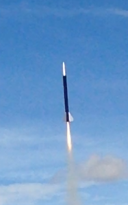
Not really sure what to say as an introduction, but here's my Level 1 Certification build. As a bit of personal background, I've been building rockets since I was twelve, but now I'm finally making the leap to high power. I'm a college sophomore, building this with my school's rocketry club.
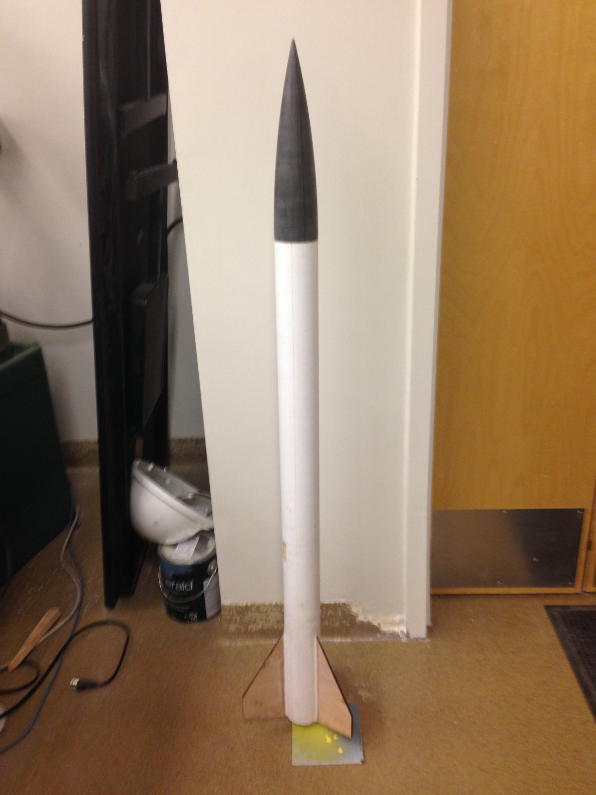
The rocket, like most cert builds, is a fairly standard 3FNC. It's 3" diameter and 54.5" tall (not counting about 3/8" of overhanging motor retainer), with a 38mm motor mount. The thing was first designed several years ago, but has gone through a few iterations before I actually ordered parts.
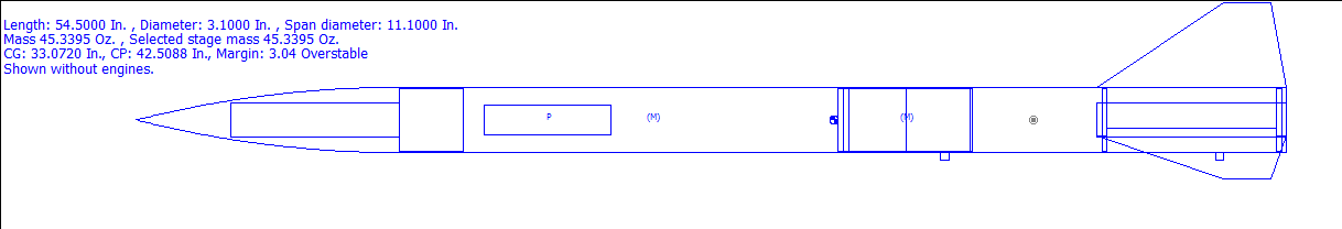
The design - not every component shown.
The airframe and motor mount are standard LOC cardboard tubing, but the coupler is blue tube, which should be a bit stiffer. The fins, bulkheads, and main centering rings are 1/4" plywood, and some minor components are 1/8".
Now, this rocket has a few unusual features. First, the avionics bay is built into the nose cone, and is a "sledless" design. There are three small bays: a pair of 29mm bays sized to accomodate a Raven 3 in a Featherweight 29mm Avbay kit, and a longer BT-60 sized bay in the front for any radio, GPS, or acoustic tracking devices that might be installed. It is dual-deploy; the apogee charge ejects the parachute and nose cone, and the main charge is located in an Archetype Rocketry Cable Cutter. In flight, the airframe never actually separates in the middle; the upper airframe is connected with Apogee's removable rivets. Technically it isn't zipper-proof, but the only part that could ever zipper is the upper airframe, which is very easy to replace.
Now, on to the build.
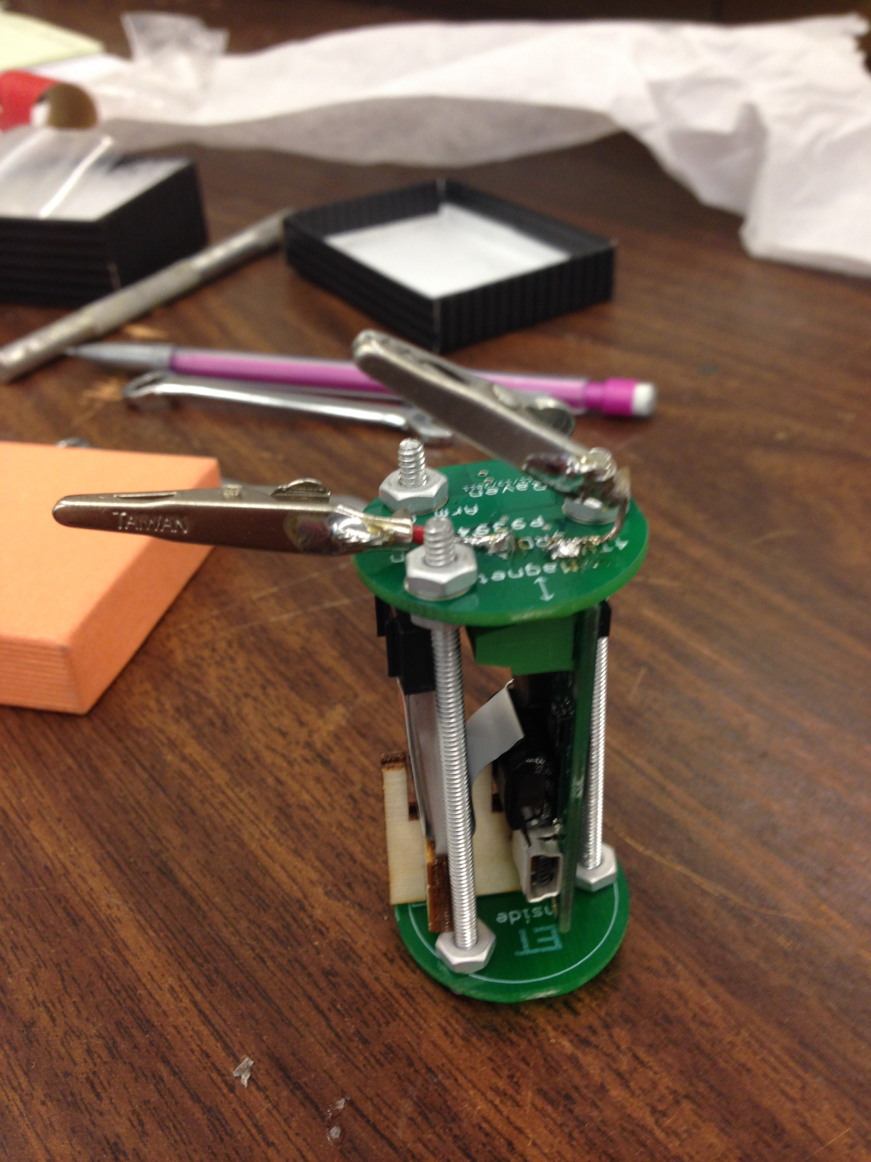
The first major part I put together is the avionics bay. As previously mentioned there are two altimeter bays (allowing for an upgrade to redundant altimeters), and a tracker/everything else bay. The tubes are just plain old thin-walled "Estes Grade" cardboard. The rings are 1/8" plywood, with the rear ring actually being two rings - one fitting the airframe, one fitting the nose cone shoulder - sandwiched together. The whole thing attaches to the nose cone with a pair of 1/4-20 threaded rods. A 6-32 machine screw and washer fit into a threaded standoff (bottom of the image), holding the altimeters in place.
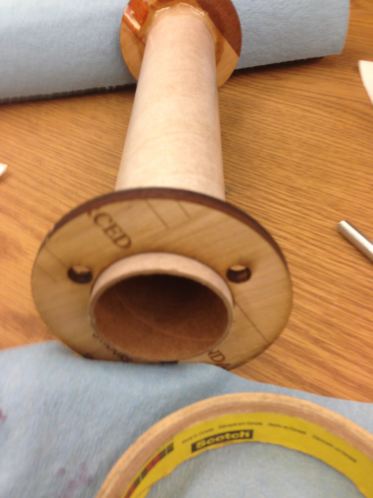
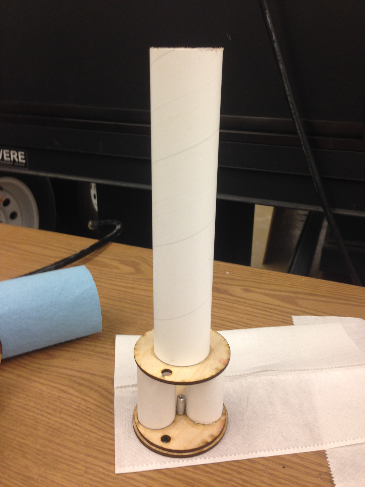
Meanwhile, here's the motor mount. 9" of LOC 38mm MMT tube with 1/4" plywood centering rings. The rings are in contact with the ends of the fin tabs, providing a very strong assembly. The rear CR is unattached; it goes in later to allow for internal fillets on the fins. The three holes in it are for threaded 6-32 standoffs. As with the altimeter bays, screws and washers are used for motor retention.
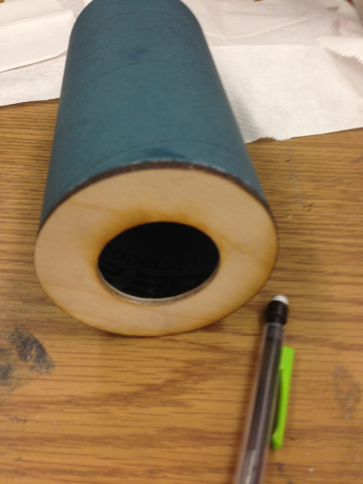
Here's the coupler, with a third 1/8" centering ring glued to the aft end. This only comes into play if the motor case is more than 15" long (a Cesaroni 6G or 6GXL), and provides a little bit of extra insurance that the motor stays straight.
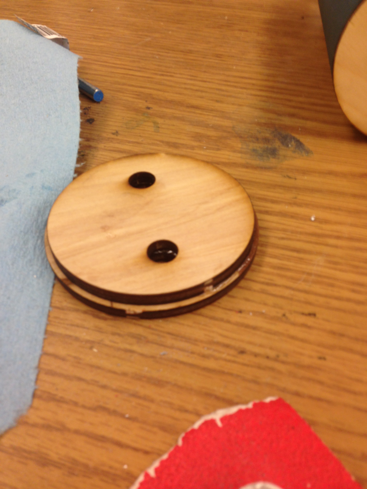
This bulkhead (consisting of two 1/4" pieces sandwiched together) goes in the other end of the coupler. It has holes for a short loop of kevlar that I can attach a quick link to. This is only attached AFTER the motor mount and coupler are in the rocket, and the 1/8" has been test-fitted with a motor case and sanded as necessary.
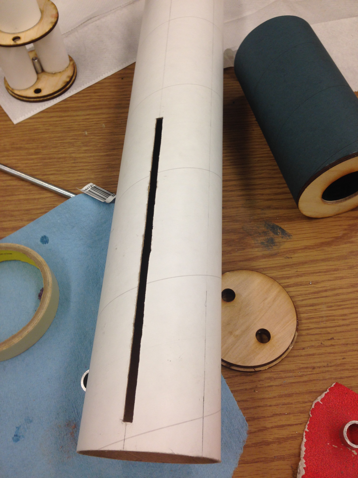
The lower airframe tube is slotted for fins.
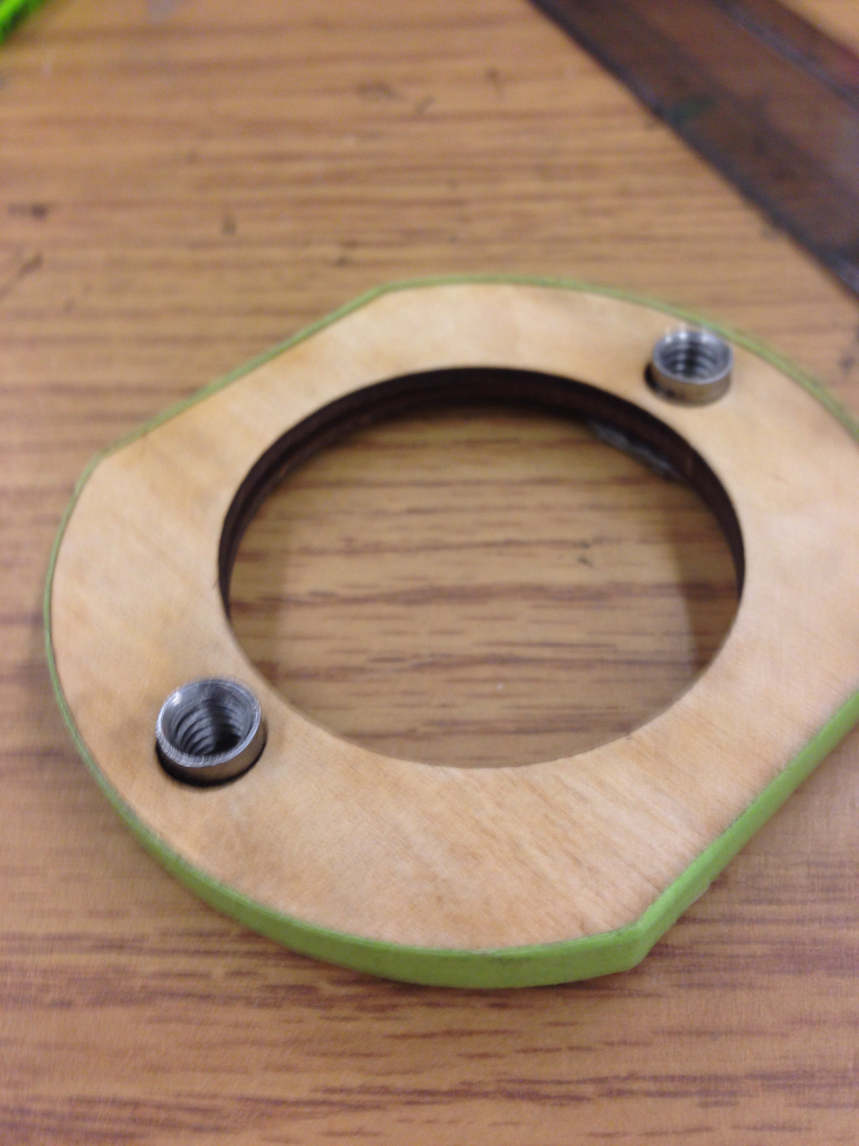
This is the avbay mounting ring, a 1/4" ring that gets epoxied into the piece of LOC coupler which serves as a nose cone shoulder and stays there. Two weld nuts epoxied in hold the mentioned 1/4-20 threaded rods that keep the avbay in place.
Here's what that looks like assembled. Note that the nose cone is a plastic one. The shoulder is chopped off and this piece of coupler is epoxied in.
The avbay, test-fit in the shoulder.
And, back at the booster section, the motor mount is epoxied in - but only the front ring. The rear CR was put in place to keep things aligned, but not attached to either the MMT or the airframe. It is removed once the epoxy sets. Off-camera, the coupler has been added as well.
Next, the fins are attached.
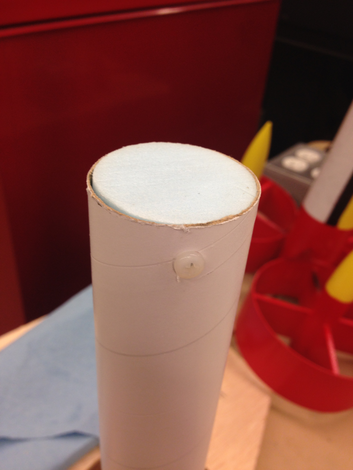
Here's the front end of the avbay. This is a foam plug that prevents whatever is in the tracker bay from coming loose and rattling around inside the nose cone. It's held in place by a pair of 6-32 nylon screws, but the threads don't actually do anything. In the background is another of my rockets, Development Hell. Named because it took FOREVER to finish; the fin assembly provides a clue as to why.
The rocket, like most cert builds, is a fairly standard 3FNC. It's 3" diameter and 54.5" tall (not counting about 3/8" of overhanging motor retainer), with a 38mm motor mount. The thing was first designed several years ago, but has gone through a few iterations before I actually ordered parts.
The design - not every component shown.
The airframe and motor mount are standard LOC cardboard tubing, but the coupler is blue tube, which should be a bit stiffer. The fins, bulkheads, and main centering rings are 1/4" plywood, and some minor components are 1/8".
Now, this rocket has a few unusual features. First, the avionics bay is built into the nose cone, and is a "sledless" design. There are three small bays: a pair of 29mm bays sized to accomodate a Raven 3 in a Featherweight 29mm Avbay kit, and a longer BT-60 sized bay in the front for any radio, GPS, or acoustic tracking devices that might be installed. It is dual-deploy; the apogee charge ejects the parachute and nose cone, and the main charge is located in an Archetype Rocketry Cable Cutter. In flight, the airframe never actually separates in the middle; the upper airframe is connected with Apogee's removable rivets. Technically it isn't zipper-proof, but the only part that could ever zipper is the upper airframe, which is very easy to replace.
Now, on to the build.
The first major part I put together is the avionics bay. As previously mentioned there are two altimeter bays (allowing for an upgrade to redundant altimeters), and a tracker/everything else bay. The tubes are just plain old thin-walled "Estes Grade" cardboard. The rings are 1/8" plywood, with the rear ring actually being two rings - one fitting the airframe, one fitting the nose cone shoulder - sandwiched together. The whole thing attaches to the nose cone with a pair of 1/4-20 threaded rods. A 6-32 machine screw and washer fit into a threaded standoff (bottom of the image), holding the altimeters in place.
Meanwhile, here's the motor mount. 9" of LOC 38mm MMT tube with 1/4" plywood centering rings. The rings are in contact with the ends of the fin tabs, providing a very strong assembly. The rear CR is unattached; it goes in later to allow for internal fillets on the fins. The three holes in it are for threaded 6-32 standoffs. As with the altimeter bays, screws and washers are used for motor retention.
Here's the coupler, with a third 1/8" centering ring glued to the aft end. This only comes into play if the motor case is more than 15" long (a Cesaroni 6G or 6GXL), and provides a little bit of extra insurance that the motor stays straight.
This bulkhead (consisting of two 1/4" pieces sandwiched together) goes in the other end of the coupler. It has holes for a short loop of kevlar that I can attach a quick link to. This is only attached AFTER the motor mount and coupler are in the rocket, and the 1/8" has been test-fitted with a motor case and sanded as necessary.
The lower airframe tube is slotted for fins.
This is the avbay mounting ring, a 1/4" ring that gets epoxied into the piece of LOC coupler which serves as a nose cone shoulder and stays there. Two weld nuts epoxied in hold the mentioned 1/4-20 threaded rods that keep the avbay in place.
Here's what that looks like assembled. Note that the nose cone is a plastic one. The shoulder is chopped off and this piece of coupler is epoxied in.
The avbay, test-fit in the shoulder.
And, back at the booster section, the motor mount is epoxied in - but only the front ring. The rear CR was put in place to keep things aligned, but not attached to either the MMT or the airframe. It is removed once the epoxy sets. Off-camera, the coupler has been added as well.
Next, the fins are attached.
Here's the front end of the avbay. This is a foam plug that prevents whatever is in the tracker bay from coming loose and rattling around inside the nose cone. It's held in place by a pair of 6-32 nylon screws, but the threads don't actually do anything. In the background is another of my rockets, Development Hell. Named because it took FOREVER to finish; the fin assembly provides a clue as to why.
Last edited: