jmattingly13
Well-Known Member
Quit hogging all the popcorn and let me have some. Sheez.
op:
There. That's better.
Plenty of popcorn to go around. Anybody else want some? Extra butter.


Quit hogging all the popcorn and let me have some. Sheez.
There. That's better.
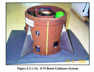
Feel free to post additional pics and descriptions of what you're doing. Looks like 6 canards?
Jim
Fast and slow are relative terms. In my world, the microsecond is normal speed......so a millisecond is slow......Unless I am missing something it seems to me that the pitch and yaw controls do need to be very fast in order to properly correct pitch or yaw when the rocket is rolling really fast. As a rocket rolls, what the system considered a pitch error will become a yaw error and then back to a pitch error again and so on. Consequently, if control fins are trying to pitch the rocket up then those control fins need to go back to a neutral position as the rocket rolls 90 degrees otherwise they will be yawing it right or left rather than pitching it up. As the rocket rolls another 90 degrees those control fins then need to swing in the opposite direction to pitch it up and so on. I have a mental image of the control fins swinging back and forth as the rocket rolls. The speed they need to move back and forth depends on the roll rate. (I think.)
Fast and slow are relative terms. In my world, the microsecond is normal speed......so a millisecond is slow......
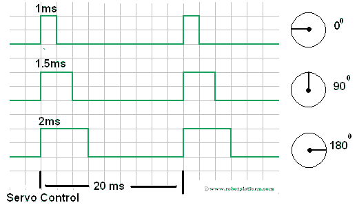
Let's looks at the RC class timing and the roll and pitch rates of a rocket and see what it takes to control them.
In a RC electronics timing cycle, the basic time unit is 0.002 seconds which is the period of the servo control loop. It means you can command changes in servo positions 500 times per seconds. Servo rate response times vary from 60 degrees motion in 0.05 seconds (fast) to 0.2 seconds (very slow) with an nominal 0.1 second time so the nominal angular velocity correction rate is 600 degrees per second per second.
For servos you should try to find servos that will run up to 7.4 volts and run a 2 cell lipo, this will typically get you more power in a given package. Most servos are rated at 4.8v-6.0v and may or may not burn out with 8v from a fully charged 2 cell. Also you should make sure you have metal gear servos with ball bearings. I'm the last couple of years they've come out with servos for robotics with aluminum cases, brushless motors, and metal gears. They're small powerful and built to take abuse.


Where do you plan on using the active stabilization, booster fins, fins on the upper stage like forward canards, some added forward canards, or in multiple areas. I was wondering what advantages/disadvantages each scenario would have.


The system looks really nice.
Two comments. The AA battery holder concerns me.
You could consider making two opposing servos set to be about 1/4 degree, or 1/32" , or whatever small measurement you can consistently make, to cause a slow roll for the unguided sustainer part of the flight. So, that would even out any unmeasureable error.
- George Gassaway
If you use LiPos, take note that two LiPos produce 7.4V, which will fry most servos, which usually are rated for 4.8-6.0 V (I've accidentally fried at least two). What I do for my R/C models with that problem (when not using servos rated for 8 volts) is simply use a 7805 voltage regulator, as i'm OK with running the servos at 5V. A 7806 might be better for the servo speed/torque
My concern is that the canards will be located well away from the CG. I would think that trying to induce or cancel roll would lead to coning?
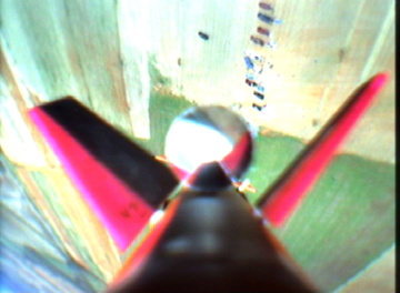
Although this only addresses the stabilization of roll, I thought it was pretty cool. The rollerons on the AIM-9 sidewinder are air driven gyroscope ailerons that are fairly simple in design ( simple meaning you are not me and know mathematics ) that were tested in an amature rocket here:
https://psas.pdx.edu/news/1999-09-13/
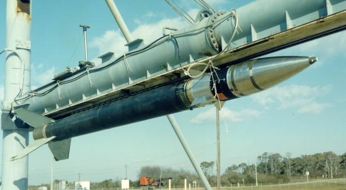
I don't believe that there is any connection. The ATACMS has its control fins at the back end and it flies roll stabilized with a spin up just prior to dispense. During that spin up the CG is somewhere in the payload section a long way from the fins.
You comment, though, is a good segway into the topic of my test rocket. I need to build something that I can use for testing, and I'm starting to think about what I want it to be able to do. Just as examples, would I want to be able to video the action of the canards? Do I want to be able to vary the CG/CP relationship? Is it possible to record the servo position or the PWM signal from the Guardian? I do plan to fly an EasyMega during the test flights which will provide acceleration and roll data. But, other ideas of what can or should be tested would be appreciated.

This looks AWESOME!
I wish I had more time for side projects, this would be a PERFECT application for 3D Printing. The servo mount could pretty easily be made all in one piece.

what's wrong with spin stabilization?
That makes things difficult with recovery components.
I have a rocket that has a high spin rate and I never noticed any problems with recovery.
Enter your email address to join: