


This kit looks SOOOO COOL! Must resist....
Don't resist the power of the dark X-15! :wink:
This kit looks SOOOO COOL! Must resist....
Hey Brent, did you build the 6" or 4"? If it is the 4", then it is likely that some changes occurred and maybe the tube wasn't cut down any longer. I did confirm with Bobby that I need to cut the bt down after gluing on the wraps. Note that this is a small/slow production run kit, so small changes may happen along the way. Bobby already noted that the newer batch of CRs will no longer be laser cut.
Saw H11 was in NY and got excited.....yea, 5 hours away.
Mine was the very first production run. I want to say about 5 years ago. Here is a launch video from 2011. Camera was mounted on tripod so it is just lift off.
First step is to inventory all the parts! Highly recommended since there are a LOT of small parts. Each of the three main assemblies (wing, tail fins, tail cone) uses CRs, bolts, nuts, washers and such.
Also it is recommended that you test fit everything. One of the CRs I got was cut off-center and so it wasn't quite working out (Bobby noted to me that my kit has laser cut wood; however future kits will use regular die-cut (?) wood CRs...which I would think would eliminate this type of off-register error
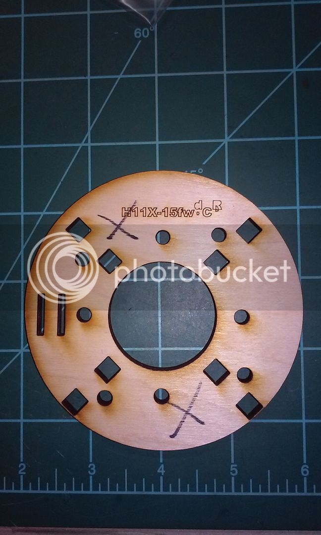
Bobby got me another CR lickety split, so customer support was very good! I guess it's helpful to be able to visit him. :wink:
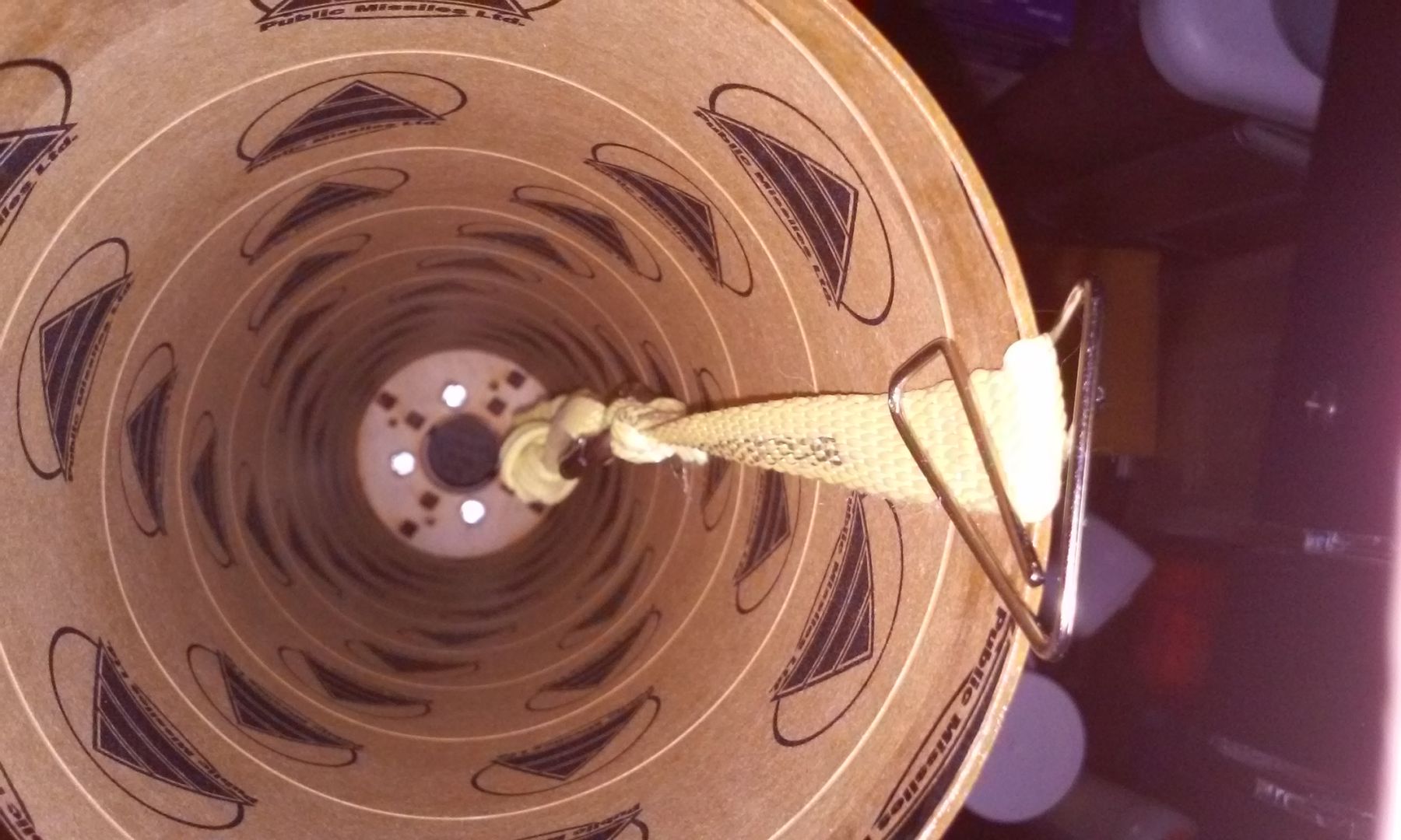
This is reason enough to buy the kit because it pretty much guarantees that the fins / wings will align perfectly! No more "eye balling" or using angle, not saying its bad to use those methods, but its nice to have it done for you
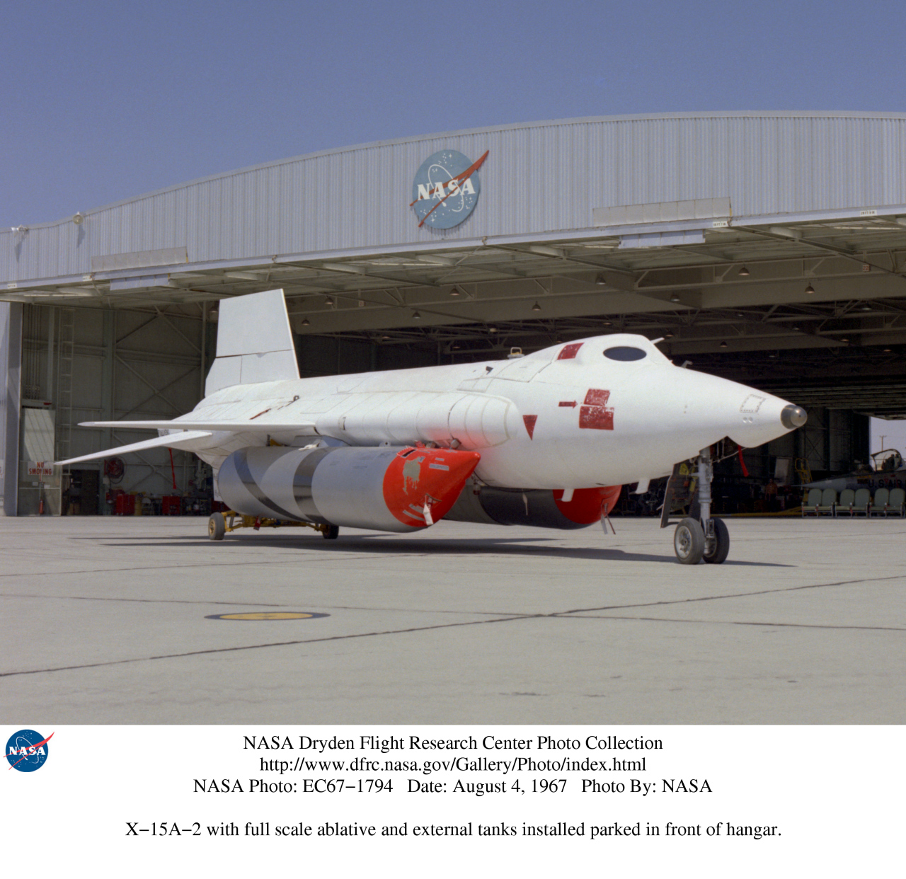
Stupid question but it looks like the tail coat and nose cone are pre painted? Does it come that way.
If I was to paint the kit I would go with a flat black and give it that military look. Not only that I can't paint worth a bird's dodo and flat black would be more forgiving. I would probably paint a silver tip on the nose cone.
This is reason enough to buy the kit because it pretty much guarantees that the fins / wings will align perfectly! No more "eye balling" or using angle, not saying its bad to use those methods, but its nice to have it done for you
Actually a good question. The wraps, nose and tail cone are molded in black material (you can see by the pieces I had cut off). Not quite sure what material it is...some sort of plastic. Bobby said I can use ABS glue or epoxy for bonding. Flat black sounds more practical; however I'm looking for a nice shiny black right now.

I have big hand maybe I should get the 6" kit? :lol::lol::lol:
So Ken what do you think of this design and assembly process?
What are your thoughts? Ken - you're doing a nice job on building this kit.
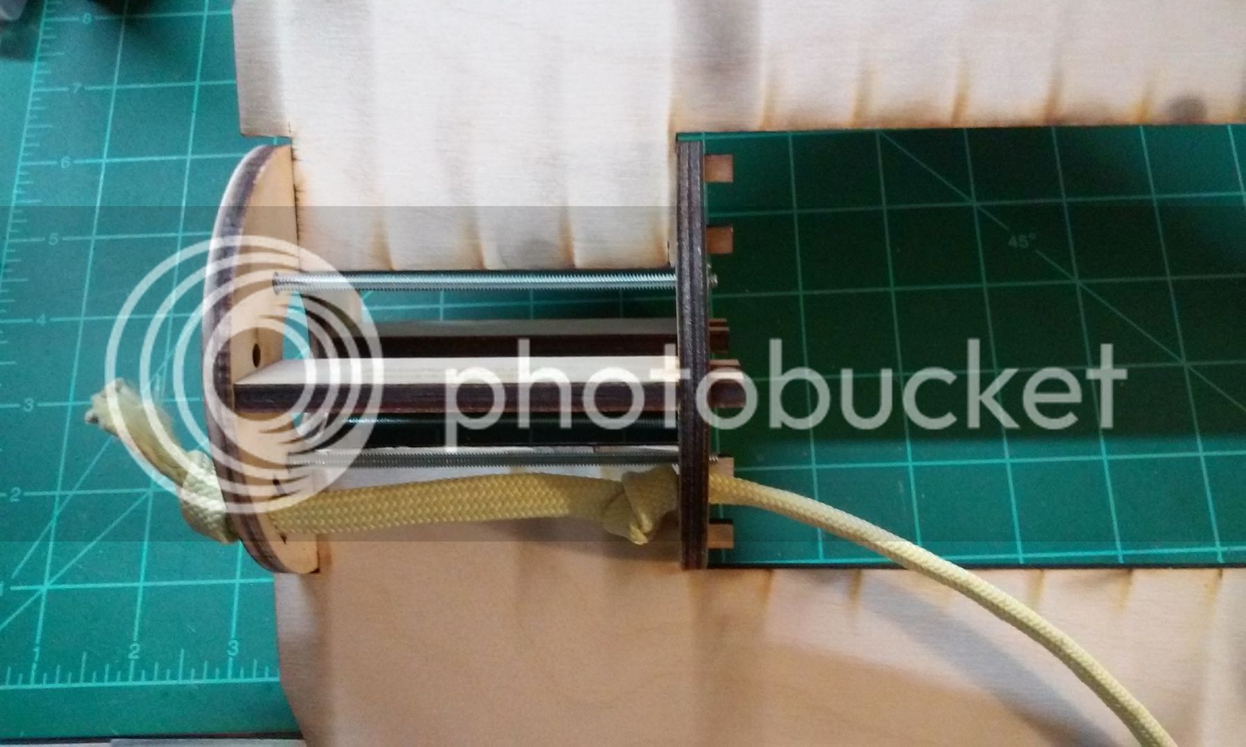
On the 6" version do you have to unassembled and assemble the motor mount assembly the same way....inside the airframe?
No, not at all. It follows a traditional build. No interlocking pieces. I had to do some adjustments to get the nosecone to fit/work the way I wanted and then some reinforcement of the tailcone, but that's about it.
That's cool....doesn't it fly on a 75?? I didn't look it up yet
Ken - you're doing a nice job on building this kit.
+1. This is a much harder build than the 6" version I have.
why worry about a deadline there are other launches. I never put a deadline on something. Take your time build it right and less chance for mistakes. Ken this is a great build and I'm enjoying watching it come together.
Enter your email address to join: