The key to getting a model like the Space Shuttle to fly straight, is to have the thrustline go THRU the Center of Gravity. And I do not mean the "see-saw" distance from nose to tail if you try to balance a built model horizontally. I mean the actual 3 dimensional CG. In the image below, the actual crosshair dead center of the CG symbol, not the simple distance from the nose.
For a shuttle, if you put the engine mount in the dead center of the ET, of course the mass (and drag) o the orbiter would make it pitch badly onto its back. If you had the engine mount literally glued to the inside of the ET, on the orbiter side, the thrustline would be too far on the orbiter side of the CG, and pitch nose down at launch.
The Estes kit, of course, had the centering rings set so the engine mount would offset towards the orbiter, but not all the way on the inside of the ET. I presume they made many prototypes to discover where the 3 dimensional CG would be for a "typical" model, and then chose how far to have the engine mount towards the orbiter. But some people over-built the shuttle, primering and filling and painting it to death, almost literally. Making it too heavy on one side, or the other. Also, IIRC, the orbiter had the elevons rigged to be held flat for boost and spring up for glide. I figure some people screwed that up and had the elevons up, which was not good for boost unless the CG was on the wrong side of the ET and would by pitching down at liftoff.
Anyway.... for my later shuttle models, some at 1/72 scale, I built the whole model firs,t except for the engine mount, and delaying the install of the Et aft dome. Then I used a set-up to suspend it vertically for balance, so I was able to find out EXACTLY where the thrustline needed to be to have the thrustline thru the CG, With that info, I made the centering rings and completed the rest of the assembly.
Fortunately, for a shuttle configuration, the drag based on frontal area causes a sort of "center of drag" that was in the ballpark of the thrustline. The way I discovered that involved a supercomputer CFD program taking 4.3 days to calculate.
No. Actually, I attached a printout of the top view of the shuttle, onto a sheet of plastic, and cut out that sheet of plastic according to the outline. Then I balanced it in several directions to find out the intersection which was the Center of Frontal Area. Which I chose to approximate the Center of Drag, even though there is less drag from the wings than from the rest of the shuttle stack....I figured close enough (I could have fine-tuned that if I felt it necessary, by literally chopping off some of the wingspan from the cutout to approximate what I felt was the less drag of the wings compared to the rest of the stack). But I had no way to adjust the Center of Drag in any case, only the Thrustline based on the 3D Center of Gravity. Again, the cut-out showed it was "close enough".
Yes, that method was like the old-school classic paper cutout method to find the worst-case Center of Pressure. Was so easy and relatively quick to do, than even try to comprehend how to do anything with calculations (which I would not have trusted anyway).
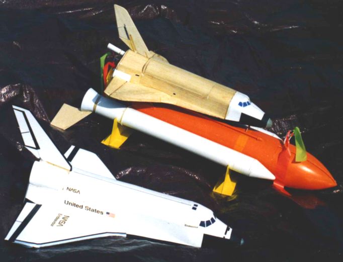
Below is a photo of my 1998 1/72 shuttle stack boilerplate, with 1/60 orbiter. Note the fin configuration, which was far less than used for the shuttle kit by Estes (one fin per SRB, at 45 degrees down relative to the wings). This meant that I had to be so much more careful to get the thrustline exactly right, and had to consider the Center of Frontal Area (drag). The fins on the Estes kit had a much larger margin for error, but enough models were built with enough error to not fly well.
BTW - one way to address rockets that may pitch due to asymmetry, is to cause them to roll. For a clustered model, skew (twist) the engine mounts. For single engine, roll tabs or slightly skewed fins.