Extreme Wildman - Pink Fractals Edition

The Rocketry Forum

Help Support The Rocketry Forum:

This site may earn a commission from merchant affiliate links, including eBay, Amazon, and others.

smapdiage9

Well-Known Member
Joined
Mar 14, 2009
Messages
442
Reaction score
3
I purchased the Extreme Wildman 4" kit a few months ago for a couple of reasons. First, it was the next kit in the Wildman line that I didn't own yet, and second because I wanted something a bit nicer and roomier for L2 flights than my GLR Vertical Assault. The VA has been my workhorse for several years, and I certed both L1 and L2 with it, so it's time to burn propellant with a rocket that's a little bit bigger and slicker. The long term goals for this include working my way toward an ultimate wildman build (basically the same rocket 50% bigger) which I've wanted to do forever, and finally having a payload big enough to carry a decent camera.

This is also the first rocket project I've undertaken that really has to be flown on at least a J; I guess technically an I800 will get it off the rail at a decent speed, but apogee at 600 feet seems kind of anticlimactic. By the stock rkt file a K535 will get it to 4.4k and an L935 to under 10k. I'm not much of a sport rocket guy as high performance stuff has always caught my attention better, but the realities of my local waiver mean I might as well have some loud fun flights below 10k so here we go.

The kit has been built better by other people so I won't document that exactly. What I will say is that this was the first HPR build where I broke stuff down into work types instead of build segments, meaning that I used a silver sharpie to replicate the markings done in the kit instructions for measurements on each aspect of the airframe. Then I did all of the drilling operations which could be accomplished up front, and following that I completed all of the sanding that could be done up front. These two decisions made the actual gluing and assembly a total breeze.

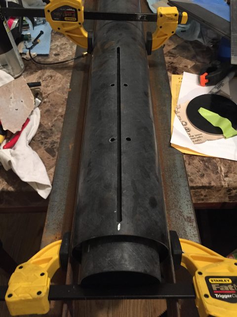
Fin alignment was the first major effort. I used a level and a square to clamp my body tube between two pieces of angle iron with the fin slot exactly at the top, then taped the level to the fin to make it sit upright.

4yjkA6tl.jpg


Xx2K0YIl.jpg


All three fins tacked in place with rocketpoxy, they are set but not fully cured:

WZaRwizl.jpg


The directions were written for a slightly thinner base epoxy (west) with translucent green FG tubing that is no longer supplied. Using rocket poxy, chopped carbon fiber, and the black tubing the injections went well but I had no way to verify how far along the fin root they would cover. Additionally, I found that tilting the airframe did little to flow the epoxy as even when thinned with a lot of black pigment the viscosity with the fibers in it was quite high. To give myself peace of mind I did initial injections with 10ml per side in the stock hole locations (1/3 and 2/3 down the root) and allowed them to set up. Then, I drilled inspection holes nearer the two ends of the fin root and found that it really hadn't flown that far, so I made a second injection with much thinner aeropoxy near the forward and aft end of each fin through those inspection holes to assist with reaching the centering rings and rest of the root. Ultimately each fin received its 25ml of rocketpoxy distributed across four holes per side instead of two with the fin-cr joints getting some additional aeropoxy for good measure (mainly because I was out of rocketpoxy for a couple weeks).

When doing external fillets I also found that the stock 1/4" injection hole locations were not fully covered by the fillet radius I wanted to use which was kind of annoying. On the next one I'll probably intentionally size my injection holes to the size of my syringes (smaller than 1/4) and make sure that my holes are a little closer to the fin.

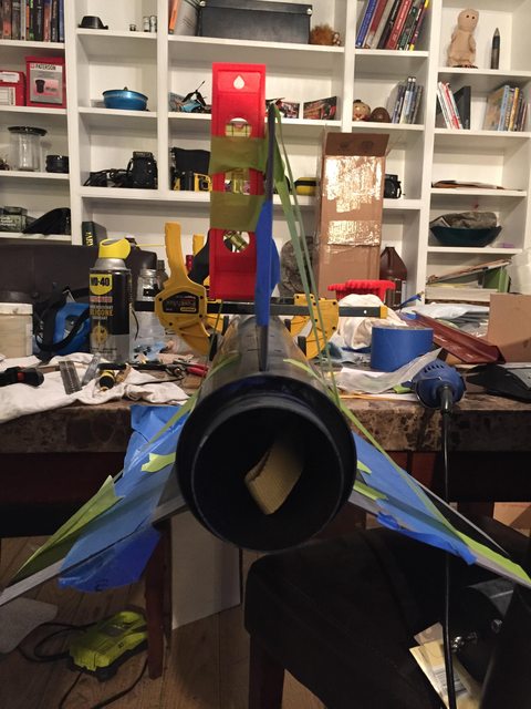
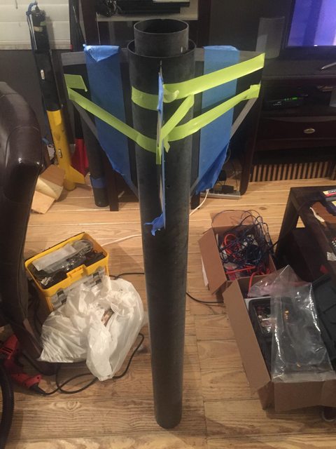
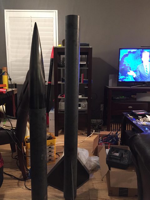
My realization that this is going to be a big damn rocket occurs as I realize I can't actually assemble it indoors with my low ceilings:

vs6tbRBl.jpg


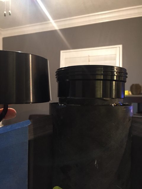
I used the Aeropack instructions to determine my motor tube overhang for the retainer. Hopefully it works out because I still haven't tested it with any 75mm hardware.

Z5nOcVKl.jpg


I am the world's worst builder in terms of finishing aesthetics, and it probably doesn't help that I really don't care about good paint jobs anymore. This is the biggest rocket I've ever built, and the tremendous quantity of epoxy required for fillets meant bubbles and sunken portions were even worse than normal. Yes I spread the rocketpoxy out thin to get some bubbles out, but it just never seems to settle perfectly for me on big ass fins like this. My reently purchased harbor freight oscillating sander was used judiciously to even things out. Again, I hate painting. Because of that I decided to commission a wrap from StickerShock23. Knowing that the wrap would cover everything but the tip of the nosecone, the fins, and the tailcone, I was only required to paint the fins on this rocket. Black gloss got rid of the gray streaks from sanding and beveling, but also made the fillets look even worse. No worry, those will be covered up soon.

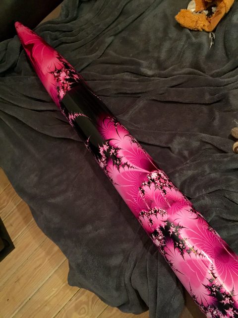
I wanted something a bit outrageous and trippy for this build, so I chose a pink fractal pattern for the entire airframe. I started the wrap on the nosecone, which would turn out surprisingly to be the easiest part. The large tubes were challenging, and if I do it again I'm definitely gonna use saw horses to set up a little rotisserie instead of just doing it on a table.

Nosecone and payload in progress:

EJb5WlYl.jpg


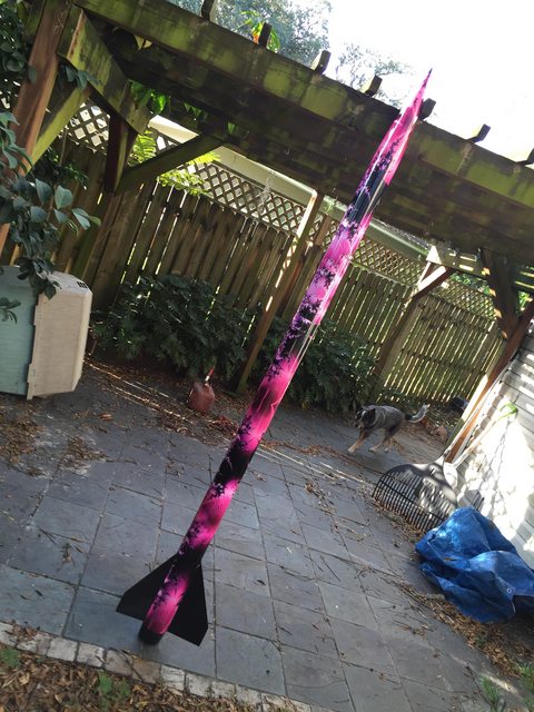
The whole rocket wrapped:

IzmUVBXl.jpg


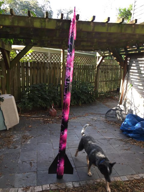
This thing exactly fits my aesthetic demands: it's lazily constructed up close, but from 10 feet away looks amazing. The seams, bubbles, and other little errors totally disappear once you step back and I'm extremely happy with the way it turned out.

lttGCXvl.jpg


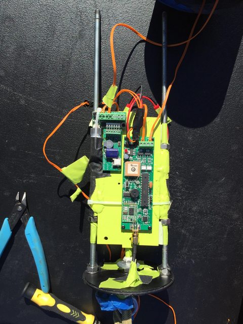
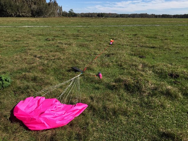
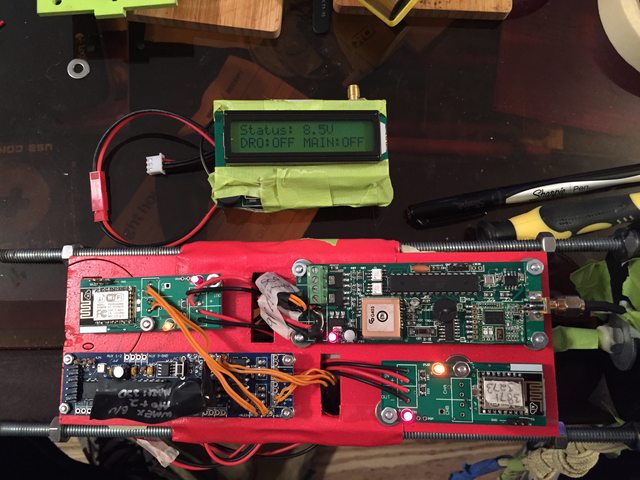
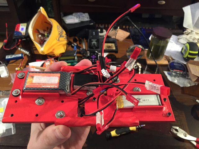
This week my goal is to figure out the avionics bay and do some ground tests. I've always been a friction fit guy and never used shear pins, which this one definitely uses, so it'll be interesting to see how that goes. I've got an 84" pink parachute as the main to match the theme. I also drilled a mounting hole in the booster tube to positively fix my keychain camera, which I've traditionally just held on with gaffer tape on other L2 flights.
 
Last edited:
Beautiful rocket. Can you please explain how the wrap works on the curvature of the nosecone? And the abrupt angles around the fins? These discontinuities have always made me shy away from using the wraps, but obviously you made it work out perfectly.
 
No problem, I had the same questions but emails and website videos from StickerShock23 cleared it all up nicely. For the nosecone, you cut a rectangular portion of the wrap into three shapes that are vaguely nosecone profiled. Apply one, then use a piece of masking tape from the tip to the base as a straight edge along each side to exacto trim the excess, and repeat twice with small overlaps. The seam all but disappears from a few feet away. For the fins, I cut off three sections of the main booster tube wrap that were sized to fit in between the sets of fins. At the edges they wrapped in odd shapes around the fillets, so I made small slices with my knife to ensure it lay nice and flat. There was a small amount of overlap with the main wrap around the booster tube, maybe 1/8-1/4 which again disappears when you step back. I was worried about the pattern not lining up perfectly, but it's busy enough that you really can't tell.

These videos explain it well, and he marked all the cuts I needed to make on the back of the material before shipping it. Made it very easy:

https://www.stickershock23.com/How_To_install_Decals.html

Thanks!
 
Awesome! Any L3 plans?

Even if not, a short case in 75mm would probably serve you well. Those 54mm6XL motors are crazy expensive for what you get.
 
I've acquired a couple 75mm snap ring cases and the AMW/Pro75 adapter so I can fly 2-3G CTI 75mm stuff pretty easily.

I do intend to knock out my L3 eventually, but that will have to wait until 2016. I briefly considered it with this, but even a teeny tiny M won't stay under my local 12k waiver in a 4" rocket. Because of WM's Black Saturday there's now a set of 6" red fiberglass tubes sitting in the corner of my living room waiting for that. It won't hurt to get more L2 flights under my belt with this rocket that is pretty big and pretty heavy compared to my other projects in the mean time. :)

I see. Good plan and nice build. Enjoy flying it! Mine was a blast. L910 cstar here, photo courtesy of rcdude.

XYIRmaM.png
 
Thanks! I like your paint, the blue and black contrast is cool. Might have to steal that for another build!
 
Discovered a fun surprise today while researching other people's builds: the nosecone coupler is a separate piece and not glued in from the factory. I didn't see that mentioned in the instructions, and only tried pulling it out because I read in someone else's build that their NC had "not glued in" written on it. Mine did not, and appeared to be a rock solid single part this whole time, but with a little twist it popped right out. Glad I learned this lesson now and not this weekend at the launch!
 
Discovered a fun surprise today while researching other people's builds: the nosecone coupler is a separate piece and not glued in from the factory. I didn't see that mentioned in the instructions, and only tried pulling it out because I read in someone else's build that their NC had "not glued in" written on it. Mine did not, and appeared to be a rock solid single part this whole time, but with a little twist it popped right out. Glad I learned this lesson now and not this weekend at the launch!

Hah, did you find mine? While dry fitting I got a coupler stuck so hard that nothing could get it out. Tim even chimed in, but despite all the advice it would not budge. I wound up giving in and stuffing some rivets through to make sure it could not come out at a bad time.
 
I may have seen yours, I've been googling my ass off for other people's builds as usual. Copied someone else's deployment charge amounts (3.0 drogue 3.4 main) and completed my ground testing today which worked out fine.

2-56 nylon shear screws snapped off cleanly and the full burrito (84" top flight) left the tube energetically, but my rubber banded z-folds of tubular nylon did not fully unravel so that's probably just the right amount on the ground. I used a 75mm/3500 snap ring case with a taped over forward end to simulate a motor, and 3.0 grams more than energetically separated the two sections.

Ordinarily I conduct ground test by fishing the charge leads out of the body tube, connecting them to 40 or 50 feet of old speaker wire, and slapping the ends against a 9v battery. This was the first time I used the built in charge test function of the Eggtimer TRS / LCD controller. This was cool except I didn't realize that the altimeter has to be rebooted after each firing, and the way I assembled the ebay means I had to remove the 3 screws holding it to the payload bay, remove the upper bulk plate, slide the sled out, and redo the battery connection. Once I had it back together, I accidentally re-entered the Drogue Test screen instead of the Main Test screen, which meant I had to redo all that stuff AGAIN which was irritating. I don't have any switches set up in this system right now because the TRS has a separate battery for optoisolated deployment charges so I can just twist and tape that battery power to arm everything at the pad. Definitely gonna look for a couple switches on the next build.
 
Pics to document the test rigging:

bQsCYxCl.jpg


L1Eo0CUl.jpg


zl60FdNl.jpg


The standard harness is used for the fincan: 1" kevlar webbing (4000lb breaking strength) epoxied to the MMT with an overhand loop at the end. Note that anywhere the recovery harness crosses a tube transition point it's wrapped in several layers of 3" wide blue painters tape and the hard edges have been sanded down.

The drogue harness is the longest and consists of 30' of 3/8" tubular kevlar (3600lb breaking strength). At each end the connections are made by tying figure eight follow through (https://www.animatedknots.com/fig8follow/) knots through the MMT harness loop or a 1/4" welded stainless eyebolt.

Things get interesting in designing the harness where hardware comes into play: the stock eyebolts have a ~400lb working load limit. This defines a continuous safe load, not a failure point like the breaking strength of the cloth materials, but it's also assuming a straight pull. At a 45 degree angle the strength limit can be reduced to 1/4 of its stated capacity. The recovery sequence of the rocket represents a somewhat uncontrolled pull, potentially sharp application of force for a very short time so who knows what actual load it will experience. Since this hardware has flown in similar rockets enough time to be provided stock, we'll just assume it works if recovery occurs within a reasonable envelope.

I am always worried about twisting forces during descent where fasteners are used. For the two avbay eye bolts, a nut and washer on either side of the bulkhead allow the bolt to spin without unscrewing. A dab of epoxy will hold the nut to the threads but not the washer. Cotter pins or safety wire would be a better solution but I don't really want to drill holes in threads.

This kit came with aluminum avionics bay bulkheads which transfer the load from the eyebolt to the allthread. I have no idea of the alloy, strength ratings after machining, or how the drilling of holes through it has affected its ability to carry loads.

The steel all thread carries the recovery weight through the avionics bay. I don't know the grade provided, but even grade 2 ratings for steel 1/4-20 threads are like 1750lbs. I, like all rocket people, have not done any math or used a torque wrench to figure out how much loading I'm putting on the thread during assembly, so much like the eyebolt case it's basically inshallah.

The main-side harness is using the stock supplied ~24 feet of 9/16" (I think) tubular nylon rated at about 2300lbs breaking strength. Again I use figure eight follow through knots to secure it on one side to the avionics bay eyebolt and on the other side to the nosecone harness. A few feet south of the nosecone I tied an overhand loop into the harness where a way overkill D ring is installed (50 KN) because it looked smaller on amazon when I bought it. D ring houses a 1500lb swivel for the main chute and the 16" square chute protector so that it won't ride the lines up and stifle the parachute. Parachute is looped through itself to attach to the swivel, then an overhand knot tied just below the swivel to prevent unraveling.

Parachute is a Top Flight 84" rated to carry an 18-24lb load down at 17-22fps. Normally I put the parachute at the end of the harness and the nosecone in the middle but I decided to go traditional on this one to ease packing.

I removed the stock bolt holding my nosecone tip in and replaced it with an extra 1/4-20 welded eyebolt. Some of that nylon is again tied to form a harness, and a 500lb swivel is used between the cone and the harness to prevent any unscrewing.

So with a target burnout weight of about 20lbs and a desire to withstand a 50G deceleration under a faster than ideal deployment the entire harness needs to have no link weaker than 1000lbs. As a means to further reduce deployment shock loads I z-fold all the long lengths of harness into 5-10 foot sections that are held together by a rubber band. The knots were chosen because they are climbing knots that affect the strength of the rope less than others might, but we'll be safe and still say each piece of nylon/kevlar is only at half of its rated breaking strength after the knots are introduced. The small swivel for the nosecone will only carry the cone's weight so 500lbs should be fine. For all the other metal parts in the harness, we'll just pretend that someone did some engineering and they're good to go. Same deal for the epoxy adhesion of kevlar to MMT.

Come to think of it, I don't think I've ever seen a build thread (even L3 projects) where someone actually documented all the forces at play for hardware in an engineering way. I'm sure someone has; I'm not smart enough to, but if I ever stumble upon that work I will include it in my decisionmaking for the next rocket.

Right now the airframe and recovery gear (so everything but the motor and my electronics sled) are weighing in at ~13.1 lbs which is about 3lbs less than I was expecting based on other people's builds. I'm guessing main parachute choice has a lot to do with it, also I did build it without the NC bulkhead, and my sled with two altimeters, three lipos, and four charges should add a fair bit so I suppose it's not too far off.
 
Last edited:
Successful flight to 4500' today on a CTI K630 blue. Everything worked as intended, Eggtimer TRS was primary with a Raven as backup. Conditions were very windy but the tracking smoke on this motor was really good and I saw it all the way up. The prep work with shear pins, four charges, screws to retain the payload tube to the avbay, and a new 75-54 aeropack adapter was all a little arduous but I chugged through it fine.

Let's all pretend that my sled isn't a hodge podge of leftover laser cut wood, way too much epoxy, unused PML launch lugs, and popsicle sticks cut up to make battery boxes on the other side and just admire how well the paint matches my tape:

F2MoxSEl.jpg


fPf2bKLl.jpg


IHYKlvSl.jpg


zLGrrwkl.jpg


I'll have to go for an L next time!

X90IXrXl.jpg
 
[video=youtube;7Xfz4brQH0o]https://www.youtube.com/watch?v=7Xfz4brQH0o[/video]

From the rocket. I thought I was gonna hit that cow on the way down.

Some data from the flight. This is the biggest motor I've ever flown but it was a pretty low performance flight; 10Gs off the pad, 375mph, which is hilariously less violent than the I205 on my Wild Child.


Lateral Gs are heavy: Momentary instances of >30G axial loading after apogee as it's rotating down under drogue, including one weird peg to almost -50G.

Axial Gs at apogee show about +25G at peak which I'm assuming is the acceleration force of the ejection charge pushing the avbay followed by a low peak at -10G which should be the drag of the drogue.

Main deployment showed a -47G peak which should be the ejection charge (avbay is upside down hanging under the drogue) and the chute opening showing +16G or so.

I am guessing that the forces acting on the altimeter when the charges blow are not necessarily producing loads that have to be carried by the recovery harness, but the rest of them ought to be considered.
 
Last edited:
Is that chart coming from Eggtimer or Raven data?

Nice flight. You could hit it with a K740 or even K2045 if you want some middle ground with that same case. In 6XL I think the popular ones are L935 and L1030, but any of them should be a blast!
 
I have a K535 on the way for some low flying if the next launch is as windy as this one, but I definitely want to get it up on some 2-3G 75mm motors.

That chart is from the Raven file. The TRS doesn't have any accelerometers unfortunately, and since the LCD receiver showed nearly the same apogee altitude as the Raven reported I didn't bother downloading it. The Raven was actually doing backup duty for deployment charges, so its commands are a little delayed from actual apogee and main deployment.
 
Last edited:
Hopefully gonna get this one up on an L910 this weekend.

Because I needed the raven for another project and had a bunch of Eggtimer parts laying around I made a 2nd version of the sled to carry the TRS, an eggtimer, and two WiFi switches. On the last setup I could activate the raven with a magnet, but keeping the TRS' deployment battery disconnected without a physical switch meant I had to twist and tape the deployment power. I prefer things to be snazzy and needlessly complicated, so now my eggtimer will have its entire power and arming setup done through one wifi switch with charge continuity reported to my phone, and the TRS will have the second wifi switch activate its deployment battery once on the pad with charge continuity reported to the LCD receiver.

This project also helps me get practice making a dual redundant electronics setup which will swap easily into my ultimate wildman project, can remotely disconnect power to both pyro setups without an external switch; if that project should require a need to "break physical contact" then I can easily do another twist and tape or switch or whatever.

So with a little bit of measuring and laser cutting some scrap pieces I played around until I found a physical arrangement that worked:

QCwlqlDl.jpg


There are a lot of damn connectors on this thing:

nmUV2Ddl.jpg


1000mah 2s lipo -> TRS GPS power (draws 200-250mah)
250mah 2s lipo -> wifi switch 1 -> TRS Deployment Power (draws 80-85mah)
500mah 1s lipo -> wifi switch 2 -> Eggtimer Logic and Deployment Power (draws 80-85mah plus 5-10mah)

So the power draw of the wifi switches means fairly sizeable capacity requirements for a couple of the batteries. I have ignored doing any research into the current sourcing ability of these batteries during ematch firing compared to the ability of the channels to handle that since it seems to be working for everyone else and it's worked great for me on many flights.
 
Nice rocket! What descent rate are you getting on your main? I'm using a SkyAngle 60" on my Extreme Wildman but it comes in pretty fast, like 23 fps or so. Your main deploy altitude seems pretty low (300 feet?) but you were on the main for 30 seconds about, which is a really low descent rate unless I'm reading the graphs wrong.
 
Come to think of it, I don't think I've ever seen a build thread (even L3 projects) where someone actually documented all the forces at play for hardware in an engineering way.
I've never been able to come up with a good way to estimate the jerk force at deployment without knowing something about the elasticity of the harness materials. I guess you could determine that by test.
 
When reviewing other people's builds I found that some people used 60" chutes with success, but by the recommended descent rate chart from Top Flight or the higher end of the built weights with large motor casings I played it to the conservative side. The main on that flight was blown at 500', fell to about 350' before inflating, and fell at 12-15fps which was a bit more gentle than I wanted. I set the main low due to winds, but it appeared to be catching some updrafts during the descent which definitely reduced the speed.
 
The most common 60in chute used/recommended are the Recon or SkyAngle....not a flat sheet 60in.
For that the 84 Topflight is perfect. You are using the recommended recovery gear & should be experiencing, nice gentle recovery.

You have a nice build and should have a lot of trouble free...fun flying with your rocket....I like the PINK. Very different.

PS... yeah these modern bays, full of latest electronics are becoming a pain in the butt. I kinda miss just flying a single altimeter and calling it a day.LOL
 
Last edited:
Oh duh, I pretty much use flat chutes exclusively so I forgot about different shapes. Thanks!
 
PS... yeah these modern bays, full of latest electronics are becoming a pain in the butt. I kinda miss just flying a single altimeter and calling it a day.LOL

+10 on that! I still try to just fly the single altimeter. On most of my L1 & smaller L2 birds, a new Duracell 9V goes in at the start of the season and as long as the voltage is at 8.8 or higher, it doesn't get opened again till next season. The ones with only a few flights that are at 9.1 or more at the end of the season might get 2 years on the same battery. At least I know the battery is flight tested and proven to work. I think the risk of battery failure is higher with a new battery then a proven used battery on the second or later flights.

For all of you that enjoy building and playing with all those electronics and batteries, just ignore me!
 
Oh it's certainly possible to achieve the same thing with a waaaay simpler setup if that's what you're looking for. I think the effort is totally worth it for the data, and love the fact that I soldered all this crap together myself, just to add another layer of emotional investment into the project. :wink:
 
Back
Top