98mm Min Dia L3 Build

The Rocketry Forum

Help Support The Rocketry Forum:

This site may earn a commission from merchant affiliate links, including eBay, Amazon, and others.
In the testing that I did, which included the double-sided "T" approach and the single-ended tube approach, I did not seal the charges at all, other than to use a little Estes wadding to hold the BP in place. In all cases, a couple of dozen times anyway, the charge fired very energetically with 100% of the powder burned. This only happens with the longer tube. I do seal the charges now, but other than possibly improving the effectiveness of the ematch, there is no improvement in the performance because the charges are already burning 100% of the powder.

In the longer tube, the "sealing" function if provided by the longer tube itself. As the charge begins to fire, I suspect that the BP tries to scatter by moving up the tube. However, this scattering is contained within the tube instead of being released into the drogue cavity. There is enough pressure produced by this initial burning to build up some pressure - like sealing might otherwise do - so that the charge completely fires. It is very energetic, very simple, and very reproducible. I typically use a little less BP than I might use with a conventional charge at lower altitude, because 100% of it is going to burn.

If the tube is limited in length to that of the charge itself, and even if it's taped shut, the BP does not entirely burn (in my tests, about 50% burns in this configuration). Here, as soon as the seal ruptures, the BP scatters and stops burning. In the longer tube, the BP can't escape fast enough, and it burns before it can get out of the tube.

As I always say when discussing this method, deployment is very energetic. Anyone doing it should do ground testing first, and conduct that testing carefully (because another name for a one-sided charge is "bullet").

Jim

Don't Debate This had reallly really long tubes: 15" or so? The entire length of the parachute bay, if I recall correctly. That has the advantage of also bypassing the hot gases past the parachutes.
 
In the testing that I did, which included the double-sided "T" approach and the single-ended tube approach, I did not seal the charges at all, other than to use a little Estes wadding to hold the BP in place. In all cases, a couple of dozen times anyway, the charge fired very energetically with 100% of the powder burned. This only happens with the longer tube. I do seal the charges now, but other than possibly improving the effectiveness of the ematch, there is no improvement in the performance because the charges are already burning 100% of the powder.

In the longer tube, the "sealing" function if provided by the longer tube itself. As the charge begins to fire, I suspect that the BP tries to scatter by moving up the tube. However, this scattering is contained within the tube instead of being released into the drogue cavity. There is enough pressure produced by this initial burning to build up some pressure - like sealing might otherwise do - so that the charge completely fires. It is very energetic, very simple, and very reproducible. I typically use a little less BP than I might use with a conventional charge at lower altitude, because 100% of it is going to burn.

If the tube is limited in length to that of the charge itself, and even if it's taped shut, the BP does not entirely burn (in my tests, about 50% burns in this configuration). Here, as soon as the seal ruptures, the BP scatters and stops burning. In the longer tube, the BP can't escape fast enough, and it burns before it can get out of the tube.

As I always say when discussing this method, deployment is very energetic. Anyone doing it should do ground testing first, and conduct that testing carefully (because another name for a one-sided charge is "bullet").

Jim

Jim I do see how this could work. I guess from my perspective it is what I do with all my flights (well 95% of my flights) no matter the projected altitude. I use copper tubing that is 2X to 3X (or more) the length of BP I need. Stuff it with wadding and seal with high adhesive metal tape. It goes off like a shot gun. Never have used plastic bags, surgical tubing or latex glove fingers. Sometimes I will use centrifuge tubes when space is limited, but then I wrap them fully with the metal tape to get the same effect.

You certainly have more experience with high altitude flights than I have, so I can't argue with your methods. I am trying more and more high performance minimum diameter flights though (one planned for 50K which I may have ready for Airfest) and I am typically one that will research best practices like crazy, thus my plan is to go the highly contained, sealed route per NASA and DoD studies. I'll let you know how it works out.

Lots of ways to do it. Sounds like your normal way would be just fine at high altitude, but you get to do what you want. By the way, your AirFest flight is only 49K ... right?

Jim
 
I have been busy lately, but still have some updates. I have gotten the motor casing and the motor in; seeing as we all love pictures... pictures will come. I have all the electronics that are needed and I am working on the payload bays. In about a week or two from now I hope to start machining some pieces that I need for this flight. After that I hope to have most of the vehicle complete (in the sense of measuring mass) minus the fins. Once that point is reached I will finalize/start making the fins and then attaching them on. I am saving the fins for last because I think this makes the most sense for a flight profile such as this. This allows me to better design the fins for this flight with actual measured mass.

I am currently however dedicating most of my free time to the thought process of the fin attachment method and all that is involved in that. So until I finish with my epoxy decisions/testing I will not do anything further other than what has been mentioned above. I am planning on having some epoxy samples ready to go off to the lab by the end of this week or the start of next week.

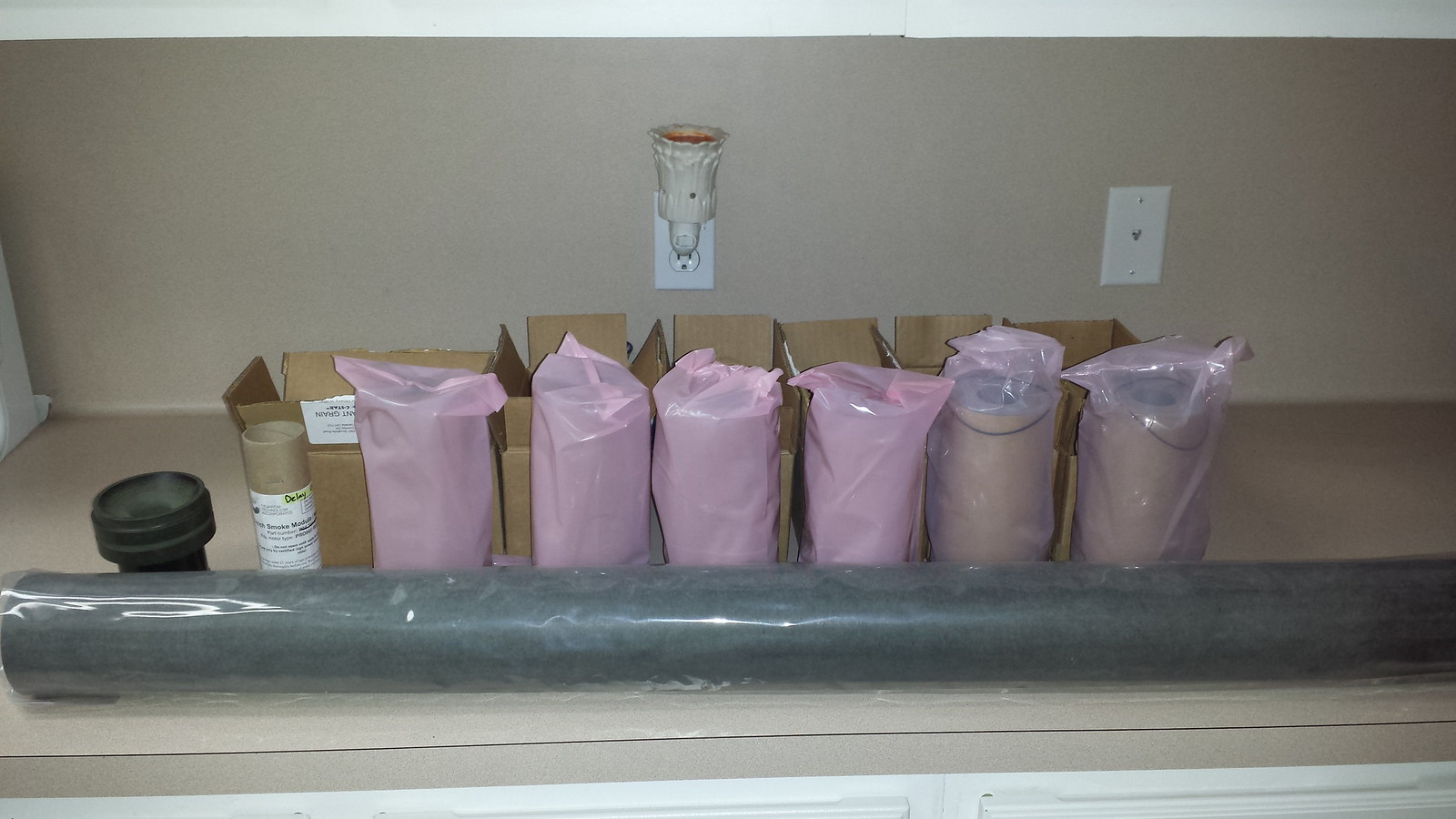
And now here are the promised photographs.

14040032298_8d4dee078a_h.jpg

In case some people have not guessed which motor I will be using yet… that is a CTI N5800.

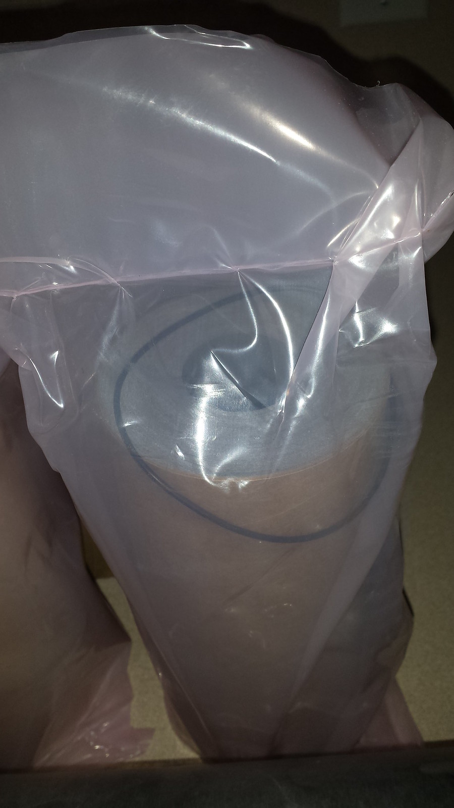
14040111147_28a8cb968f_h.jpg

Up close of the grain. Sorry I do not plan on breaking the seals until closer to the launch date.

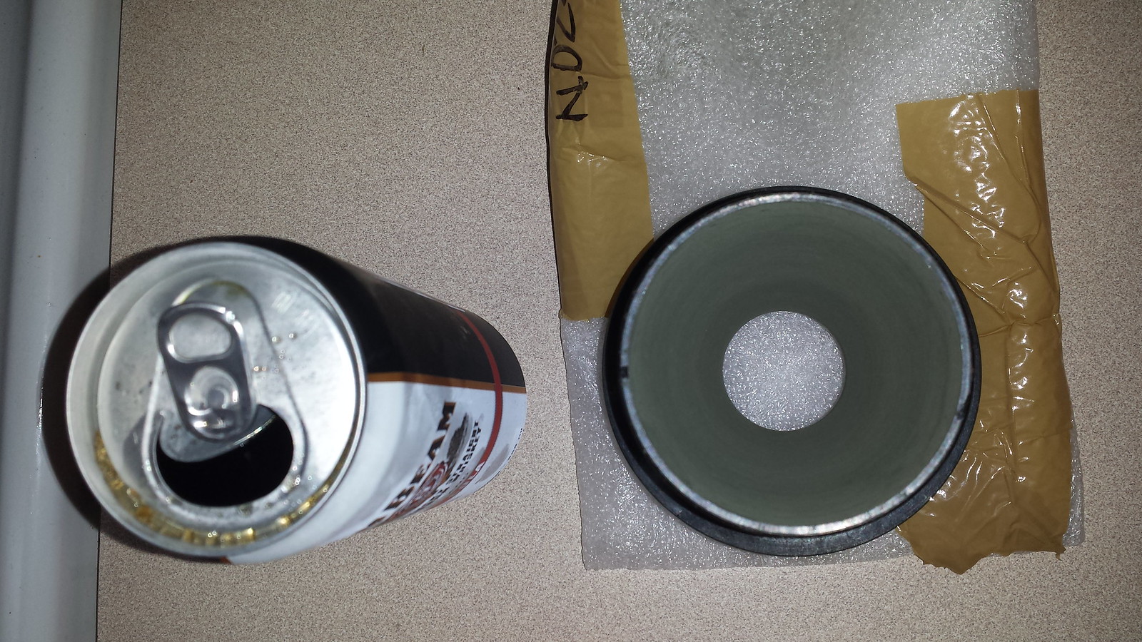
14040065790_6328558ae8_h.jpg

Nozzle v. whiskey & coke in a can. They are both good.


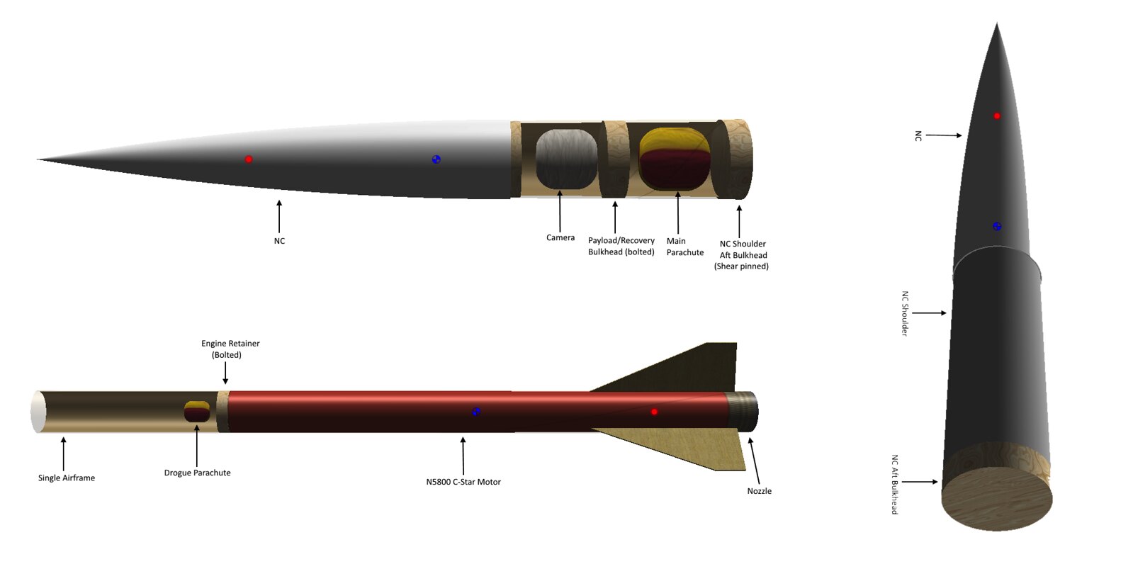
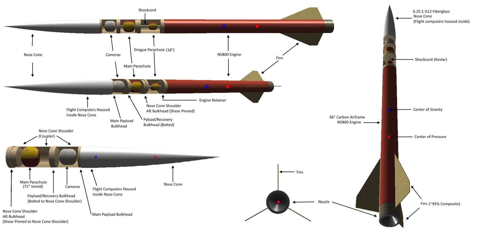
I put together some more quick CADs of the recovery, so hopefully this helps others understand a little bit better. I think one of the most important parts of this recovery is that the deployment of the drogue does not accidentally deploy the main. Once I get to the recovery portion of this vehicle, I will calculate in more detail to determine what is needed. You can read all the research papers you want, but there is no certainty that you completely understand what you read and that it will work in your application and/or building technique. It is however the best place to start, especially for a project like this. Because of my understanding of this I always perform ground testing and will do so thoroughly for this vehicles recovery section.

14259565233_37f131884f_h.jpg

A quick description on the drawings. The NC couples directly into the single airframe. The electronics are housed inside the NC and the cameras are below the flight electronics. There will be a hole to allow ambient pressure sampling ~2-2.5" down from the ELC/CAM bulkhead.

The main is housed in between the Payload/Recovery bulkhead and the NC shoulder (coupler), aft bulkhead. That aft bulkhead is shear-pinned into the the NC shoulder (coupler). It is ejected via pyro charges that are housed on top of the Payload/Recovery bulkhead (middle bulkhead).

All of this is contained inside the NC coupler and then inserted into the single airframe. The drogue rest above the motor casing and is deployed via pyro charges that are housed on top of the NC shoulder (coupler), aft bulkhead. Everything is harnessed together.

14241265335_57acce4124_h.jpg

Went ahead and put one together with just a little bit more detail.

Will take and post pictures of the casing tomorrow.


Mat
 
You said you have thick walled carbon tube. Is the nosecone thicker too in order to match diameters?
 
You said you have thick walled carbon tube. Is the nosecone thicker too in order to match diameters?

Yes the airframe in reality is ~3.18mm thick and so is the nose cone. They do both have the same OD and it is a smooth transition. The nose cone shoulder (coupler) tube is even ~3.18mm thick but obviously it has a different OD (just in case it needed to be said :p).

In case you noticed, a couple of the drawings (first picture) at certain angles, makes the nose cone appear as if it has a slightly smaller OD.
 
Last edited:
As promised pictures of the casing.

14254033155_5eb2315e94_c.jpg

Motor casing next to a old retired DX3.

14253674474_16be58a8c6_c.jpg

Layout of how everything will fit inside.

14067424160_a60ab245a1_c.jpg

Test fitted with some mock fins. Fin on the right are one of the first versions designed and are for a three fin vehicle. Fin on the left is one of the more current designs and are for a four fin vehicle.
 
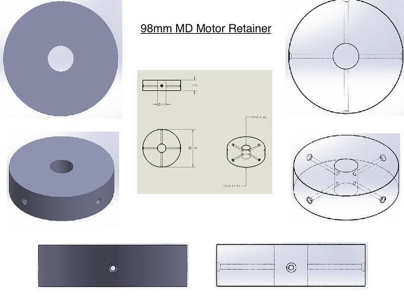
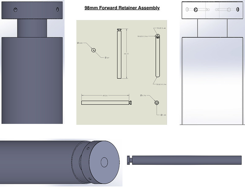
I had some time to do some quick drawings of the forward motor retainer. Its job is to hold the motor in place and prevent it from falling out the bottom. It is designed to be screwed into the airframe and an eyebolt/washer combo on top will hold it from falling out the bottom. (I forgot to add the eyebolt/washer in the drawing.) This also adds some more forward weight to help balance the added weight from the in brackets, caps, big reinforced fillets, etc.

Edit: The diameter of the screw holes is not the actual size and order.

This retainer will also be used in 2 stage configurations (such is being deployed next month in a 2-stage attempt) in the sustainer. Also not shown in the drawings is that it has a groove to allow taper wire to run past to ignite the sustainer motor. This has been my biggest contributing factor in making this part. I have used the Aeropack MD retainers before but I wanted something different and more capable of equal MD staging.

14352000231_fe670d8780_c.jpg


14354453284_72d8e885d1_c.jpg


The next drawings to come is the fin brackets and caps. I am hoping to start making these parts within 2 weeks from now.

Mat
 
Last edited:
Lol. I should also take a photograph of the current 3 fin design so it is a fair comparison. Nonetheless, it is 3.4".

Adding an observation made over the years. The faster you go, the farther out from the airframe you have to go to get in clean air; in my humble opinion, it is important to get fin area outside of the "shock cone". The cone is speed dependent and airframe length does play a part; ie: the shorter the rocket and the faster it moves, the higher the potential for the fins to be blanked out by the cone. I have seen lots of size "optimized" finned rockets wiggle, wobble, tumble, and shred when they really get moving. Several fairly experienced flyers have moved to fins that span at least 1X the diameter of the airframe. 1.3-1.5 times the diameter is the sweet spot I've settled into. I do understand the desire to have short span, long root designs, as it often helps reduce flex in the fins; it is undeniably true that its easier to keep shorter spanned fins in place than longer spanned fins, but I like my rockets to fly straight:). Your mileage may vary.

-Eric-

https://www.everyspec.com/MIL-HDBK/...oad.php?spec=MIL-HDBK-762_NOTICE-2.018535.PDF
 

For those that don't have the time right now to download, read, and digest the referenced document; care to simply state what you're seeking to prove/disprove with that document? I don't work for the military nor work in the aerospace industry; though I understand there is much to be learned from their findings, model rocketry is a merely a hobby that I'm most often involved with. I've been doing rocketry to various degrees for the majority of my life and see myself as a decent rocket hobbyist: nothing more nothing less. I'm simply sharing my observations and experiences; what are you seeking to share?

Thank you.

-Eric-

I'm assuming that butalane is referencing that document because it is relevant. The closer we get to military performance levels, the research has already been done for us. Just scaling up model rocket fins and hoping for the best might not be prudent. All of these popular long root/clipped delta fins are not the best when it comes to stability at multiple mach speeds. Which just reinforces the rules of thumb that you already mentioned about shock cone/fin blanking.
 
release of the version 2 Max Q Aerospace fin cans with new options. Coming soon....A couple military designs with four fins and options for canted fins for spin stabilization.

Can't wait to see these!

Also, great thread Mat. Thank you for your detailed posts and thought processes and being open to challenges from the community. It's the way we all learn and it has been a great read. Look forward to seeing the build progress!

Phil
 
Last edited:
That paper says that an underexpanded exhaust plume reduces stability. That contradicts everything I have read which says that rockets are more stable under boost...
 
That paper says that an underexpanded exhaust plume reduces stability. That contradicts everything I have read which says that rockets are more stable under boost...

This I don't understand. Of all the rockets I have seen go unstable, every one of them were under boost. The squirrelly ones became stable once the motor stopped motoring.
 
This I don't understand. Of all the rockets I have seen go unstable, every one of them were under boost. The squirrelly ones became stable once the motor stopped motoring.

Other factors come into play such as cg shift.

I was talking about effects like the flow of gases down the core stabilizing the rocket and things like that.
 
Only the first page came through for me. The original is 716 pages and well worth the download. I have been researching this very paper in advance of the release of the version 2 Max Q Aerospace fin cans with new options. Coming soon....A couple military designs with four fins and options for canted fins for spin stabilization.

Cooooooool!

I'm assuming that butalane is referencing that document because it is relevant. The closer we get to military performance levels, the research has already been done for us. Just scaling up model rocket fins and hoping for the best might not be prudent. All of these popular long root/clipped delta fins are not the best when it comes to stability at multiple mach speeds. Which just reinforces the rules of thumb that you already mentioned about shock cone/fin blanking.

That's all. I was simply pointing to a resource that had data and guidelines relevant to the discussion. I wasn't trying to prove, disprove or argue anything, just point to a resource that could be looked at if someone wanted a wealth of information on an already study subject.

That paper says that an underexpanded exhaust plume reduces stability. That contradicts everything I have read which says that rockets are more stable under boost...

As gas flow expands in the exit cone, there is a pressure force acting on the surface (from which additional thrust is derive). This is why relatively larger exit cones (in lower ambient pressure environments) perform better. In most cases this gas passes across a uniform exit plan and applies a uniform force but in the case of underexpansion this plan is not defined by the exit plane of the nozzle and is not necessarily uniform (due to flow attaching, turbulent effects, etc). If it is not uniform, large differences in force can develop across the nozzle surface which manifest in an overall lateral force on the exit cone. Scarfed nozzles also have a nonlinear dimension of thrust due to a nonuniform exit cone. J2X had problems with this when it was being tested ... Ill see if I can find the papers.
 
in the case of underexpansion this plan is not defined by the exit plane of the nozzle and is not necessarily uniform (due to flow attaching, turbulent effects, etc). If it is not uniform, large differences in force can develop across the nozzle surface which manifest in an overall lateral force on the exit cone.
And base drag too. Don't forget about base drag!
 
I was going to mention base drag. It also seems possible that at subsonic speeds, the expanding plume pushes a bow wave of air that disturbs airflow over the fins if the fins are swept back past the end of the rocket, maybe? There's also things like combustion instabilities.
 
This I don't understand. Of all the rockets I have seen go unstable, every one of them were under boost. The squirrelly ones became stable once the motor stopped motoring.
Base drag increases stability. That's why short, fat rocket are more stable than simple Cg-Cp relationships will predict. The base drag of a rocket under propulsion is quite low but as soon a the thrust cuts off, the base drag increases dramatically so that a rocket that is marginally stable, or even unstable, under thrust will often stabilize after motor burnout.

Check out Figure 5-156 on page 5-225 in HDBK-762 to see the plume-on/plume-off effect versus Mach Number. The faster you go the larger the effect.

Bob
 
Back
Top