Smartphone GPS Tracker Version 1.0

The Rocketry Forum

Help Support The Rocketry Forum:

This site may earn a commission from merchant affiliate links, including eBay, Amazon, and others.

Derek

Well-Known Member
Joined
Aug 30, 2012
Messages
1,405
Reaction score
2
Note:

This project has evolved into my Rocket Track GPS tracker. See here:

https://www.rocketryforum.com/showt...S-Tracker-for-Smartphones&p=522569#post522569

I've been working on a GPS tracker that uses a smartphone as the display. The system consists of three components:

1. GPS transmitter
2. Receiver with Bluetooth interface
3. Android smartphone with the correct apps

The idea is to use a simple, inexpensive, unlicensed radio link between the rocket and a base station. The GPS receiver in the rocket sends the current position over the radio link to the base station, which in turn relays the data to a smartphone for display. The simplist, most universal interface for external devices available on smartphones is Bluetooth. Therefore base station actually consists of two transceivers, one for the air link to the rocket and a Bluetooth slave that connects to the smartphone. By disabling the GPS in the phone and using the GPS data from the rocket, apps like Google maps display the rocket's position on the map, not the smartphone's!

Only Android is supported because that is what I use. I'm not familiar enough (nor care enough) to see if there are apps for iOS devices that would work with this setup.

System Components

GPS transmitter:

tracker_small.jpg

Base station receiver with Bluetooth interface:

bt_rx_small.jpg

Motivation:

I don't really need a tracker where I fly, but I like gadgets and a GPS tracker definitely qualifies as a neat gadget. However I have no desire to get a ham license and the $400+ radio and equiptment to use a licensed tracker, especially since I already own a vastly more capable device. The goal is to make this small, simple and most importantly, cheap!

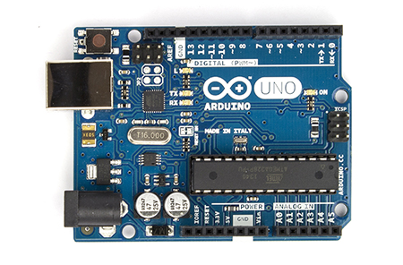
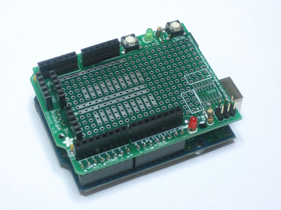
Version 1.0 of the transmitter has less than $80 in parts. The receiver is even less at about $40 because I already had the Arduino ($25), Bluetooth shield ($20) and prototype shield ($10). Note these prices are approximate and don't include shipping.

The system is based on the 3DR Radio developed by the DIY Drones people. In the US, It operates on the unlicensed 915 MHz ISM band. The maximum output power of the transceiver is 100 mW.

Version 1.0 is primarily a proof of concept and for component evaluation testing. I'm trying to keep the amount of software written to an absolute minimum. The app used on the smartphone is the standard Google maps app. If you want to log the rocket's track, you can use Google's My Tracks app instead. I haven't written a single line of Android code. The Arduino isn't needed, but it provides a nice modular base with a power supply for the radio and BT shield.

Questions:

1. Does it work?

Yes. Testing I have done around my house and at a nearby field shows it works really well given the investment in money and time. At this point I have not mounted it in a rocket simply because my club hasn't had a launch yet. Mid January will be the first real test.

2. What is the range?

I don't know this answer, yet. The radio manufacturer states that the range is apporximately 1 mile, and it may very well be under certain conditions. I haven't done enough testing to answer this completely. I have tested it over several hundred yards and it has worked just fine.

3. Does it work with my iPhone?

No. See above.

4. Do I need cell coverage at the field?

No. This tracker will work with phones or tablets without cellular coverage or plans. However, if you want to actually see where your rocket is on a map, you need to save an offline version of the map beforehand.

5. Are the any restrictions on its use?

In the US, not that I'm aware of. The radio operates in the unlicensed 915 MHz ISM band and is under the power limits for this band. It does not use cell phones or the cellular network to transmit the position.

6. Are you going to make it better?

Yep, that is the plan. Version 2.0 is hoped to have an altimeter and accelerometer in the rocket, and hopefully a simpler receiver.

7. Are you going to sell the tracker?

No.

8. Are you going to release the plans?

Yes! I plan on releasing everything you need to reproduce this tracker for yourself. Version 1.0 can be built in under an hour.

9. The Bluetooth base station seems like a stupid hack. Why not just use Bluetooth (or Wifi) in the rocket?

Bluetooth doesn't have the range that these radios have, and Wifi requires more complex electronics in the rocket. Additionally, Android already has the ability to use an external Bluetooth GPS so all the existing map apps will just work.

Each of the components are detailed in following posts.

Enjoy!

Derek

Update 1 (12-30-12): Removed Arduino code statement and updated prices.
Update 2 (12-30-12): Added system overview and question 9.
Update 3 (4-24-13): Added link to Rocket Track thread
 
Last edited:
The actual GPS tracker that gets mounted in the rocket consists of three components:

1. GPS receiver module with integrated antenna
2. Radio module with external antenna
3. Battery

The final configuration of these components looks like this:

tracker_small.jpg

The dimensions of the tracker are 0.90" wide x 2.37" long x 0.45" thick, exclusive of the battery and antenna. With a small enough battery, it will fit in a BT-50 body tube with a little bit of room to spare. It can be made a little bit smaller, but I purposely left a small margin of perf board around the components to work as a bumper to protect the components.

Initially I built the tracker with the GPS module at a right angle to the board in hopes of improving satellite reception while the rocket is straight up and down, but it required a little cable to the radio and I was afraid it could be problematic. After studying other GPS trackers on the market, all with the GPS antenna mounted on the same plane as the radio, I rebuilt the tracker the way it is now. This makes the unit more robust and easier to build and mount in the rocket.

Components

1. GPS receiver module

The GPS receiver chosen for version 1.0 is the Fastrax UP501 GPS receiver with a built in antenna:

inhouse_up501_t.jpg


Fastrax has since been acquired by u-blox. All of the documentation can be found here:

https://www.u-blox.com/en/download/documents-a-resources/fastrax-gpsgnss-modules.html

It was chosen because it is small, cheap and readily available. I bought the module from Mouser for $31.35:

https://www.mouser.com/ProductDetail/Fastrax/UP501/?qs=sGAEpiMZZMv/bGM7XKYHK5cWKPdkcWhM

This thing is tiny! It is also extremely sensitive. It will lock on to 5 - 6 satellites and provide a fix in an all metal building. Other very expensive GPSes I've used in the same building with large external antennas can't get a fix. It is amazing.

It is designed to operate on a single cell Lipo battery. Unfortunately this is lower than the radio's voltage requirement. The solution I came up with is to use the 3.3 V voltage regulator on the radio to power the GPS. This eliminates the need for another voltage regulator on the tracker but prevents the use a single cell Lipo to power the tracker.

The antenna is integrated into the module. The picture above is actually of the bottom of the module. The antenna is on the other side (the top) of the module. All you need to do is apply power and it will start outputting NMEA strings. That's it!

2. Radio module

The radio module chosen is the 3DR radio module from DIY Drones:

It is available in a couple of different configurations: 433 MHz or 915 MHz and with or without a built-in USB interface. The module I chose was the 915 MHz "air" module (without USB); cost was $31.99:

BR-3DR915-2T.jpg

https://store.diydrones.com/3DR_Radio_915_Mhz_Air_module_p/br-3dr915.htm

The two radios I considered were this radio and the XBee Pro from Digi. I went with this one because it is smaller (the XBee won't fit in a BT-50 tube), cheaper ($39 for the Digi) and the pins are much easier to work with. At the time I didn't realize that the higher power XBee Pro XSC modules existed. Had I, it may have swayed my decision the other way.

There is a pretty nice Windows program available to configure and test the modules and they are very well documented. Everything you want to know about the radios is here:

BR-3DR433-5T.jpg

https://code.google.com/p/ardupilot-mega/wiki/3DRadio

I changed the configuration of the radios slightly from the factory defaults. You can configure both of the radios at the same time with the GUI. The major change was I lowered the air data rate to "16" (16 kbps) to hopefully improve the range. I'm not sending much data across the link and the default setting was pretty high. The air data rate is covered in the wiki.

The GPS module outputs data at 9600 baud so the radio module's serial speed needs to be set to the "9" setting. The modules support different addresses so multiple pairs can operate at the same time. You can choose any address you like, but both modules have to match. I also enabled the ECC and MAVLink framing options.

The module has a RP-SMA connector for the antenna. The antenna DIY Drones sells is a 2 dBi antenna for $7.95:

WI-W1063-900mhz-2dbi-2T.jpg

https://store.diydrones.com/Antenna_900MHz_RP_SMA_2dBi_p/wi-w1063-900mhz-2dbi.htm

The antenna measures 4.25" in length and can be rotated and bent 90 degrees. I also purchased a longer (~9.25"), higher gain (3.5 dBi) antenna on ebay for $5.80:

https://www.ebay.com/itm/900MHz-3-5dBi-RP-SMA-GSM-Antenna-wireless-router-/290362347165?pt=US_Networking_Boosters_Extenders_Antennas&hash=item439af1ce9d

I plan on trying both antennas on the tracker and measuring the performance of each in the field. The signal plotting utility in the configuration program indicates the bigger antenna is slightly better in the lab. For now I use the smaller antenna on the tracker and the larger one on the base station.

3. Battery

The GPS module is designed to operate from a voltage of 3.0 V to 4.2 V, which is the safe operating range of a single cell Lipo. The radio has an on-board voltage regulator that operates from ~4.5 V to over 12 V (I looked it up, but forget the exact range). Unfortunately, they don't overlap. In theory you could run the tracker off a one cell Lipo as the actual radio module will operate down to 2.5 V, but in that case the LDO is technically operating out of spec. It will probably work just fine, especially if the Lipo is fully charged, but I chose a safer option, a standard 9 V battery. It also helped that I happened to have a few spare 9 V battery clips lying around when I started. Future versions may use a Lipo or a 12 V A23 battery.

Construction

Module preperation:

First I started by soldering a single row 0.100" header with the plastic spacer on the bottom (solder on the top) of the GPS module.

Next I soldered another single row 0.100" header to the radio module, but this time I inserted the header though the top and soldered it on the bottom side. This allows you to mount the radio module closer to the perf board.

With the headers installed, it is easier to place the modules on the perf board and experiment with the module placement and cut the perf board to the correct size. The size I cut my perf board to is 2.160" long x 0.900" wide. This allows for a single row of holes between the modules and some space around the perimeter of the modules.

Module pin identification:

Pin 1 of the GPS module is the one closest to the corner in the photo below:

inhouse_up501_t.jpg


The pins on the radio module aren't numbered, but they are clearly labeled on the bottom:

BR-3DR433-3T.jpg


Assembly:

1. I mounted the radio module to the perf board with 3M clear double sided sticky tape. The GPS is held to the board by the soldered connections.

2. Connect the positive (red) lead of the battery connector to the pin labeled 5V on the radio module.

3. Solder a wire to the positive terminal of the large capacitor on the radio module. This is the 3.3 V power for the GPS. See the photo below:

tracker_3v.jpg

4. Connect the 3.3 V power wire to pins 4 and 5 of the GPS module.

5. Solder a 1.0 uF capacitor between the 3.3 V power wire and ground close to the GPS module.

6. Add a wire from the pin labeled TX on the radio module to pin 1 (RX) on the GPS module.

7. Add a wire from the pin labeled RX on the radio module to pin 2 (TX) on the GPS module.

8. Add a wire from the pin labeled GND on the radio module to pin 3 (ground) on the GPS module.

9. Connect the negative (black) lead of the battery connector to the pin labeled GND on the radio module.

That's it! The unused pins can be left unconnected. Double check you connections and check for shorts between the power wires. A picture of my finished tracker is shown below:

tracker_back.jpg

You can now power it up. The radio module has two LEDS for status, a link status LED and a data LED. The green link status LED will flash when the radio doesn't have a link and the red data LED should flash when the GPS outputs data (about once per second).

I covered the transmitter with some clear 1" heat shrink tubing to protect the tracker. It is probably a good idea to wrap it with something to prevent accidental shorts.

Update 1 (12-30-12): Added battery info.
Update 2 (12-31-12): Added assembly instructions.
Update 3 (1-1-13): Added misisng air data rate setting.
 
Last edited:
The tracker communicates with the smartphone through the Bluetooth base station. The version 1.0 base station is built from an Arduino and two Arduino shields, a Bluetooth shield and a prototyping shield that the radio is mounted to. Arduino shields are modular and are assmebled like Legos.

The photo below shows the two shields and the Arduino:

bt_rx_parts.jpg

The assembled base station with the larger antenna looks like this:

bt_rx_small.jpg

Components

1. Arduino

ArduinoUno_R3_Front_450px.jpg


The Arduino is used as a power supply for the base station. I used a Duemilanove, but any one will work just fine. I have the Blink example sketch loaded on mine. The sketch isn't critical, but you need to make sure that any of the pins aren't conflicting with the pins used by the Bluetooth shield.

2. Bluetooth shield

im120417010_3.jpg

https://imall.iteadstudio.com/im120417010.html

I used the Bluetooth Shield version 2.2 from itead Studios. This shield can function as either a Bluetooth master or a slave. For our purposes, only a Bluetooth slave is required. I bought the master / slave version for another project, which is why I had it lying around. The only configuration setting you need to change is the baud rate needs to be set to 9600 to match the radio baud rate. You also need to set the jumpers correctly so that the serial data input is connected to the correct pin. If you follow my assembly instructions, you need to install the RX jumper in the D7 location. The TX jumper isn't needed.

3. Prototyping shield and radio module

protoshield_MED.jpg

https://adafruit.com/products/51

The prototyping shield provides a convenient place to mount the radio module and wire it up to the Bluetooth shield. This shield isn't necessary as the Bluetooth module has prototyping space to mount the radio, but are a couple of resistors that are required and I didn't want to modify the Bluetooth shield. The shield shown above isn't the one I have, but they are all pretty similiar. One thing you want to look for is one with posts so that you can easily wire up the radio module to the shield with jumper wires.

Assembly:

1. Solder the right angle header that is included with the radio module. Insert it from the top and solder it on the bottom.

2. I mounted the radio module to the prototyping shield with some more 3M clear double sided sticky tape.

3. Use a jumper wire to connect the pin labeled GND on the radio module to any of the ground pins on the prototyping shield.

09140-03-L_i_th.jpg

https://www.sparkfun.com/products/9140

4. Use a jumper wire to connect the pin labeled 5V on the radio module to the 5 V pin on the prototyping shield.

5. Use a jumper wire to connect the pin labeled TX on the radio module to pin D7 on the prototyping shield.

That is it for wiring! The data only flows one way (from the rocket to the smartphone), so the other serial data connection isn't needed. If you want to connect it, you need to make a resistor divider (I used 10 K and 20 K ohms) to drop the voltage seen by the radio module from 5 V to under 3.6 V because the inputs on the radio aren't 5 V tolerant.

Assemble the shields and you should be ready to go.

Update 1 (1-1-13): Added assembly instructions
Update 2 (1-14-13): Changed jumper wire to male to female
 
Last edited:
In order to use the built in mapping apps, you need to trick your phone into using an external Bluetooth GPS. This is easily accomplished by disabling the phone's GPS and installing a Bluetooth GPS provider app. To disable the phone's GPS, use the power control widget and turn off the location function (the dot with compass-like icon).

The app I used for the external GPS is a free app called "Bluetooth GPS Provider" by mobile-je.de. You need to pair the Bluetooth shield with the phone before starting this app. You will also need to enable the developer options and enable the mock GPS locations setting. The Bluetooth GPS provider app tells you this when you first launch it.

Here is the startup procedure I use:

1. Power up the tracker.
2. Power up the Bluetooth base station. The link light should be solid green when the link is established.
3. Open the Bluetooth GPS app. Press the big "Start" button.

The key is to have the radio link up and running before you start the Bluetooth GPS app otherwise it fails and you need to kill the app and start over. The GPS doesn't need a fix when you start the app, but the data must be coming into the phone. Once the GPS locks up, you will see the position status in the the Bluetooth GPS app.

Now you can open Google Maps or My Tracks and track your rocket!

I've used this successfully on a Motorola Droid 4 and a Nexus S 4G.

Have fun!

Update 1 (1-25-13): Added developer settings statement
 
Last edited:
Bill of materials for the components

Quantity listed is for each assembly. For the inexpensive items (caps, headers, etc.) I suggest you buy at least 3x the minimum required. I'm not including parts like sticky tape, wires, solder etc.

Transmitter

1. Fastrax UP501 GPS module (qty 1):
https://www.mouser.com/ProductDetail/Fastrax/UP501/?qs=sGAEpiMZZMv%2fbGM7XKYHK5cWKPdkcWhM

2. 3DR Radio module (qty 1):
https://store.diydrones.com/3DR_Radio_915_Mhz_Air_module_p/br-3dr915.htm

3. Antenna for radio module (qty 1):
https://store.diydrones.com/Antenna_900MHz_RP_SMA_2dBi_p/wi-w1063-900mhz-2dbi.htm

4. Perf board (qty 1):
https://www.radioshack.com/product/index.jsp?productId=2103804

5. 0.100" straight headers (qty 2):
https://www.mouser.com/ProductDetail/Molex/22-28-4067/?qs=sGAEpiMZZMv9Q1JI0Mo/tUAmpOKqqXii

6. 1 uF capacitor (qty 1):
https://www.mouser.com/ProductDetail/Kemet/C330C105K5R5TA7301/?qs=sGAEpiMZZMuAYrNc52CMZBLUWqSaUDVJR87ouV9U%2fV0%3d

7. 1" clear heatshrink tubing (at least 2"):
https://www.mouser.com/ProductDetail/3M-Electronic-Specialty/FP301-1-48-Clear-Bulk/?qs=sGAEpiMZZMutDkoVpcgZZqAKB5RBofrpNB4hDjESiu0%3d

Bluetooth base station

1. 3DR Radio module (qty 1):
https://store.diydrones.com/3DR_Radio_915_Mhz_Air_module_p/br-3dr915.htm

2. Antenna for radio module (qty 1):
https://store.diydrones.com/Antenna_900MHz_RP_SMA_2dBi_p/wi-w1063-900mhz-2dbi.htm

3. Prototyping shield (qty 1):
https://www.mouser.com/ProductDetail/Arduino/A000077/?qs=sGAEpiMZZMt0re6d%252b2Rx9qf73YdxzUqK

4. Bluetooth shield (qty 1):
https://imall.iteadstudio.com/im120417010.html

5. Arduino (qty 1):
https://www.mouser.com/ProductDetail/Arduino/A000057/?qs=sGAEpiMZZMuauS8OfZL0hLN0GiQpbEFt

6. Jumper wires (qty 4):
https://www.sparkfun.com/products/9140

Update 1 (1-14-13): Added heatshrink tubing
 
Last edited:
Glad to hear it!

I've done a lot more ground testing since I wrote the first posts. Mostly worst case environment stuff. The range isn't near the claimed 1 mile, but I'm doing the testing around my house where there are lots of leafy trees, houses, cars, etc. Out at the field the range should be much better.

I've also been working on making the tracker more robust and mounting it in my av bay. I've secured the battery leads and I'm waiting for some clear heat shrink tubing to arrive so I can make it less prone to shorts and damage.

Finally, I've started ordering parts for version 2.0 (or maybe 1.5, we'll see). The range testing has convinced me to look at other radios, so I've started ordering parts for the xbee pro modules. I've found a few neat adapter boards for these that should still allow one to easily build the system with minimal electronics skills.

The first real test comes in a little over a week. I can't wait to see how it goes!
 
I've done a lot more ground testing since I wrote the first posts. Mostly worst case environment stuff. The range isn't near the claimed 1 mile, but I'm doing the testing around my house where there are lots of leafy trees, houses, cars, etc. Out at the field the range should be much better.

Well, here's where I need to use it:


So I don't think obstructions will be an issue ;)
 
yeah, not a lot of trees there. :)

I bet the cell service sucks, though.

Nice pics. where is that?
 
That's Black Rock in Northern Nevada.......home to LDRS this year. And yes...there is no cell service.
 
Black Rock's high water table (or something to that effect) eats signal, though...
 
i am new to this forum but have already found may tips. my son and i have only been building rockets for a year but have caught the bug. Derek i am waiting to see results after maiden voyage. we are building our level 1 rocket as i post. i can already see the need for a tracker as we go into the high power arena. you have placed several links in the posts, but would you be able to make a list of all the "small" parts needed to complete this build. i do not have your obvious electronics prowess. but i can build most things if i have the parts. our main launch area is Lucerne Valley in CA, very similar to Black Rock above except we get 4 bars of cell service.

thank you all for sharing your vast amount of knowledge.
 
Welcome to the forum!

I can put together a list of all the items I've bought. That is a good idea. It might take a few days but I'll do it.

Good luck with your level 1 flight. I'm planning on doing my l1 this weekend with the tracker on board.

Derek
 
For those that want to build one for themselves, I'd suggest waiting until I try the Digi modules. I suspect that they will have better range and assembly of the base station should be 100% plug and play. The only soldering needed will be for the transmitter. The downside to the Digi radios is the modules are slightly larger and more expensive.
 
but would you be able to make a list of all the "small" parts needed to complete this build.

I believe I posted all the components necessary to build the system. Please let me know if I missed anything. I really need to draw up a simple schematic for both parts. It would make life easier for those wanting to build one.
 
ok thanks for clarification. i will wait until you try the Digi modules. good luck on your L1 flight. i missed that list of parts must have got too excited thinking about build.
 
well, I just added the consolidated list of parts this morning after I read your suggestion. I don't think you missed anything!
 
For those that want to build one for themselves, I'd suggest waiting until I try the Digi modules.
I've used the Digi 900 Pro XSC modules and they work fine, but you should be able to get better range on the 3DR modules at a low data rate. Have you experimented with that at all? You are supposed to be able to get multiple miles of range at, say, 9600 baud.
 
7. Are you going to sell the tracker?

No.

Why not? Make them at home in your spare time and make a nice profit off of those of us who aren't capable of putting something like this together. It may even be something you can patent.
 
I've used the Digi 900 Pro XSC modules and they work fine, but you should be able to get better range on the 3DR modules at a low data rate. Have you experimented with that at all? You are supposed to be able to get multiple miles of range at, say, 9600 baud.

I have tried lowering the data rate, but there is a minimum rate you can set it to to handle retries (12 kbps iirc). The lowest setting you can therefore use is 16 kbps.

In the air, you may very well get multiple miles of range. on the ground, I haven't seen anything close to that.
 
In the air, you may very well get multiple miles of range. on the ground, I haven't seen anything close to that.
That's pretty typical for the Digi as well. You really can't count on more than a few hundred feet of range on the ground in my experience.
 
Why not? Make them at home in your spare time and make a nice profit off of those of us who aren't capable of putting something like this together. It may even be something you can patent.

Well, I design this stuff for a living, and I have no interest in making more work for myself. I try to do different things outside of work. :)

Having said that, if I were to create a pcb for the transmitter I would be happy to sell it to those who are interested. However it would be up to you to populate the board. You couldn't afford it if I built it. :D

With this goal in mind, I have chosen components that are easily soldered with your average soldering iron. No 0402 or QFN parts if I can help it.

Also there is already a compelling solution for about $300 - $400, so my goal is to build a comparable system at as low a cost as possible. That means some assembly will be required.
 
BTW, what does the Arduino actually do? Seems like you could go from the receiver straight to a Bluetooth serial module (RN-42, say) and skip the Arduino entirely; I've done that with a Digi module and a Nexus 7 tablet.
 
I think it says in his original post that it's being used as the power supply for the receiver shield. It would be trivial to build a suitable 3.3v power supply on a perfboard and eliminate it. They also have a "ground" 3DR module with a USB interface, you could plug that directly into a PC (gasp!) and have the serial driver feed Google Maps. My experience with using wireless connections to replace wires has been that the fewer you have, the better; they just introduce sources of interference with your real-time data stream.

BTW, what does the Arduino actually do? Seems like you could go from the receiver straight to a Bluetooth serial module (RN-42, say) and skip the Arduino entirely; I've done that with a Digi module and a Nexus 7 tablet.
 
BTW, what does the Arduino actually do? Seems like you could go from the receiver straight to a Bluetooth serial module (RN-42, say) and skip the Arduino entirely; I've done that with a Digi module and a Nexus 7 tablet.

Like cerving said, at the moment it is only used as a power supply. The sketch that is loaded on it just blinks a led on and off. I happened to have all the arduino stuff lying around and it makes for a rapid development platform.

However, I do have an actual plan for the arduino. Ultimately I want a solution that provides bearing and range to the rocket as well as logging of altitude and acceleration (and maybe a few other parameters). My path to that solution is to leverage all the incredible work done by the diy drone community and use their ground control station apps for pcs, android and ios devices. The arduino will be needed to format the data correctly for those apps to work.

I've started working on that solution, which I'll plan on calling version 2.0. Ultimately there will probably be a microcontroller in the rocket, but as an intermediate step the base station arduino can do the formatting for the apps and it won't cost anything to implement.
 
You really can't count on more than a few hundred feet of range on the ground in my experience.

Including the newer 250 mw ones? I got about a 1/4 mile range with my radios in a pretty unfavorable environment.

Range for all radio will degrade once the rocket lands. I think the goal is to get as many updates while the rocket is still in the air while coming down under the parachute. as long as you get a something when the rocket is close to the ground I think you can get close enough to pick the signal up again.

we'll see. this is all a fun experiment for me.
 
Like cerving said, at the moment it is only used as a power supply... My path to that solution is to leverage all the incredible work done by the diy drone community and use their ground control station apps for pcs, android and ios devices.
Fair enough. I've taken a slightly different approach; I'm doing all the processing in the tablet using sl4a/python, which makes it pretty easy. But I definitely see the advantage of your approach.
 
My experience with using wireless connections to replace wires has been that the fewer you have, the better....
Sure, but on modern tablets and phones it can be pretty painful to use a wired USB connection and using Bluetooth is programmatically simpler; I haven't had any issues with interference so far; it's all spread-spectrum and on different frequencies.
 
Fair enough. I've taken a slightly different approach; I'm doing all the processing in the tablet using sl4a/python, which makes it pretty easy. But I definitely see the advantage of your approach.

very nice. I wasn't aware of python in android. I'm a hardware guy so I'm trying to minimize the amount of android sw I need to write.
 
Back
Top